OPTO 22 Modular M4RTU User manual

M4RTU/M4IO USER’S GUIDE
Form 0676-100301—March 2010
43044 Business Park Drive • Temecula • CA 92590-3614
Phone: 800-321-OPTO (6786) or 951-695-3000
Fax: 800-832-OPTO (6786) or 951-695-2712
www.opto22.com
Product Support Services
800-TEK-OPTO (835-6786) or 951-695-3080
Fax: 951-695-3017
Email: suppor[email protected]
Web: support.opto22.com

M4RTU/M4IO User’s Guide
ii
M4RTU/M4IO User’s Guide
Form 0676-100301—March 2010
Copyright © 2010 Opto 22.
All rights reserved.
Printed in the United States of America.
The information in this manual has been checked carefully and is believed to be accurate; however, Opto 22 assumes no
responsibility for possible inaccuracies or omissions. Specifications are subject to change without notice.
Opto 22 warrants all of its products to be free from defects in material or workmanship for 30 months from the
manufacturing date code. This warranty is limited to the original cost of the unit only and does not cover installation, labor, or
any other contingent costs. Opto 22 I/O modules and solid-state relays with date codes of 1/96 or later are guaranteed for life.
This lifetime warranty excludes reed relay, SNAP serial communication modules, SNAP PID modules, and modules that
contain mechanical contacts or switches. Opto 22 does not warrant any product, components, or parts not manufactured by
Opto 22; for these items, the warranty from the original manufacturer applies. These products include, but are not limited to,
OptoTerminal-G70, OptoTerminal-G75, and Sony Ericsson GT-48; see the product data sheet for specific warranty
information. Refer to Opto 22 form number 1042 for complete warranty information.
Wired+Wireless controllers and brains and N-TRON wireless access points are licensed under one or more of the following
patents: U.S. Patent No(s). 5282222, RE37802, 6963617; Canadian Patent No. 2064975; European Patent No. 1142245; French
Patent No. 1142245; British Patent No. 1142245; Japanese Patent No. 2002535925A; German Patent No. 60011224.
Opto 22 FactoryFloor, Optomux, and Pamux are registered trademarks of Opto 22. Generation 4, ioControl, ioDisplay,
ioManager, ioProject, ioUtilities, mistic, Nvio, Nvio.net Web Portal, OptoConnect, OptoControl, OptoDataLink, OptoDisplay,
OptoOPCServer, OptoScript, OptoServer, OptoTerminal, OptoUtilities, PAC Control, PAC Display, PAC Manager, PAC Project,
SNAP Ethernet I/O, SNAP I/O, SNAP OEM I/O, SNAP PAC System, SNAP Simple I/O, SNAP Ultimate I/O, and Wired+Wireless
are trademarks of Opto 22.
ActiveX, JScript, Microsoft, MS-DOS, VBScript, Visual Basic, Visual C++, Windows, and Windows Vista are either registered
trademarks or trademarks of Microsoft Corporation in the United States and other countries. Linux is a registered trademark of
Linus Torvalds. Unicenter is a registered trademark of Computer Associates International, Inc. ARCNET is a registered
trademark of Datapoint Corporation. Modbus is a registered trademark of Schneider Electric. Wiegand is a registered
trademark of Sensor Engineering Corporation. Nokia, Nokia M2M Platform, Nokia M2M Gateway Software, and Nokia 31 GSM
Connectivity Terminal are trademarks or registered trademarks of Nokia Corporation. Sony is a trademark of Sony Corporation.
Ericsson is a trademark of Telefonaktiebolaget LM Ericsson. CompactLogix and RSLogix are trademarks of Rockwell
Automation. Allen-Bradley and ControlLogix are a registered trademarks of Rockwell Automation. CIP and EtherNet/IP are
trademarks of ODVA.
All other brand or product names are trademarks or registered trademarks of their respective companies or organizations.

M4RTU/M4IO User’s Guide iii
iii
Table of Contents
Chapter 1: Introduction . . . . . . . . . . . . . . . . . . . . . . . . . . . . . . . . . . . . . . . . . . . . . . . . . . 1
About the M4RTU/M4IO . . . . . . . . . . . . . . . . . . . . . . . . . . . . . . . . . . . . . . . . . . . . . . . . . . . . . . . . . . . . . . . . . . . . . 1
About this Manual . . . . . . . . . . . . . . . . . . . . . . . . . . . . . . . . . . . . . . . . . . . . . . . . . . . . . . . . . . . . . . . . . . . . . . . . . . 1
For Help . . . . . . . . . . . . . . . . . . . . . . . . . . . . . . . . . . . . . . . . . . . . . . . . . . . . . . . . . . . . . . . . . . . . . . . . . . . . . . . . . . . 2
Overview—M4RTU/M4IO Remote Telemetry Unit. . . . . . . . . . . . . . . . . . . . . . . . . . . . . . . . . . . . . . . . . . . . . . 3
Available Options . . . . . . . . . . . . . . . . . . . . . . . . . . . . . . . . . . . . . . . . . . . . . . . . . . . . . . . . . . . . . . . . . . . . . . . 4
Software . . . . . . . . . . . . . . . . . . . . . . . . . . . . . . . . . . . . . . . . . . . . . . . . . . . . . . . . . . . . . . . . . . . . . . . . . . . . . . 5
Possible Applications . . . . . . . . . . . . . . . . . . . . . . . . . . . . . . . . . . . . . . . . . . . . . . . . . . . . . . . . . . . . . . . . . . . . . . . . 6
Basic Architecture. . . . . . . . . . . . . . . . . . . . . . . . . . . . . . . . . . . . . . . . . . . . . . . . . . . . . . . . . . . . . . . . . . . . . . . . . . . 9
Hardware Diagrams . . . . . . . . . . . . . . . . . . . . . . . . . . . . . . . . . . . . . . . . . . . . . . . . . . . . . . . . . . . . . . . . . . . . . . . 10
M4RTU/M4IO Base Unit Overview . . . . . . . . . . . . . . . . . . . . . . . . . . . . . . . . . . . . . . . . . . . . . . . . . . . . . . . 10
Chapter 2: Quick Start . . . . . . . . . . . . . . . . . . . . . . . . . . . . . . . . . . . . . . . . . . . . . . . . . .11
Overview . . . . . . . . . . . . . . . . . . . . . . . . . . . . . . . . . . . . . . . . . . . . . . . . . . . . . . . . . . . . . . . . . . . . . . . . . . . . . . . . 11
Notes for Rev. 2 Controllers . . . . . . . . . . . . . . . . . . . . . . . . . . . . . . . . . . . . . . . . . . . . . . . . . . . . . . . . . . . . . 11
1. Unpacking . . . . . . . . . . . . . . . . . . . . . . . . . . . . . . . . . . . . . . . . . . . . . . . . . . . . . . . . . . . . . . . . . . . . . . . . . . . . 12
2. Installing the Power Supply . . . . . . . . . . . . . . . . . . . . . . . . . . . . . . . . . . . . . . . . . . . . . . . . . . . . . . . . . . . . . . 13
3. Connecting the Battery . . . . . . . . . . . . . . . . . . . . . . . . . . . . . . . . . . . . . . . . . . . . . . . . . . . . . . . . . . . . . . . . . . 14
4. Checking Configuration Jumpers . . . . . . . . . . . . . . . . . . . . . . . . . . . . . . . . . . . . . . . . . . . . . . . . . . . . . . . . . 15
5. Installing Daughter Cards and/or I/O Extender. . . . . . . . . . . . . . . . . . . . . . . . . . . . . . . . . . . . . . . . . . . . . . 15
6. Mounting the M4RTU/M4IO . . . . . . . . . . . . . . . . . . . . . . . . . . . . . . . . . . . . . . . . . . . . . . . . . . . . . . . . . . . . . 16
7. Connecting Power to the M4RTU/M4IO . . . . . . . . . . . . . . . . . . . . . . . . . . . . . . . . . . . . . . . . . . . . . . . . . . . 17
8. Installing I/O Modules . . . . . . . . . . . . . . . . . . . . . . . . . . . . . . . . . . . . . . . . . . . . . . . . . . . . . . . . . . . . . . . . . . . 18
9. Connecting to a Host PC . . . . . . . . . . . . . . . . . . . . . . . . . . . . . . . . . . . . . . . . . . . . . . . . . . . . . . . . . . . . . . . . . 19
Wiring . . . . . . . . . . . . . . . . . . . . . . . . . . . . . . . . . . . . . . . . . . . . . . . . . . . . . . . . . . . . . . . . . . . . . . . . . . . . . . . 19
RS-232 Pin Connections . . . . . . . . . . . . . . . . . . . . . . . . . . . . . . . . . . . . . . . . . . . . . . . . . . . . . . . . . . . 19

M4RTU/M4IO User’s Guide
iv
RS-232 Wiring Scheme . . . . . . . . . . . . . . . . . . . . . . . . . . . . . . . . . . . . . . . . . . . . . . . . . . . . . . . . . . . .19
Configuring Communication . . . . . . . . . . . . . . . . . . . . . . . . . . . . . . . . . . . . . . . . . . . . . . . . . . . . . . . . . . . .20
10. Verifying Communications . . . . . . . . . . . . . . . . . . . . . . . . . . . . . . . . . . . . . . . . . . . . . . . . . . . . . . . . . . . . . . 21
Chapter 3: Installation and Setup . . . . . . . . . . . . . . . . . . . . . . . . . . . . . . . . . . . . . . . 23
Overview. . . . . . . . . . . . . . . . . . . . . . . . . . . . . . . . . . . . . . . . . . . . . . . . . . . . . . . . . . . . . . . . . . . . . . . . . . . . . . . . . 23
Setting Configuration Jumpers and Switches . . . . . . . . . . . . . . . . . . . . . . . . . . . . . . . . . . . . . . . . . . . . . . . . . 24
I/O Board Jumpers . . . . . . . . . . . . . . . . . . . . . . . . . . . . . . . . . . . . . . . . . . . . . . . . . . . . . . . . . . . . . . . . . . . . .24
EEPROM/RAM Jumper (E/R) . . . . . . . . . . . . . . . . . . . . . . . . . . . . . . . . . . . . . . . . . . . . . . . . . . . . . . . .26
Autoboot Jumper (AUTO) . . . . . . . . . . . . . . . . . . . . . . . . . . . . . . . . . . . . . . . . . . . . . . . . . . . . . . . . . .26
Communication Mode Jumper (X0) . . . . . . . . . . . . . . . . . . . . . . . . . . . . . . . . . . . . . . . . . . . . . . . . .26
Boot Loader Jumper (X1) . . . . . . . . . . . . . . . . . . . . . . . . . . . . . . . . . . . . . . . . . . . . . . . . . . . . . . . . . . .26
Host Port Jumpers (H0, H1) . . . . . . . . . . . . . . . . . . . . . . . . . . . . . . . . . . . . . . . . . . . . . . . . . . . . . . . . .26
Baud Rate Jumpers (BAUD 0–3) . . . . . . . . . . . . . . . . . . . . . . . . . . . . . . . . . . . . . . . . . . . . . . . . . . . . .26
Address Jumpers (ADDRESS 0–7) . . . . . . . . . . . . . . . . . . . . . . . . . . . . . . . . . . . . . . . . . . . . . . . . . . .27
Ring Indicator Jumper (JP1 ) . . . . . . . . . . . . . . . . . . . . . . . . . . . . . . . . . . . . . . . . . . . . . . . . . . . . . . . . . . . .27
Processor Board Jumpers for Rev. 1 Units . . . . . . . . . . . . . . . . . . . . . . . . . . . . . . . . . . . . . . . . . . . . . . . . .28
Flash Jumpers (FL) . . . . . . . . . . . . . . . . . . . . . . . . . . . . . . . . . . . . . . . . . . . . . . . . . . . . . . . . . . . . . . . . .29
*RAM Jumper (MJ) . . . . . . . . . . . . . . . . . . . . . . . . . . . . . . . . . . . . . . . . . . . . . . . . . . . . . . . . . . . . . . . .29
ROM Jumper (RJ) . . . . . . . . . . . . . . . . . . . . . . . . . . . . . . . . . . . . . . . . . . . . . . . . . . . . . . . . . . . . . . . . . .29
Ring Indicator Jumper (JP2 ) . . . . . . . . . . . . . . . . . . . . . . . . . . . . . . . . . . . . . . . . . . . . . . . . . . . . . . . .29
Serial Port Switches (COM1) . . . . . . . . . . . . . . . . . . . . . . . . . . . . . . . . . . . . . . . . . . . . . . . . . . . . . . . . . . . . .30
TERM IN/TERM OUT . . . . . . . . . . . . . . . . . . . . . . . . . . . . . . . . . . . . . . . . . . . . . . . . . . . . . . . . . . . . . . .30
2-WIRE/4-WIRE . . . . . . . . . . . . . . . . . . . . . . . . . . . . . . . . . . . . . . . . . . . . . . . . . . . . . . . . . . . . . . . . . . .30
Connecting Field Wiring. . . . . . . . . . . . . . . . . . . . . . . . . . . . . . . . . . . . . . . . . . . . . . . . . . . . . . . . . . . . . . . . . . . . 30
Digital Modules . . . . . . . . . . . . . . . . . . . . . . . . . . . . . . . . . . . . . . . . . . . . . . . . . . . . . . . . . . . . . . . . . . . . . . . .31
Analog Modules . . . . . . . . . . . . . . . . . . . . . . . . . . . . . . . . . . . . . . . . . . . . . . . . . . . . . . . . . . . . . . . . . . . . . . .32
Connecting to a Host PC or Modem. . . . . . . . . . . . . . . . . . . . . . . . . . . . . . . . . . . . . . . . . . . . . . . . . . . . . . . . . . 32
RS-232 COM0 Pin Connections . . . . . . . . . . . . . . . . . . . . . . . . . . . . . . . . . . . . . . . . . . . . . . . . . . . . . . . . . .33
RS-485 COM1 Pin Connections . . . . . . . . . . . . . . . . . . . . . . . . . . . . . . . . . . . . . . . . . . . . . . . . . . . . . . . . . .33
Wiring to a Host PC . . . . . . . . . . . . . . . . . . . . . . . . . . . . . . . . . . . . . . . . . . . . . . . . . . . . . . . . . . . . . . . . . . . .33
RS-232 COM0 . . . . . . . . . . . . . . . . . . . . . . . . . . . . . . . . . . . . . . . . . . . . . . . . . . . . . . . . . . . . . . . . . . . . .34
RS-485 COM1 . . . . . . . . . . . . . . . . . . . . . . . . . . . . . . . . . . . . . . . . . . . . . . . . . . . . . . . . . . . . . . . . . . . . .34
Wiring to a Modem (a DCE device) . . . . . . . . . . . . . . . . . . . . . . . . . . . . . . . . . . . . . . . . . . . . . . . . . . . . . . .35
Computer (DTE) RS-232 COM Port Pin Assignments . . . . . . . . . . . . . . . . . . . . . . . . . . . . . . . . . . .36
Connecting to Opto 22 I/O Units . . . . . . . . . . . . . . . . . . . . . . . . . . . . . . . . . . . . . . . . . . . . . . . . . . . . . . . . . . . . 37
LED Indicators . . . . . . . . . . . . . . . . . . . . . . . . . . . . . . . . . . . . . . . . . . . . . . . . . . . . . . . . . . . . . . . . . . . . . . . . . . . . 39

M4RTU/M4IO User’s Guide v
v
Chapter 4: Software and Firmware . . . . . . . . . . . . . . . . . . . . . . . . . . . . . . . . . . . . . .41
Overview . . . . . . . . . . . . . . . . . . . . . . . . . . . . . . . . . . . . . . . . . . . . . . . . . . . . . . . . . . . . . . . . . . . . . . . . . . . . . . . . 41
OptoControl. . . . . . . . . . . . . . . . . . . . . . . . . . . . . . . . . . . . . . . . . . . . . . . . . . . . . . . . . . . . . . . . . . . . . . . . . . . . . . 41
Configuring Communications to the M4RTU/M4IO . . . . . . . . . . . . . . . . . . . . . . . . . . . . . . . . . . . . . . . . 41
Configuring the M4RTU/M4IO and M4RTUX . . . . . . . . . . . . . . . . . . . . . . . . . . . . . . . . . . . . . . . . . . . . . . 42
Configuring M4RTU/M4IO and M4RTUX I/O Units . . . . . . . . . . . . . . . . . . . . . . . . . . . . . . . . . . . . . . . . . 42
Configuring Additional I/O Units . . . . . . . . . . . . . . . . . . . . . . . . . . . . . . . . . . . . . . . . . . . . . . . . . . . . . . . . 42
Configuring the I/O Points . . . . . . . . . . . . . . . . . . . . . . . . . . . . . . . . . . . . . . . . . . . . . . . . . . . . . . . . . . . . . . 43
Storing User Strategies into M4RTU/M4IO Flash EEPROM . . . . . . . . . . . . . . . . . . . . . . . . . . . . . . . . . . . 43
OptoDisplay and OptoServer . . . . . . . . . . . . . . . . . . . . . . . . . . . . . . . . . . . . . . . . . . . . . . . . . . . . . . . . . . . . . . . 43
Updating the M4RTU/M4IO Firmware . . . . . . . . . . . . . . . . . . . . . . . . . . . . . . . . . . . . . . . . . . . . . . . . . . . . . . . 44
Chapter 5: Field Wiring . . . . . . . . . . . . . . . . . . . . . . . . . . . . . . . . . . . . . . . . . . . . . . . . .45
Overview . . . . . . . . . . . . . . . . . . . . . . . . . . . . . . . . . . . . . . . . . . . . . . . . . . . . . . . . . . . . . . . . . . . . . . . . . . . . . . . . 45
Field Wiring Terminals. . . . . . . . . . . . . . . . . . . . . . . . . . . . . . . . . . . . . . . . . . . . . . . . . . . . . . . . . . . . . . . . . . . . . 47
Connecting Field Wiring . . . . . . . . . . . . . . . . . . . . . . . . . . . . . . . . . . . . . . . . . . . . . . . . . . . . . . . . . . . . . . . . . . . 48
Wiring Digital Modules . . . . . . . . . . . . . . . . . . . . . . . . . . . . . . . . . . . . . . . . . . . . . . . . . . . . . . . . . . . . . . . . . . . . 49
Most Input and Output Modules . . . . . . . . . . . . . . . . . . . . . . . . . . . . . . . . . . . . . . . . . . . . . . . . . . . . . . . . 49
Quadrature Input Module . . . . . . . . . . . . . . . . . . . . . . . . . . . . . . . . . . . . . . . . . . . . . . . . . . . . . . . . . . . . . . 50
Wiring Analog Modules. . . . . . . . . . . . . . . . . . . . . . . . . . . . . . . . . . . . . . . . . . . . . . . . . . . . . . . . . . . . . . . . . . . . 50
Voltage Input and Output Modules . . . . . . . . . . . . . . . . . . . . . . . . . . . . . . . . . . . . . . . . . . . . . . . . . . . . . . 50
Milliamp Current Input and Output Modules . . . . . . . . . . . . . . . . . . . . . . . . . . . . . . . . . . . . . . . . . . . . . . 51
0 to 5 Amp AC/DC Current Input or Velocity Input . . . . . . . . . . . . . . . . . . . . . . . . . . . . . . . . . . . . . . . . . 52
Thermocouple Input or ICTD Temperature Input Module . . . . . . . . . . . . . . . . . . . . . . . . . . . . . . . . . . . 53
100-Ohm RTD Input Module . . . . . . . . . . . . . . . . . . . . . . . . . . . . . . . . . . . . . . . . . . . . . . . . . . . . . . . . . . . . 54
Rate Module . . . . . . . . . . . . . . . . . . . . . . . . . . . . . . . . . . . . . . . . . . . . . . . . . . . . . . . . . . . . . . . . . . . . . . . . . . 54
Time Proportional Output Module . . . . . . . . . . . . . . . . . . . . . . . . . . . . . . . . . . . . . . . . . . . . . . . . . . . . . . . 55
Appendix A: Troubleshooting . . . . . . . . . . . . . . . . . . . . . . . . . . . . . . . . . . . . . . . . . .57
M4RTU/M4IO Troubleshooting Chart. . . . . . . . . . . . . . . . . . . . . . . . . . . . . . . . . . . . . . . . . . . . . . . . . . . . . . . . 57
Appendix B: Cable and Connector Specifications . . . . . . . . . . . . . . . . . . . . . . . .59
Serial Communication Cables. . . . . . . . . . . . . . . . . . . . . . . . . . . . . . . . . . . . . . . . . . . . . . . . . . . . . . . . . . . . . . . 59

M4RTU/M4IO User’s Guide
vi
M4RTU/M4IO Connectors . . . . . . . . . . . . . . . . . . . . . . . . . . . . . . . . . . . . . . . . . . . . . . . . . . . . . . . . . . . . . . . . . . 60
Appendix C: Product Specifications . . . . . . . . . . . . . . . . . . . . . . . . . . . . . . . . . . . . 61
M4RTU/M4IO Base Unit Hardware Specifications. . . . . . . . . . . . . . . . . . . . . . . . . . . . . . . . . . . . . . . . . . . . . . 61
. . . . . . . . . . . . . . . . . . . . . . . . . . . . . . . . . . . . . . . . . . . . . . . . . . . . . . . . . . . . . . . . . . . . . . . . . . . . . . . . . . . . . . . . . 62
Appendix D: Worksheets . . . . . . . . . . . . . . . . . . . . . . . . . . . . . . . . . . . . . . . . . . . . . . 63
I/O Module Worksheets . . . . . . . . . . . . . . . . . . . . . . . . . . . . . . . . . . . . . . . . . . . . . . . . . . . . . . . . . . . . . . . . . . . . 63
M4RTU/M4IO Base Unit—I/O Module Worksheet . . . . . . . . . . . . . . . . . . . . . . . . . . . . . . . . . . . . . . . . .64
M4RTUX I/O Extender—I/O Module Worksheet . . . . . . . . . . . . . . . . . . . . . . . . . . . . . . . . . . . . . . . . . . .65
Field Wiring Worksheets . . . . . . . . . . . . . . . . . . . . . . . . . . . . . . . . . . . . . . . . . . . . . . . . . . . . . . . . . . . . . . . . . . . 66
Field Wiring Worksheet 1 . . . . . . . . . . . . . . . . . . . . . . . . . . . . . . . . . . . . . . . . . . . . . . . . . . . . . . . . . . . . . . .66
Field Wiring Worksheet 2 . . . . . . . . . . . . . . . . . . . . . . . . . . . . . . . . . . . . . . . . . . . . . . . . . . . . . . . . . . . . . . .67
M4RTU/M4IO Power Consumption Worksheet Instructions. . . . . . . . . . . . . . . . . . . . . . . . . . . . . . . . . . . . . 68
Power Consumption Worksheet . . . . . . . . . . . . . . . . . . . . . . . . . . . . . . . . . . . . . . . . . . . . . . . . . . . . . . . . .69
Index . . . . . . . . . . . . . . . . . . . . . . . . . . . . . . . . . . . . . . . . . . . . . . . . . . . . . . . . . . . . . . . . . 71

M4RTU/M4IO User’s Guide 1
1
1: Chapter 1
Introduction
About the M4RTU/M4IO
Thank you for purchasing an Opto 22 Modular M4RTU or M4 I/O Controller. The M4RTU/M4IO
delivers the functionality and robustness of a remote telemetry unit with the power of a distributed
automation system, all in one controller.
The M4RTU/M4IO consolidates two processors on a single processor board. Program control and
host communications are handled by a 32-bit microprocessor, while another processor handles I/O
interfacing and control. This dual-processor board is combined with a digital/analog I/O board, a
3-slot vertical expansion bus board (M4BUS), and a modular power supply into a compact
aluminum extrusion package that can be mounted horizontally or vertically.
A complete line of modular adapter cards is also available, providing a wide range of communication
options.
About this Manual
This reference manual provides complete specifications and instructions to set up and install a
M4RTU or M4 I/O controller. In this manual you’ll find:
Chapter 1, “Introduction”—Product support information as well as general information about
the M4RTU/M4IO, its applications, basic architecture, and hardware diagrams.
Chapter 2, “Quick Start”—A brief explanation of how to quickly get the M4RTU/M4IO up and
running.
Chapter 3, “Installation and Setup”—Detailed descriptions of jumper settings and
communication connections.
Chapter 4, “Software and Firmware”—General software and firmware overviews and
communication procedures.
Chapter 5, “Field Wiring”—Detailed information on digital and analog field wiring, including
examples.
Chapter A, “Troubleshooting”—Tips for resolving problems you may encounter.

FOR HELP
M4RTU/M4IO User’s Guide
2
Chapter B, “Cable and Connector Specifications”—A list of recommended communication
cables and connectors.
Chapter C, “Product Specifications”—A list of specifications for the M4RTU/M4IO.
Chapter D, “Worksheets”—Worksheets that can be used to plan field wiring installation and
power consumption.
For Help
If you have problems installing or using the M4RTU or M4 I/O and cannot find the help you need in
this guide or on our website, contact Opto 22 Product Support.
Phone: 800-TEK-OPTO (835-6786)
951-695-3080
(Hours are Monday through Friday,
7 a.m. to 5 p.m. Pacific Time)
Fax: 951-695-3017
Email: suppor[email protected]
Opto 22 website: www.opto22.com
When calling for technical support, be prepared to provide the following information about your
system to the Product Support engineer:
•Software and version being used
•Controller firmware (kernel) version
•PC configuration
•A complete description of your hardware and operating systems, including:
– jumper configuration
– accessories installed (such as expansion daughter cards)
– type of power supply
– types of I/O units installed
– third-party devices installed (e.g., barcode readers)
•Specific error messages seen
NOTE: Email messages and
phone calls to Opto 22
Product Support are
grouped together and
answered in the order
received.

CHAPTER 1: INTRODUCTION
M4RTU/M4IO User’s Guide 3
3
Overview—M4RTU/M4IO Remote Telemetry Unit
The M4RTU/M4IO combines the features and functions of a Remote Telemetry Unit (RTU) with the
power of a distributed automation system all in a single controller. The M4RTU/M4IO is built to be
deployed in any type of network or remote control environment. The M4RTU/M4IO was designed
specifically for industrial field applications, such as wastewater treatment, well monitoring, tank
farms, substation automation, and gas/petrochemical applications.
The M4RTU/M4IO is fully supported with FactoryFloor, Opto 22’s legacy suite of Windows™ software
for industrial automation customers. FactoryFloor consists of four integrated components:
•OptoControl™, a graphical, flowchart-based development environment for control solutions
•OptoDisplay™, a graphical, multimedia operator interface package
•OptoServer™, a data server that connects the controller network with the PC-based
FactoryFloor network
•Plus OptoConnect™, a drag-and-drop database utility
The M4RTU/M4IO is part of Opto 22’s Modular line of controllers. These units feature a modular
design that incorporates Opto 22’s M4 bus technology (M4BUS). This technology lets customers
tailor their controller and interface hardware to the scale of the project at hand. The M4BUS allows
users to create custom interface configurations by simply plugging in one or more of the modular
interface cards. These open options allow customers to share real-time plant floor data with
telemetry or network-based control and information systems. All modular interface cards for serial
communications or network connectivity are supported as standard selections in the FactoryFloor
software.
The M4RTU/M4IO consolidates two processors on a single processor board. Program control and
host communications are handled by a 32-bit 68020 microprocessor, while a 16-bit 80C196
processor handles I/O interfacing and control. This dual-processor board is combined with a
digital/analog I/O board, a 3-slot vertical expansion bus board (M4BUS), and a modular power
supply into a compact aluminum extrusion package that can be mounted horizontally or vertically.

OVERVIEW—M4RTU/M4IO REMOTE TELEMETRY UNIT
M4RTU/M4IO User’s Guide
4
The M4RTU/M4IO base unit has two serial ports: RS-232 and RS-485/422. The RS-485/422 port can
be used to support I/O expansion using standard Opto 22 digital or analog I/O units. These serial
ports can communicate at up to 115 K baud, and the RS-485/422 port logically supports up to 4,096
remote I/O channels as a remote bus.
The M4RTU/M4IO comes standard with 1 MB of battery-backed RAM and 256 KB of flash memory.
The RAM can be used to store a user’s control strategy (program) and data. The flash memory stores
firmware (an operating system, sometimes called a kernel) and can be used to store a user’s control
strategy permanently. The use of flash technology throughout the M4RTU/M4IO allows the user to
remotely download new firmwares offered by Opto 22. This avoids the need to visit an M4RTU/M4IO
site to download new firmware that offers features required for a given application.
The M4RTU/M4IO base unit accommodates a total of eight digital and four analog Generation 4®
(G4) I/O modules. The G4 digital I/O modules provide optical isolation, come in a variety of DC and
AC voltages, feature an integral status LED as well as fused outputs, and offer an optional integral
automatic/manual diagnostic switch. The G4 analog I/O modules provide both optical and
transformer isolation, eliminating ground loops and channel-to-channel interference. Analog
modules come in a variety of field input and output types, including current loop, voltage,
thermocouple, RTD, ICTD, and TPOs. Analog current modules include the option to power the
current loop, eliminating costly power supplies and wiring.
For safety and convenience, the M4RTU/M4IO has system monitors for temperature, AC operation,
and low battery, and includes such features as a real-time clock and watchdog timers. Removable
connector technology is integrated throughout the unit for easy maintenance and wiring removal.
Expansion options are available for adding I/O channels as well as for communicating with SCADA
systems, industrial PCs, other controllers or intelligent equipment devices.
Available Options
The M4RTU/M4IO accommodates eight digital and four analog G4 I/O modules. For applications
requiring additional I/O modules, the Modular Controller product line includes a Modular Controller
I/O Extender, called the M4RTUX, which connects to the M4RTU/M4IO base unit using an Opto 22
shielded 25-pin M4RTUXCAB cable. The M4RTUX provides an additional eight digital and four analog
I/O channels. With the M4RTUX option connected to the M4RTU/M4IO base unit, up to 24 G4 I/O
modules can be installed. Additional I/O can be connected via an RS-485 serial link.
To accommodate a wide variety of applications, seven power supplies are available for the
M4RTU/M4IO: four wide-input-range DC (12V, 24V, 48V, 125V), two wide-input-range AC (120V,
220V), and one line filter base for connecting user-supplied power supplies. These fuse-protected
power supplies feature input-to-output isolation protection, a built-in EMI filter, and an on/off
switch. They supply enough power to operate the M4RTU/M4IO base unit, three M4BUS expansion
options, and I/O modules for both the base unit and the Modular M4 Controller I/O Extender. They
can also supply the current loop for analog current modules.
The M4BUS technology provides a variety of communication interface cards. M4RTU/M4IO options
include an Ethernet interface card (M4SENET-100), an ARCNET® interface card (M4SARC), a serial
(RS-232 and RS-422/RS-485) interface card (M4SSER), a fiber optic ARCNET®card (M4SARCF) and a
fiber optic ARCNET® repeater card (M4SARCFR). These open options allow customers to share
CHAPTER 1: INTRODUCTION
M4RTU/M4IO User’s Guide 5
5
real-time data with telemetry-based SCADA systems or network-based control and information
systems. The available serial ports communicate at up to 115 K baud. These ports can be used to
support additional I/O units, perform host communications, interface to a modem or transmit data
to and from third-party devices. The Ethernet and ARCNET options enable you to connect the
M4RTU/M4IO to other major system components using plantwide information networks. All
modular interface cards for serial communications or network connectivity are supported as
standard selections in the FactoryFloor software.
Software
M4RTU/M4IO configuration and program development are performed on a PC workstation through
OptoControl, Opto 22’s PC-based graphical flowchart language. OptoControl is easy to learn and
easy to use. Six months after you write an OptoControl program, you can come back to it and
understand it. Four key features of OptoControl are:
•OptoControl’s flowchart programming environment, which provides a precise, graphical view
of your control process.
•OptoControl’s “Strategy Tree,” which provides a tree-like view of your system configuration.
•OptoControl’s animated debugger, which makes it easy to step through your process and see
what’s happening at every point in your control program.
•OptoControl flowcharts, which can be packaged as subroutines to provide extensive code
reusability.
All these tools can be live on your workstation at the same time. OptoControl uses a plain English
command set and a long tagname database that is shared by all FactoryFloor components.
During development of your application, you can download your control strategy to the
M4RTU/M4IO and debug the program using OptoControl debug mode. OptoDisplay, Opto 22’s
operator interface package, uses the same long-tagname database generated by OptoControl when
you develop a graphical display of your process.
OptoControl’s built-in Software Developers Kit (SDK) allows custom software developers a direct
interface to Opto 22 controllers from high level programming languages. OptoControl also provides
open access to the database for third-parties and custom developers through the use of OptoServer.
Using OptoServer, the data server that connects the controller network with the PC-based
FactoryFloor network, you can develop client/server architectures supporting any DDE or OPC aware
third-party applications.
The FactoryFloor software environment supports modems (direct, lease, and radio), two-way dial-up
capability (host to M4RTU/M4IO, M4RTU/M4IO to host), and peer-to-peer communications. It also
supports remote firmware (kernel) downloading to flash memory, remote program downloading
and debugging, and remote data uploading and downloading.

POSSIBLE APPLICATIONS
M4RTU/M4IO User’s Guide
6
Possible Applications
The M4RTU/M4IO can be used in a wide range of applications, including SCADA, remote,
distributive, stand alone, process control, tooling, communication, data acquisition, and OEM
applications.
The following diagrams depict two common applications for the M4RTU/M4IO: a tank farm and a
remote plant management system. Both applications typically require process control and data
acquisition to be performed remotely.
Tank Farm
Remote Plant Management

CHAPTER 1: INTRODUCTION
M4RTU/M4IO User’s Guide 7
7
The M4RTU/M4IO is designed to be easy to configure in a variety of communication configurations,
including modems connected to standard telephone lines, leased lines, radio frequency transceivers,
and direct serial connections to PC hardware, as illustrated below.

POSSIBLE APPLICATIONS
M4RTU/M4IO User’s Guide
8
The design of the M4RTU/M4IO is also conducive to integration with Opto 22’s digital and analog I/O
systems as well as with other intelligent equipment devices, such as industrial PCs, additional
M4RTUs or other Opto 22 controllers, subsystem automation gear, wastewater equipment, and
various gas/petrochemical devices.
Integration of M4RTU/M4IO with Expanded I/O
Integration of M4RTU/M4IO with Other Devices

CHAPTER 1: INTRODUCTION
M4RTU/M4IO User’s Guide 9
9
Basic Architecture
The M4RTU/M4IO consolidates two processors on a single processor board. Program control and
host communications are handled by a 32-bit 68020 microprocessor, while a 16-bit 80C 196
processor handles I/O interfacing and control. This dual-processor board is combined with a
digital/analog I/O board, a 3-slot vertical expansion bus board (M4BUS), and a modular power
supply into a compact aluminum extrusion package that can be mounted horizontally or vertically.
A block diagram of the M4RTU/M4IO is shown below.
The two-processor architecture allows the main processor to off-load onto the I/O processor such
tasks as counting, frequency and pulse measurement, latching, totalizing, time proportional output
control, pulse generation, linearization, ramping, engineering unit conversion, averaging, peak and
valley measurement, PID control, and event/reactions, to name a few. I/O control can continue even
if the main processor fails or needs to be reset.
Sophisticated reset circuitry and watchdog timer capability permit a user to develop intelligent,
robust error recovery.
Finally, the M4BUS lays the foundation for intelligent coprocessor daughter cards, which have the
capability to interface to various industry hardware and software protocols without degrading
overall real-time performance.

HARDWARE DIAGRAMS
M4RTU/M4IO User’s Guide
10
Hardware Diagrams
M4RTU/M4IO Base Unit Overview
The following diagram shows the basic components of the M4RTU/M4IO as viewed from the end of
the unit with the expansion slot and serial connector.
The following diagram shows the basic components of the M4RTU/M4IO as viewed from the end of
the unit with the power supply and M4RTUX expansion connector.

M4RTU/M4IO User’s Guide 11
11
2: Chapter 2
Quick Start
Overview
This chapter provides a brief explanation of how to get the M4RTU/M4IO up and running. You may
need to refer to the OptoControl User‘s Guide for detailed instructions. Also refer to appropriate
chapters in this manual for field wiring and communication setup instructions and diagrams.
A quick start installation consists of the following steps:
1. Unpacking the M4RTU/M4IO and power supply
2. Installing the power supply
3. Connecting the battery
4. Checking configuration jumpers
5. Installing optional expansion daughter cards and/or connecting cable to the I/O extender, as
needed
6. Mounting the M4RTU/M4IO
7. Connecting power
8. Installing I/O modules
9. Connecting to a host PC
10. Verifying communications
Notes for Rev. 2 Controllers
The M4RTU/M4IO controller was re-engineered in June 2007 because older parts were no longer
available. Re-engineered controllers can be recognized by the Rev. 2 sticker on the unit. Please note
the following changes.
• You must use OptoTerm version 4.1b or higher to inspect this controller or install new
firmware. Older versions of OptoTerm will not recognize the controller correctly and may cause
you to install the wrong firmware.
• Firmware version 4.1d or higher is required for any M4RTU/M4IO with the Rev. 2 sticker.
•The Rev. 2 controller has 1 MB RAM and 1MB Flash memory, so upgrades are not necessary.
•Rev 2. controllers do not support the obsolete Ethernet daughter cards M4SENET-U and
M4SENET-C. Use the current M4SENET-100 Ethernet card with these controllers.

1. UNPACKING
M4RTU/M4IO User’s Guide
12
1. Unpacking
Remove the M4RTU/M4IO from its packaging, making sure the M4RTU/M4IO and the following
components are included:
Note: If any of the above items is missing or damaged, contact Opto 22 immediately at 1-800-321-6786.
The M4RTU/M4IO requires a power supply, packaged separately. The following table lists input
power and frequency specifications for the power supplies currently available.
Component: Use:
Bag of extra jumpers Can be installed as M4RTU/M4IO configuration jumpers
Two RS-485/RS-232 7-position connectors Connect wiring to serial ports
Connector key disk, containing six connec-
tor keys Prevents non-keyed connectors from plugging into the serial port
Mounting template Serves as a guide for preparing a mounting site for the
M4RTU/M4IO
CD
Contains OptoControl and Cyrano firmware (kernels), plus Opto-
Term, a utility used to download OptoControl firmware.
IMPORTANT: Earlier versions of OptoTerm (4.0 or lower) can-
not recognize M4RTU/M4IO controllers manufactured after June
2007. Make certain you use OptoTerm 4.1 or higher to communi-
cate with these M4RTU/M4IO controllers.
Customer update sheet Contains latest product information
Power Supply
Part Number
Input Voltage Frequency
M4PS12D 12 VDC ((–15 V) n/a
M4PS24D 24 VDC (18–30 V) n/a
M4PS48D 48 VDC (36–60 V) n/a
M4PS125D 125 VDC input (94–156 V) n/a
M4PS120A 120 VAC input (95–130 V) 47–63 Hz
M4PS240A 240 VAC (190–250 V) 47–63 Hz
M4PSF Line Filter; requires 24 VDC
and 5 VDC n/a

CHAPTER 2: QUICK START
M4RTU/M4IO User’s Guide 13
13
2. Installing the Power Supply
1. Place the M4RTU/M4IO on a flat surface with the top cover containing the I/O module
connectors facing up, and orient the M4RTU/M4IO as shown below.
2. Unplug the removable power connector from the power supply. Slide the power supply into
the cavity of the M4RTU/M4IO until it seats firmly against the power supply 32-pin DIN
connector.
3. Use the four screws provided to fasten the power supply from the underside of the
M4RTU/M4IO.
4. Secure the power supply end cap to the end of the M4RTU/M4IO using the four screws
provided. Use the 8-32 x 1/2 screws on the front and the 4-40 x 1/4 screws on the sides.
5. Plug the power connector back into the power supply through the controller’s end cap.

3. CONNECTING THE BATTERY
M4RTU/M4IO User’s Guide
14
3. Connecting the Battery
To save battery power, the M4RTU/M4IO backup battery is not connected at the factory. You will
need to connect it yourself.
1. Remove the four corner screws on the top cover of the M4RTU/M4IO, and remove the top cover.
2. Attach the battery connection wire to the battery connection labeled J2. The red wire connects
to the positive lead.
NOTE: This 3.6-volt lithium backup battery features a shelf life of up to 10 years and an operational life of
two to five years. The Battery Service Record adjacent to the J2 battery connection includes the Opto 22
part number of the battery (G4BATT32), the date the battery was installed, and the date the battery
should be replaced (five years after installation). If the M4RTU/M4IO is subjected to temperature extremes,
you should replace the battery after as little as two years.
To comply with Factory Mutual section 3.2.7, replacement of the lithium battery must be done by the
factory. Contact Opto 22 Product Support for assistance.
Other manuals for Modular M4RTU
1
This manual suits for next models
1
Table of contents
Other OPTO 22 Computer Hardware manuals

OPTO 22
OPTO 22 groov RIO Manual

OPTO 22
OPTO 22 PCI-AC51 User manual

OPTO 22
OPTO 22 PCI-AC51 User manual

OPTO 22
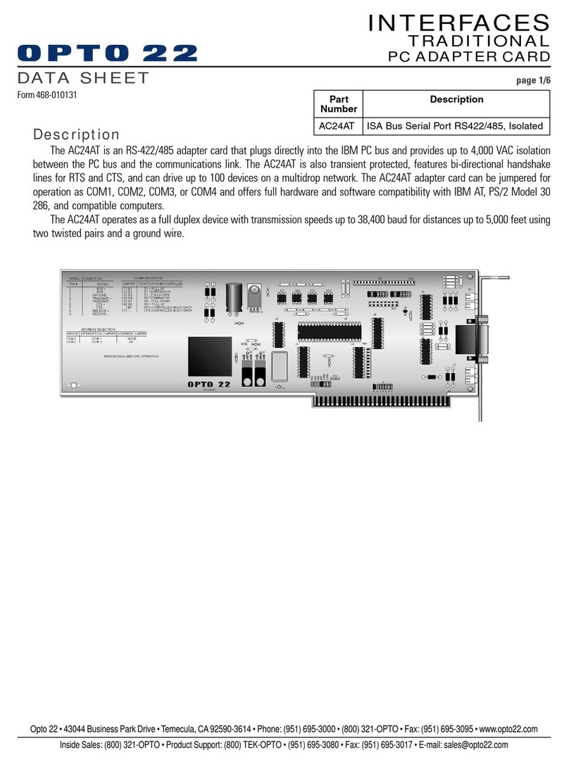
OPTO 22 AC24AT User manual

OPTO 22
OPTO 22 Optomux B1 User manual

OPTO 22
OPTO 22 PCI-AC5 User manual

OPTO 22
OPTO 22 Optomux B1 User manual

OPTO 22
OPTO 22 BD-DEVNET User manual

OPTO 22
OPTO 22 AC24AT User manual

OPTO 22
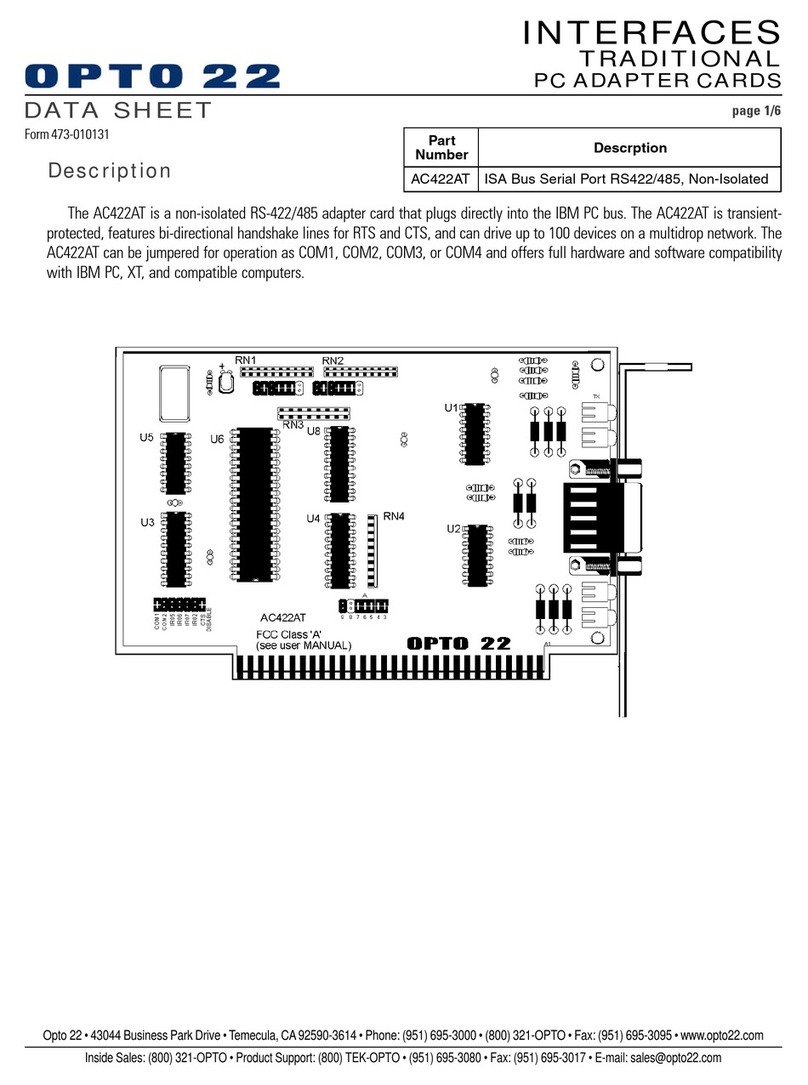
OPTO 22 AC422AT User manual