OPTO 22 PCI-AC51 User manual

PCI-AC51 AND PCIE-AC51
USER’S GUIDE
Form 1459-131106—November 2013
43044 Business Park Drive
•
Temecula
•
CA 92590-3614
Phone: 800-321-OPTO (6786) or 951-695-3000
Fax: 800-832-OPTO (6786) or 951-695-2712
www.opto22.com
Product Support Services
800-TEK-OPTO (835-6786) or 951-695-3080
Fax: 951-695-3017
Email: suppor[email protected]
Web: support.opto22.com

PCI-AC51 and PCIe-AC51 User’s Guide
ii
PCI-AC51 and PCIe-AC51 User’s Guide
Form 1459-131106—November 2013
Copyright © 2003 – 2013 Opto 22.
All rights reserved.
Printed in the United States of America.
The information in this manual has been checked carefully and is believed to be accurate; however, Opto 22 assumes no
responsibility for possible inaccuracies or omissions. Specifications are subject to change without notice.
Opto 22 warrants all of its products to be free from defects in material or workmanship for 30 months from the
manufacturing date code. This warranty is limited to the original cost of the unit only and does not cover installation, labor,
or any other contingent costs. Opto 22 I/O modules and solid-state relays with date codes of 1/96 or newer are guaranteed
for life. This lifetime warranty excludes reed relay, SNAP serial communication modules, SNAP PID modules, and modules
that contain mechanical contacts or switches. Opto 22 does not warrant any product, components, or parts not
manufactured by Opto 22; for these items, the warranty from the original manufacturer applies. These products include,
but are not limited to, OptoTerminal-G70, OptoTerminal-G75, and Sony Ericsson GT-48; see the product data sheet for
specific warranty information. Refer to Opto 22 form number 1042 for complete warranty information.
Wired+Wireless controllers and brains and N-TRON wireless access points are licensed under one or more of the following
patents: U.S. Patent No(s). 5282222, RE37802, 6963617; Canadian Patent No. 2064975; European Patent No. 1142245;
French Patent No. 1142245; British Patent No. 1142245; Japanese Patent No. 2002535925A; German Patent No. 60011224.
Opto 22 FactoryFloor, groov, Optomux, and Pamux are registered trademarks of Opto 22. Generation 4, groov Server,
ioControl, ioDisplay, ioManager, ioProject, ioUtilities, mistic, Nvio, Nvio.net Web Portal, OptoConnect, OptoControl,
OptoDataLink, OptoDisplay, OptoEMU, OptoEMU Sensor, OptoEMU Server, OptoOPCServer, OptoScript, OptoServer,
OptoTerminal, OptoUtilities, PAC Control, PAC Display, PAC Manager, PAC Project, SNAP Ethernet I/O, SNAP I/O, SNAP OEM
I/O, SNAP PAC System, SNAP Simple I/O, SNAP Ultimate I/O, and Wired+Wireless are trademarks of Opto 22.
ActiveX, JScript, Microsoft, MS-DOS, VBScript, Visual Basic, Visual C++, Windows, and Windows Vista are either registered
trademarks or trademarks of Microsoft Corporation in the United States and other countries. Linux is a registered
trademark of Linus Torvalds. Unicenter is a registered trademark of Computer Associates International, Inc. ARCNET is a
registered trademark of Datapoint Corporation. Modbus is a registered trademark of Schneider Electric. Wiegand is a
registered trademark of Sensor Engineering Corporation. Nokia, Nokia M2M Platform, Nokia M2M Gateway Software, and
Nokia 31 GSM Connectivity Terminal are trademarks or registered trademarks of Nokia Corporation. Sony is a trademark of
Sony Corporation. Ericsson is a trademark of Telefonaktiebolaget LM Ericsson. CompactLogix, MicroLogix, SLC, and RSLogix
are trademarks of Rockwell Automation. Allen-Bradley and ControlLogix are a registered trademarks of Rockwell
Automation. CIP and EtherNet/IP are trademarks of ODVA.
All other brand or product names are trademarks or registered trademarks of their respective companies or organizations.
Opto 22
Automation Made Simple.

PCI-AC51 and PCIe-AC51 User’s Guide iii
iii
Table of Contents
Chapter 1: Introduction . . . . . . . . . . . . . . . . . . . . . . . . . . . . . . . . . . . . . . . . . . . . . . . . . . . . . . . . 1
What’s in this Guide. . . . . . . . . . . . . . . . . . . . . . . . . . . . . . . . . . . . . . . . . . . . . . . . . . . . . . . . . . . . . . . . . . . . . . 2
For Help . . . . . . . . . . . . . . . . . . . . . . . . . . . . . . . . . . . . . . . . . . . . . . . . . . . . . . . . . . . . . . . . . . . . . . . . . . . . . . . . . 2
Chapter 2: Installing the Card . . . . . . . . . . . . . . . . . . . . . . . . . . . . . . . . . . . . . . . . . . . . . . . . . . 5
Installing the PCI-AC51 . . . . . . . . . . . . . . . . . . . . . . . . . . . . . . . . . . . . . . . . . . . . . . . . . . . . . . . . . . . . . . . . . . . 5
Installing the PCIe-AC51. . . . . . . . . . . . . . . . . . . . . . . . . . . . . . . . . . . . . . . . . . . . . . . . . . . . . . . . . . . . . . . . . . 6
Chapter 3: Setting Up and Using the SDK . . . . . . . . . . . . . . . . . . . . . . . . . . . . . . . . . . . . . . . 9
Running the SDK Setup Program . . . . . . . . . . . . . . . . . . . . . . . . . . . . . . . . . . . . . . . . . . . . . . . . . . . . . . . . . 9
Using the SDK on Windows 8, Windows 7, and Vista . . . . . . . . . . . . . . . . . . . . . . . . . . . . . . . . . . . . . . 11
SDK Contents . . . . . . . . . . . . . . . . . . . . . . . . . . . . . . . . . . . . . . . . . . . . . . . . . . . . . . . . . . . . . . . . . . . . . . . 11
Using the PamScan Utility . . . . . . . . . . . . . . . . . . . . . . . . . . . . . . . . . . . . . . . . . . . . . . . . . . . . . . . . . . . . 11
Developing an I/O Application . . . . . . . . . . . . . . . . . . . . . . . . . . . . . . . . . . . . . . . . . . . . . . . . . . . . . . . 14
Function Reference for Windows 8, Windows 7, and Vista . . . . . . . . . . . . . . . . . . . . . . . . . . . . .15
Porting Programs Developed with the Older SDK (Using OptoPM32.dll) to Windows 8,
Windows 7, and Vista . . . . . . . . . . . . . . . . . . . . . . . . . . . . . . . . . . . . . . . . . . . . . . . . . . . . . . . . . . .16
Using the SDK on Windows 2000/XP. . . . . . . . . . . . . . . . . . . . . . . . . . . . . . . . . . . . . . . . . . . . . . . . . . . . . 16
SDK Contents . . . . . . . . . . . . . . . . . . . . . . . . . . . . . . . . . . . . . . . . . . . . . . . . . . . . . . . . . . . . . . . . . . . . . . . 17
Pamux Functions . . . . . . . . . . . . . . . . . . . . . . . . . . . . . . . . . . . . . . . . . . . . . . . . . . . . . . . . . . . . . . . . . . . . 17
Required Function Calls . . . . . . . . . . . . . . . . . . . . . . . . . . . . . . . . . . . . . . . . . . . . . . . . . . . . . . . . . 17
Naming Conventions . . . . . . . . . . . . . . . . . . . . . . . . . . . . . . . . . . . . . . . . . . . . . . . . . . . . . . . . . . . . 17
Banks and Points . . . . . . . . . . . . . . . . . . . . . . . . . . . . . . . . . . . . . . . . . . . . . . . . . . . . . . . . . . . . . . . .17
Common Function Parameters and Return Values . . . . . . . . . . . . . . . . . . . . . . . . . . . . . . . .17
Developing an I/O Application . . . . . . . . . . . . . . . . . . . . . . . . . . . . . . . . . . . . . . . . . . . . . . . . . . . . . . . 18
Special Directions for Visual Basic Programmers . . . . . . . . . . . . . . . . . . . . . . . . . . . . . . . . . .18
Special Directions for Visual C++ Programmers . . . . . . . . . . . . . . . . . . . . . . . . . . . . . . . . . . . 18
Function Reference for Windows 2000/XP . . . . . . . . . . . . . . . . . . . . . . . . . . . . . . . . . . . . . . . . . . . .19
PCI-AC51 or PCIe-AC51 Operations . . . . . . . . . . . . . . . . . . . . . . . . . . . . . . . . . . . . . . . . . . . . . .19
Digital Bank Operations . . . . . . . . . . . . . . . . . . . . . . . . . . . . . . . . . . . . . . . . . . . . . . . . . . . . . . . . .20
Digital Point Operations . . . . . . . . . . . . . . . . . . . . . . . . . . . . . . . . . . . . . . . . . . . . . . . . . . . . . . . . .21
Digital “Fast” Operations . . . . . . . . . . . . . . . . . . . . . . . . . . . . . . . . . . . . . . . . . . . . . . . . . . . . . . . . .21
Analog Bank Operations . . . . . . . . . . . . . . . . . . . . . . . . . . . . . . . . . . . . . . . . . . . . . . . . . . . . . . . . .22
Analog Point Operations . . . . . . . . . . . . . . . . . . . . . . . . . . . . . . . . . . . . . . . . . . . . . . . . . . . . . . . . 22
Analog Watchdog Operations . . . . . . . . . . . . . . . . . . . . . . . . . . . . . . . . . . . . . . . . . . . . . . . . . . .23

PCI-AC51 and PCIe-AC51 User’s Guide
iv
Analog Status Operations . . . . . . . . . . . . . . . . . . . . . . . . . . . . . . . . . . . . . . . . . . . . . . . . . . . . . . . 23
Pamux Utility Operations . . . . . . . . . . . . . . . . . . . . . . . . . . . . . . . . . . . . . . . . . . . . . . . . . . . . . . . . . . . . 24
Bit Operations . . . . . . . . . . . . . . . . . . . . . . . . . . . . . . . . . . . . . . . . . . . . . . . . . . . . . . . . . . . . . . . . . . 24
Pack/Unpack Utility Operations . . . . . . . . . . . . . . . . . . . . . . . . . . . . . . . . . . . . . . . . . . . . . . . . . 24
Scaling Operations . . . . . . . . . . . . . . . . . . . . . . . . . . . . . . . . . . . . . . . . . . . . . . . . . . . . . . . . . . . . . 25
Pamux Bus Reset Line . . . . . . . . . . . . . . . . . . . . . . . . . . . . . . . . . . . . . . . . . . . . . . . . . . . . . . . . . . . . . . . . . . . 26
Purpose of the Reset Line . . . . . . . . . . . . . . . . . . . . . . . . . . . . . . . . . . . . . . . . . . . . . . . . . . . . . . . . . . . 26
Reset Line Voltage . . . . . . . . . . . . . . . . . . . . . . . . . . . . . . . . . . . . . . . . . . . . . . . . . . . . . . . . . . . . . . . . . . 26
Terminology . . . . . . . . . . . . . . . . . . . . . . . . . . . . . . . . . . . . . . . . . . . . . . . . . . . . . . . . . . . . . . . . . . . . . . . . 26
“LOW” and “HIGH” . . . . . . . . . . . . . . . . . . . . . . . . . . . . . . . . . . . . . . . . . . . . . . . . . . . . . . . . . . . . . . 26
Brain Reset Configuration: “Active HIGH” and “Active LOW” . . . . . . . . . . . . . . . . . . . . . . . 26
Special Precautions for the Software Developer . . . . . . . . . . . . . . . . . . . . . . . . . . . . . . . . . . . . . . . . . . . 27
Appendix A: Error Codes . . . . . . . . . . . . . . . . . . . . . . . . . . . . . . . . . . . . . . . . . . . . . . . . . . . . . .29
Error Messages for Windows 8, Windows 7, and Vista. . . . . . . . . . . . . . . . . . . . . . . . . . . . . . . . . . . . . . 29
Error Codes for Windows 2000/XP. . . . . . . . . . . . . . . . . . . . . . . . . . . . . . . . . . . . . . . . . . . . . . . . . . . . . . . . 29
Appendix B: Requirements, Specifications, & LEDs . . . . . . . . . . . . . . . . . . . . . . . . . . . . .33
System Requirements . . . . . . . . . . . . . . . . . . . . . . . . . . . . . . . . . . . . . . . . . . . . . . . . . . . . . . . . . . . . . . . . . . . 33
Specifications . . . . . . . . . . . . . . . . . . . . . . . . . . . . . . . . . . . . . . . . . . . . . . . . . . . . . . . . . . . . . . . . . . . . . . . . . . . 33
LEDs . . . . . . . . . . . . . . . . . . . . . . . . . . . . . . . . . . . . . . . . . . . . . . . . . . . . . . . . . . . . . . . . . . . . . . . . . . . . . . . . . . . . 34
PCI-AC51 . . . . . . . . . . . . . . . . . . . . . . . . . . . . . . . . . . . . . . . . . . . . . . . . . . . . . . . . . . . . . . . . . . . . . . . . . . . 34
PCIe-AC51 . . . . . . . . . . . . . . . . . . . . . . . . . . . . . . . . . . . . . . . . . . . . . . . . . . . . . . . . . . . . . . . . . . . . . . . . . . 35
Appendix C: Converting Applications to a Newer Card . . . . . . . . . . . . . . . . . . . . . . . . .37
Applications that Used the OptoPMUX.DLL for the AC5 . . . . . . . . . . . . . . . . . . . . . . . . . . . . . . . . . . . 37
Converting Applications that Use Inp( ) and Outp( ) . . . . . . . . . . . . . . . . . . . . . . . . . . . . . . . . . . . . . . . 37
Appendix D: PCI-AC51 and PCIe-AC51 Technical Reference . . . . . . . . . . . . . . . . . . . . .39
Architecture. . . . . . . . . . . . . . . . . . . . . . . . . . . . . . . . . . . . . . . . . . . . . . . . . . . . . . . . . . . . . . . . . . . . . . . . . . . . . 40
Adapter Card Identification . . . . . . . . . . . . . . . . . . . . . . . . . . . . . . . . . . . . . . . . . . . . . . . . . . . . . . . . . . . . . . 40
Adapter Card Base Address Configuration . . . . . . . . . . . . . . . . . . . . . . . . . . . . . . . . . . . . . . . . . . . . . . . . 40
BAR1 Register Table . . . . . . . . . . . . . . . . . . . . . . . . . . . . . . . . . . . . . . . . . . . . . . . . . . . . . . . . . . . . . . . . . 40
Register Description . . . . . . . . . . . . . . . . . . . . . . . . . . . . . . . . . . . . . . . . . . . . . . . . . . . . . . . . . . . . . . . . . . . . 41
Powerup Conditions. . . . . . . . . . . . . . . . . . . . . . . . . . . . . . . . . . . . . . . . . . . . . . . . . . . . . . . . . . . . . . . . . . . . . 42
Controlling the Reset Line . . . . . . . . . . . . . . . . . . . . . . . . . . . . . . . . . . . . . . . . . . . . . . . . . . . . . . . . . . . . . . . 42
Controlling the Reset Line Using the Pamux Driver . . . . . . . . . . . . . . . . . . . . . . . . . . . . . . . . . . . 42
Controlling the Reset Line When Not Using the Pamux Driver . . . . . . . . . . . . . . . . . . . . . . . . . 42
Default Power-Up State of Reset Line . . . . . . . . . . . . . . . . . . . . . . . . . . . . . . . . . . . . . . . . . . . . . . . . 43
Reset Configuration of Brains When Using PamScan . . . . . . . . . . . . . . . . . . . . . . . . . . . . . . . . . . 43
Testing . . . . . . . . . . . . . . . . . . . . . . . . . . . . . . . . . . . . . . . . . . . . . . . . . . . . . . . . . . . . . . . . . . . . . . . . . 43
DIP Switches (PCI-AC51) and Jumpers (PCIe-AC51). . . . . . . . . . . . . . . . . . . . . . . . . . . . . . . . . . . . . . . . 43
Strobe Duration . . . . . . . . . . . . . . . . . . . . . . . . . . . . . . . . . . . . . . . . . . . . . . . . . . . . . . . . . . . . . . . . . . . . . . . . 44
High and Low Latency Modes . . . . . . . . . . . . . . . . . . . . . . . . . . . . . . . . . . . . . . . . . . . . . . . . . . . . . . . . . . . 44

PCI-AC51 and PCIe-AC51 User’s Guide v
v
Performing Pamux Operations . . . . . . . . . . . . . . . . . . . . . . . . . . . . . . . . . . . . . . . . . . . . . . . . . . . . . . . . . . 44
Issuing Pamux Reset . . . . . . . . . . . . . . . . . . . . . . . . . . . . . . . . . . . . . . . . . . . . . . . . . . . . . . . . . . . . . . . . 44
Reading the State Machine Version . . . . . . . . . . . . . . . . . . . . . . . . . . . . . . . . . . . . . . . . . . . . . . . . . . 45
Reading the Switch Values . . . . . . . . . . . . . . . . . . . . . . . . . . . . . . . . . . . . . . . . . . . . . . . . . . . . . . . . . . 45
Polled PCI-AC51 and PCIe-AC51 Operation . . . . . . . . . . . . . . . . . . . . . . . . . . . . . . . . . . . . . . . . . . .45
Performing a Pamux Bank Write . . . . . . . . . . . . . . . . . . . . . . . . . . . . . . . . . . . . . . . . . . . . . . . . .45
Performing a Pamux Bank Read . . . . . . . . . . . . . . . . . . . . . . . . . . . . . . . . . . . . . . . . . . . . . . . . .46
Notes for the SNAP-B6 (Digital Aspect) . . . . . . . . . . . . . . . . . . . . . . . . . . . . . . . . . . . . . . . . . . . . . . . . . . 46

PCI-AC51 and PCIe-AC51 User’s Guide
vi

PCI-AC51 and PCIe-AC51 User’s Guide
1
1
Chapter 1
1: Introduction
The PCI-AC51 and PCIe-AC51 adapter cards bring industry-standard Pamux
®
to modern computers
that use the Peripheral Component Interconnect (PCI) or PCI Express (PCIe) local bus.
•The PCI-AC51 is compatible with computers that feature a 5.0 or 3.3 volt PCI bus.
•The PCIe-AC51 is compatible with computers using the PCI Express bus.
These cards are an ideal choice for customers who must replace an older ISA bus-based PC that
currently uses an Opto 22 AC28 adapter card.
NOTE: The PCI-AC28 is not recommended for new designs. Use the PCI-AC51 or the PCIe-AC51 instead.
Using the PCI-AC51 or PCIe-AC51 adapter card, your computer can communicate with Opto 22
classic B4, B5, and B6 brain boards and with SNAP-B4 and SNAP-B6 brains.
•Each Pamux bus can access up to 32 remote brains.
•Each Pamux bus supports up to 512 points.
Free with these adapter cards is the Pamux Systems SDK, included on the CD that came with the
card and also available on our website, www.opto22.com. The Pamux Systems SDK supports up to
32 adapter cards. Two SDKs are included on the CD:
• Windows 8, Windows 7, and Vista operating systems—samples, source code, and the
driver. This SDK supports C#, VB.NET and other .NET languages. Existing applications n VB and
Visual C++ can be updated to Win 7 using this SDK.
• Microsoft Windows XP and 2000 operating systems—sample applications, utility
applications, and the driver. This SDK supports Microsoft Visual Basic (version 6) and Microsoft
Visual C++ (version 6). .
Use the DLL file for your OS, application, and language:
For this OS: Windows 8, Windows 7, and Vista Windows
95/98/ME/NT/2000/XP
For existing or
new application: Existing app New app in
C++
New app in C# or
other .NET language Existing app New app in VB6
or Visual C++
Use this DLL file: OptoPM32.dll OptoPM32.dll PCIAC5.dll OptoPM32.dll OptoPM32.dll

WHAT’S IN THIS GUIDE
PCI-AC51 and PCIe-AC51 User’s Guide
2
What’s in this Guide
This guide assumes that you are familiar with Pamux and the brains, racks, and input/output
modules used with Pamux. For more information on Pamux, see Opto 22 form 726, the Pamux User’s
Guide. If you are going to program the PCI-AC51 or PCIe-AC51 using the Pamux Systems SDK, this
guide assumes that you are already familiar with programming in Microsoft.NET, Microsoft
®
Visual
Basic
®
, or Visual C++
®
.
This guide includes the following chapters and appendixes:
Chapter 1: Introduction introduces the card and provides Product Support information.
Chapter 2: Installing the Card describes how to install the adapter card before you install the SDK
software.
Chapter 3: Setting Up and Using the SDK describes how to set up and use the SDK.
Appendix A: Error Codes lists and describes the error codes that you might encounter when
working with the Pamux Systems SDK.
Appendix B: Requirements, Specifications, & LEDs provides system requirements and
specifications for the PCI-AC51 and PCIe-AC51 adapter cards. It also shows the location and function
of card LEDs.
Appendix C: Converting Applications to a Newer Card describes how to convert applications
that used the AC28 and PCI-AC28 adapter cards.
Appendix D: PCI-AC51 and PCIe-AC51 Technical Reference provides technical information for
authoring a device driver for an unsupported operating system or a Windows kernel-mode driver.
For Help
If you have problems installing or programming the PCI-AC51 or PCIe-AC51 adapter card and
cannot find the help you need in this guide, contact Opto 22 Product Support.
Phone: 800-TEK-OPTO (800-835-6786)
951-695-3080
(Hours are Monday through Friday,
7 a.m. to 5 p.m. Pacific Time)
Fax: 951-695-3017
Email: suppor[email protected]
Opto 22 website: www.opto22.com
When calling for technical support, be prepared to provide the following information about your
system to the Product Support engineer:
•PC configuration (type of processor, speed, memory, operating system, and service packs)
•A complete description of your hardware and operating systems, including:
– additional accessories installed (such as sound cards, NICs, etc.)
–typeofpowersupply
– types of I/O units installed
NOTE: Email messages and phone
calls to Opto 22 Product Support
are grouped together and
answered in the order received.

CHAPTER 1: INTRODUCTION
PCI-AC51 and PCIe-AC51 User’s Guide
3
3
– third-party devices installed (for example, barcode readers)
•Software and version being used
•Specific error messages and/or numbers seen.

FOR HELP
PCI-AC51 and PCIe-AC51 User’s Guide
4

PCI-AC51 and PCIe-AC51 User’s Guide
5
5
Chapter 2
2: Installing the Card
Follow the steps below to install the PCI-AC51 or PCIe-AC51 adapter card before you install the SDK
software. Use any available expansion slot on the computer.
You may add multiple adapter cards for convenience, but note that multiple cards do not increase
Pamux throughput. The number of Pamux accesses per computer is constant. Note the power
requirements listed in the Specifications table on page 33.
Choose the installation steps for your card:
Installing the PCI-AC51
IMPORTANT:
Install the adapter card before you install the SDK software.
You can install the PCI-AC51 adapter card into any PCI expansion slot on your computer.
1. Turn off the computer. Remove the power cord and the computer’s cover.
The power cord must be removed, as a sudden spike may cause the computer to boot.
2. Before handling the card, discharge excess static electricity by touching the computer’s metal
chassis.
3. Install the card in the expansion slot. Verify that the card is properly seated in the motherboard
socket. Secure the card with the screw.
4. Attach the cable to the adapter card. Connect the other end of the cable to the I/O mounting
rack. See page 28, for cable part numbers and pinouts.
Installing the PCI-AC51
Installing the PCIe-AC51
page 5
page 6

INSTALLING THE PCIE-AC51
PCI-AC51 and PCIe-AC51 User’s Guide
6
CAUTION: Do not scratch this card or other cards in the computer, as scratching may irreversibly
damage the card or other devices.
5. Reinstall the power cord. If you wish, leave the computer cover off temporarily to see the card’s
LEDs.
6. Turn on the computer.
Because the card is self-configuring, it has no jumpers. Configuration is automatically
performed by the BIOS when the card is installed.
If you are using Windows Vista or an earlier version of Windows and a “Found New Hardware”
message appears, simply click Cancel. The setup program will install the device driver
automatically.
If you have been using an AC28 adapter card for the ISA bus, you will need to make some changes
to your application because of the new adapter card. See Appendix C: Converting Applications to a
Newer Card for specific information.
Installing the PCIe-AC51
IMPORTANT:
Install the adapter card before you install the SDK software.
On your computer, install the PCIe-AC51 into any PCIe expansion slot.
1. Turn off the computer. Remove the power cord and the computer’s cover.
The power cord must be removed, as a sudden spike may cause the computer to boot.
2. Before handling the card, discharge excess static electricity by touching the computer’s metal
chassis.
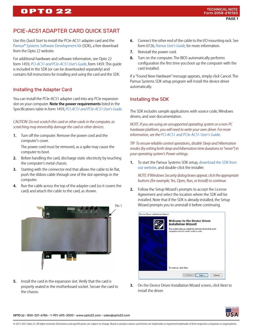
3. Starting with the connector end that allows the cable to lie flat, push the ribbon cable through
one of the slot openings in the computer.
4. Run the cable across the top of the adapter card (so it covers the card) and attach the cable to
the card, as shown.
Pin 1 Example: PCI-AC51

CHAPTER 2: INSTALLING THE CARD
PCI-AC51 and PCIe-AC51 User’s Guide
7
7
5. Install the card in the expansion slot. Verify that the card is properly seated in the motherboard
socket. Secure the card with the screw.
6. Connect the other end of the cable to the I/O mounting rack. See page 28, for cable part
numbers and pinouts.
CAUTION: Do not scratch this card or other cards in the computer, as scratching may irreversibly
damage the card or other devices.
7. Reinstall the computer’s cover and power cord.
8. Turn on the computer.
Configuration is automatically performed by the BIOS when the card is installed.
If you are using Windows Vista or an earlier version of Windows and a “Found New Hardware”
message appears, simply click Cancel. The Pamux Systems SDK setup program will install the
device driver automatically.
If you have been using an AC28 adapter card for the ISA bus, you will need to make some changes
to your application because of the new adapter card. See Appendix C: Converting Applications to a
Newer Card for specific information.
Pin 1

INSTALLING THE PCIE-AC51
PCI-AC51 and PCIe-AC51 User’s Guide
8

PCI-AC51 and PCIe-AC51 User’s Guide
9
9
Chapter 3
3: Setting Up and Using the SDK
This chapter describes how to set up and use the Pamux Systems SDK. Before you install the SDK
software, first make sure to install the adapter card. See Chapter 2: Installing the Card.
In this chapter:
Running the SDK Setup Program .......................................................... page 9
Using the SDK on Windows 8, Windows 7, and Vista ................page 11
Using the SDK on Windows 2000/XP................................................page 16
Pamux Bus Reset Line...............................................................................page 26
Special Precautions for the Software Developer ..........................page 27
NOTE: Version 2.0 and higher support only the PCI-AC51 or PCIe-AC51—not the AC28 and PCI-AC28
adapter cards.
Running the SDK Setup Program
The Pamux Systems SDK comes on the CD with the card. If you do not have the CD, you can order it
through Product Support, or you can download the SDK free from our website, www.opto22.com.
The SDK includes a sample application, Windows drivers, and user documentation.
NOTE: If you are using a different operating system or a non-PC hardware platform, you will need to write
your own driver. See Appendix D: PCIe/PCI-AC5 Register Set and Memory Locations and Appendix E: AC5
Hardware Description for more information.
1. Insert the CD in your CD-ROM drive to start the Pamux Systems SDK setup wizard.
2. Follow the wizard’s instructions.
3. On the Select Components screen, select your computer’s operating system.

RUNNING THE SDK SETUP PROGRAM
PCI-AC51 and PCIe-AC51 User’s Guide
10
For Windows 8, Windows 7, and Vista, choose the 64-bit version or the 32-bit version.
`
4. If a Windows Security dialog box appears, click the Run or Install button to continue.
Select the operating system

CHAPTER 3: SETTING UP AND USING THE SDK
PCI-AC51 and PCIe-AC51 User’s Guide
11
11
NOTE: If you have already installed the driver for another adapter card, you will receive an error that there
is currently an open application using WinDriver. If this happens, simply click Cancel to continue installing.
5. When setup is complete, click the Finish button.
Using the SDK on Windows 8, Windows 7, and Vista
SDK Contents
The Pamux Systems SDK includes a driver, sample applications, and tools to help you develop
applications for the PCI-AC51 or PCIe-AC51 adapter card and integrate it with your system. The SDK
saves you time and effort that would otherwise be spent learning the intricacies of the Pamux bus
structure.
The SDK supports C#, VB.NET and other .NET languages
NOTE: Version 2.0 and higher support only the PCI-AC51 or PCIe-AC51—not the AC28 and PCI-AC28
adapter cards.
Using the PamScan Utility
The PamScan utility is available on the Windows Start menu. It demonstrates turning digital points
on and off and configuring points as either input or output. In addition, analog point values can be
displayed and output values can be changed. PamScan is written in C# and all the source code is
included.
NOTE: Instructions are the same for the PCI-AC51 and the PCIe-AC51, although only the PCI-AC51 is
shown.
To use PamScan:
1. Select Start > All Programs > Opto 22 > PCI-AC51 > PamScan.exe

USING THE SDK ON WINDOWS 8, WINDOWS 7, AND VISTA
PCI-AC51 and PCIe-AC51 User’s Guide
12
2. Make sure the reset level matches the reset level configured on the Pamux brain.
3. If you have more than one PCI-AC51 or PCIe-AC51card installed, click the card selector button.
NOTE: Normally you will use the default Adapter Card ID, which is 0.
4. In the dialog box that opens, select a card.
5. Optional Step—Flash LEDs: This step is optional because it requires you to open your computer and
see the LEDs on the card.
a. With your computer open so that you can see the LEDs, choose the card, and then click the
Flash LEDs button.
b. Notice the result on the card’s LEDs.
The program flashes the LEDs five times. If no flashing occurs, you may have selected the
wrong card. Select the next card in the list and click the Flash LEDs button again.
6. Click OK to close the dialog box. In PamScan, click Open Adapter Card.
This screen shows all four banks available on a 32-channel Pamux board. Each bank has eight
I/O points and has a unique address. For example, the banks shown here have addresses 0, 1, 2,
and 3 on the attached I/O mounting rack.
Reset level
Card selector button
Click Open Adapter Card

CHAPTER 3: SETTING UP AND USING THE SDK
PCI-AC51 and PCIe-AC51 User’s Guide
13
13
7. Choose a bank on the Pamux mounting rack that has I/O installed. Then in the PamScan
window, make sure the address matches the bank’s address on the mounting rack.
In the following example, 5 is entered as the address to match the address on the
mounting rack:
8. Select the I/O type, either Analog or Digital.
9. For output modules: select each point that is an output, then click Configure Selected Points As
Outputs.
The first bank on
the attached rack
has an address of 0
Match the bank’s
address on the rack
Select the I/O type

USING THE SDK ON WINDOWS 8, WINDOWS 7, AND VISTA
PCI-AC51 and PCIe-AC51 User’s Guide
14
Notice that the selected points change to “Output.”
For input modules: when an input changes state, its value will be updated in the display.
10. With the same output points selected, click Turn Selected Output Points On.
Notice that the selected output points change from “Off” to “On.”
11. Continue to experiment as you like with selecting points, configuring points as inputs or
outputs, and turning points on and off.
Developing an I/O Application
Before you begin:
•Add the PCIAC51.dll as a reference to your project.
Select outputs
Click here
The selected points
change to “Output”
Click here
The selected points
change to “On”
Other manuals for PCI-AC51
2
This manual suits for next models
1
Table of contents
Other OPTO 22 PCI Card manuals