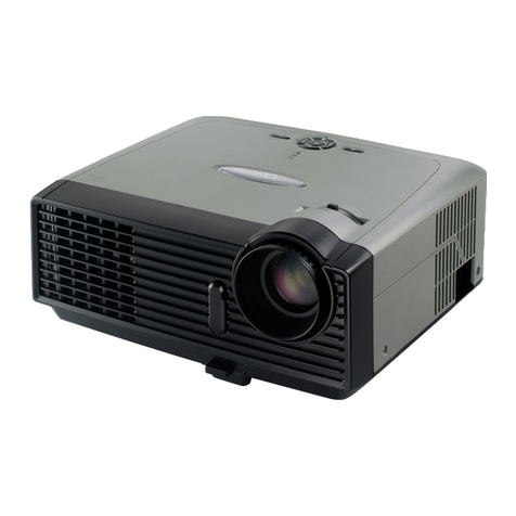
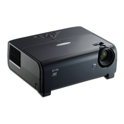
Optoma EzPro 710 User manual

~PREFACE~
This manual is prepared for the maintenance service forDMD Projec-
tor series. Maintenance procedures described in this manual are intended to
isolate faulty parts and replace them in the field. It also aims to serve as a guide
in procuring replacement parts for this product.
This manual is copyrighted and all rights are reserved. This product may
not, in whole or in part, be copied, photocopied, translated or reduced to any
electronic or machine readable form without prior written consent except for
copies retained by the purchaser for backup purpose.
This manual includes system overview, major system assembly, com-
ponents’ description, and the “Troubleshooting” makes explanations on how to
detect errors. It also includes a flow chart for checking or correcting faults.
No Warranty or representation, either expressed or implied, is made
with respect to this documentation, its quality, performance, merchant-
ability or fitness for particular purpose.
No event will the vendor be liable for direct, indirect, special, inci-
dental or consequential damages arising out of the user or inability to use
this product or documentation.
PNOTICE
The information found in this manual is subject to change without prior
notice. Any subsequent changes made to the data herein will be incorporated
in future edition
.
Model Name: EzPro 710
All Rights Reserved
Manual Version 1.0
Document #814-G04-01A

✽Table of Contents ✽
1. Introduction 1-1
1.1 ProductHighlight 1-1
1.2 Mechanical Specification 1-2
2. Fundamental Principle 2-1
2.1 Operating of Projector 2-1
2.2 User Control and Indicators 2-3
2.3 Optics of Projector 2-5
2.4 System 2-7
3. Mechanical Construction 3-1
3.1 Package Overview 3-1
3.2 Exploded Overview 3-3
3.3 Spare Parts Lists of Recommadation 3-9
4. Procedure of Disassembly 4-1
4.1 Disassemble Lamp Module 4-1
4.2 Disassemble the Main Body Unit 4-2
4.3 Dissassemble the DC-Dc Board 4-3
4.4 Disasemble Control Panel Module 4-4
4.5 Disassemble Engine and Electronic Module 4-5
4.6 Disassemble Main Board and DMDModule 4-6
4.7 Disassemble Lamp holder Module 4-6
4.8 Disassemble Ballast Module 4-8

5. Functions of Boards 5-1
5.1 Main Board 5-1
5.2 DC-DC Power Supply 5-7
5.3 KeyPad Board 5-10
5.4 DMD Module 5-11
6. Function Test & Alignment Procedure 6-1
6.1 Product 6-1
6.2 Test Equipment 6-1
6.3 Test Condition 6-1
6.4 Test Display Modes& Pattern 6-2
6.5 Function Test andAlignment Procedure 6-5
6.6 Hi-Pot &Grounding Test 6-7
6.7 Cleaning 6-7
6.8 EP 710 Display Specification Test Procedure 6-8
7. Troubleshooting Procedure 7-1
7.1 Equipment Needed 7-1
7.2 Main Procedure 7-1
8. Specification 8-1
8.1 DMD Specification 8-1
8.2 Lamp Specification 8-3
9. Appendix 9-1
9.1 Compatibility Modes 9-1
9.2 The SeriesNumber SystemDefinition 9-2

EzPro 710 1-1
Service Manual
EzPro710
Service Manual
One panel 0.9”DMDprojection system with 600ANSI
lumens,90 uniformity.
120-Watt Compact UHP Lamp.( user replaceable)
High efficiency cooling system with system acoustic
less than 42dB.
Light weight less than 5 lbs.
Manual focus projection lens.
True 1024*768 resolution,True Colors.
With up, down, left, and right screen reverse.
Build-in full screenNTSC/PAL/SECAM video capability
with composite and S-video terminals.
XGA/SVGA/VGA/MAC/PC98/FM Towns compatibility
with XGAcompression/pan.
Auto image re-sizing to 1024*768 full screen.
Auto detection of computer signal input.
AutoImage.(Auto-tracking/frequency/contrast/brightness/
position adjustment)
Powerful enlarge and freeze function
Automatically saves adjustments for future use
On-screen menu with more than 6 languages.
On Screen lamp life timer.
OneD-sub PC-data input.
Built-in one speaker with 3 Watt amplifier.
Self protect( 45 seconds) timer for hot re-strike of
UHPlamp.
Wireless remote controller.
1.1 Product Highlight
Chapter 1
Introduction
-
-
-
-
-
-
-
-
-
-
-
-
-
-
-
-
-
-
-
-
-

EzPro 710 1-2
Service Manual
EzPro710
Service Manual
1.2 Mechanical Specification
Light Valve
Contrast Radio
Lamp
Displayable Color
Projection Lens
Projection Screen Size
Computer Compatibility
Single ChipDMDTechnology
400:1(FullOn/FullOff)
200:1(ANSI Contrast)
120W User Replaceable UHP Lamp
16.7 M colors
F2.88 f=30.7mm
30’ (1m)~300’(10m) Diagonal
IBM &VESA VGA 640*350,70/85Hz
640*480,70/85Hz
720*400,70/85Hz
640*480,60/72/75/85Hz
800*600,56/60/72/75/85Hz
VESAXGA 1024*768,60/70/75/85Hz
Apple Macintosh LC 13” 1280*1024 compressed 60/75Hz
Apple Macintosh II 13” 640*480,67Hz
Apple Macintosh 16” 640*480,67Hz
Apple Macintosh 19” 832*624,75Hz
NEC PC-98 series 1024*768,75Hz
640*400,56Hz
640*480,60/70Hz
Fujitsu FM Towns 640*400,55Hz
640*480,60Hz
Video Compatibility
H.Frequency
V. Frequency
MultimediaAudio
NTSC/NTSC 4.43/PAL/SECAM compatibility
Composite video& S-Video capability
30kHz~90kHzhorizontal scan
50Hz~85Hzverticalrefresh
One internal speaker with 3 watt output

EzPro 710 1-3
Service Manual
EzPro710
Service Manual
Dimensions(W*H*D)
Environmental
Power Supply
Power Consumption
I/O Connectors
AC input 90~264VAuto-Switching Power Supply
<185W
Power:AC Power Input Socket
Computer Input:One 15-pinD-sub Computer Input
Video Input: One Composite Video RCA Input
One S-Video Input
Audio Input: One Phone Jack forAudio Input
Audio Output: One Phone Jack forAudio Line Input
5 lbs./2.3 kgs
3.54*8.58*9.9 inches/90*218*252 mm
Temperature
-Operating: 10 C to + 40 C
-Storge: -20 C to + 60 C
Maximum Humidity
-Operating: 10 C to + 40 C -- 80% RH, ono-condensing
-Storage: -20 C + 60 C -- 80%RH, non-condensing
Acoustic noise level
-42dB typical/45dB maximum
Lamp life
-2000 hours typital
Altitude
-Operating 10,000ft
-Storge 40,000ft
MTSF
-Operating more than 10,000 hours
FCC Class B, CE Mark classAB VCCI-1
UL, CUL, TUV, BCIQ
Regulation

EzPro 710 2-1
Service Manual
EzPro710
Service Manual
Chapter 2
Fundamental Principle
2.1 Operating of Projector
Language —— Select display from six languages in their native spelling.
The current language is highlighted. Select another language to display all
menufunctionsin that language.
Display
Brightness and Contrast
-----Adjust the displayed image brightness and contrast
Color
----- Adjust color balance to compensate for ambient conditions
using three submenus:
7100oK ——The factory default
Custom Color —— Modify the color temperature balance.
Saturation —— Magnify the color intensity.
Keystone
----Adjust image distortion caused by tilting the projector. The
only adjustment direction allowed is to narrow the top width
of the image.
Image
Freeze
----To freeze the display of the current image.
Note:
a. Press the Freeze key again to unfreeze the display.
b. The “ Freeze Screen” should have an icon to indicate
the curent display has been frozon
❒
❒
❒
❍
❍
❍
❍
◆
◆
◆
2.1.1 Fuctions in the On-Screen Menu

EzPro 710 2-2
Service Manual
EzPro710
Service Manual
Track To adjust Phase of Sampling Clock
To avoid A/D converter to capture trasition of input signal
Frequency
To adjust total number of pixel clock in one line period.
Auto Image
For automatic tracking/frequnecy/position adjustment,
enable in “on” state, and disable in “off” state.( Data only)
----
----
----
----
❍
❍
❍
Audio Adjust the tone & Volume
Projection Select the project method & picture in picture fuction.
Lamp Warning & Reset
When lamp’s life end, it will show a warning message.
When replace a new lamp, reset the lamp hour.
❒
2.1.2
Service Manu
Use to enter Service Manu
Color wheel ------Adjust the index to charge the color combination
BurnIn -------------Supply burnin function
Luminance masure ---- Supply luminance measure function
Color Bar --------- Supply R,G,B picture
Lamp hours ------ lamp hours can be adjusted here
Focus --------------Supply text to adjust focus

EzPro 710 2-3
Service Manual
EzPro710
Service Manual
2.2 User Control and Indicators
There are two ways for you to control the functions: Remote Control and
Panel Control.
Remote Control Panel Control
Power / Standby
Power the lamp on and off when the main power switch is turned on.
Menu
Press to open the on-screen display (OSD) menus and to switch
amoung different menus. To exit OSD, select the “ Exit Menu” icon and press
“Enter” button. The projector saves any changes you made automatically.
Source
Press “Source” to choose between video and computer sources.
Reset
When you press “Reset” button, the OSDmenus shows message “Reset All
Yes/NO ? ”. Select “Yes” to confirm or select “ No” to cancel.This function
will reset all user adjustable parameters to factory default settings.

EzPro 710 2-4
Service Manual
EzPro710
Service Manual
Enter
Press “Enter” for confirming your selection.
Four Directional Select Keys
Use or to select items. Use or to make adjustments
for your selection.
Volume
To increase the volume, press
To decrease the volume, press
To mute the volume, press
Resync
Automatically synchronizes the projector to the input source.
Freeze
Press “freeze” button to still the screen image.
PIP (Picture in Picture)
Display video source image on a small screen. (Computer mode only).
Please refer to “Page 20” for detail informations.
Zoom In (Computer mode only)
Magnifies an image up to a factor of 32 on the projection screen.
When the “Zoom” icon displayed, you can use four directional select keys
to change the vertical or horizontal positioning of the image.
Zoom Out (Computer mode only)
Diminishes the zoom in image.
When the “Zoom” icon displayed, you can use four directional select keys to
change the vertical or horizontal positioning of the image.
Keystone
Adjusts image distortion caused by tilting the projector.

EzPro 710 2-5
Service Manual
EzPro710
Service Manual
2.3 Optics of Projector
2.3.1 Conceptual Drawing
1. Projection Lens 7. Plastic (PMMA) Condenser Lens
2. TIR Prism 8. UV-IR Filter
3. DMD Module 9. Hollow Integration Rod
4. Plastic (PMMA) Relay Lens 10. Color Wheel
5. Enhance Mirror 11. AR Coating Condenser
6. Enhance Mirror 12. OSRAM Elliptical Reflector
UHP Lamp 120W

EzPro 710 2-6
Service Manual
EzPro710
Service Manual
2.3.2 Basic Function
❑❑
❑❑
❑Projection Lens Projecting image on the screen
❑❑
❑❑
❑Enhance Mirror Folding optical path.
❑❑
❑❑
❑Elliptical Reflector The light source.
UHP Lamp 120W
❑❑
❑❑
❑Plastic Condenser Condensing the light beam.
Lens
❑❑
❑❑
❑Hollow Making the light beam uniform.
Integration Rod
❑❑
❑❑
❑UV-IR Filter Filtering UV-IR out.
❑❑
❑❑
❑Plastic Relay Lens Lengthening optical path.
❑❑
❑❑
❑TIR Prism Reflecting all light beams inside.
❑❑
❑❑
❑Color Wheel Separating the light beam into
and produce R.G.B colors.
❑❑
❑❑
❑AR Coating Condensing the light beam.
Condenser
❑❑
❑❑
❑DMD Module Displaying component.

EzPro 710 2-7
Service Manual
EzPro710
Service Manual
2.4 System
2.4.1 Block Diagram
Memory
Image
Processor
PW264
9984
APC
VGAIN
7114
Decoder
MIS
MCLK
DCLK
Reset
Config/Sequence
PROM
Lamp
Module
L.P.S Cooling
System
DC-DC
Module
Control
FPGA
Micro
Controller
Data Path
formatter
VCC2,VOFFSET
VBIAS,VRESET
GENERATION RESET
ASIC
DMD
SDRAM SDRAM
Color
Wheel
Control Color wheel driver
Start-20Kv.
Normal 80~120V
AC
90~132
195~255
400Vdc
OSC
EEPROM
VVS,VHS,
VPEN,Y,UV
VCLK, EN
CHROMA
LUMA
COMP
IRDAT
R/G/B even,odd
GHS, GVS, GCLK,
GSOG,GFBK
D(0,15),
A (0,18), EN
THERMOSTAT
FANEN
+12V
+5 V
PWRGOOD
CWINDEX
Lamp Lit
DMD Formatter
Data
R/G/B
BIAS/RESET Control
VBIAS,
RESET,
VOFFSET
DHD Data
( 0,63 )
DMD CLK
Memory Control, Address
Vsync
Reset
CW
Control
Control wheel Control Status
CW Reset Input CLK
Data Data
DMD Control
SDAP
SCL
GREF, GCOAST,
GHSFOUT,
GBLKSPL, GRSEL
Voltage
Enable
BIAS BIN

EzPro 710 2-8
Service Manual
EzPro710
Service Manual
2.4.2 Description
ADC
TheAD9884 is a complete 8-bit Msps monolithic analog
interface optimized for capturing RGB graphics signals from
personal computers and workstations. Its 140 Msps encode
rate capability and full-power analog bandwidth of 500
MHz supports display resolutions of up to 1280*1024
(SXGA) at 75Hz with sufficient input bandwidth to accu
rately acquire and digitize each pixel.
To minimize system cost and power dissipation theAD9884
includes an internal +1.25V reference, PLLto generate a
pixel clock from HSYNC, and programmable gain, offset,
and clamp circuits.
DMD
TheDMD1076 is a spatial light modulator that consists of a
1024(H)*768(V) array of aluminum micro-mechanical
mirrors on a 17-micrometer(um) pitch. Each mirror can be
individually deflected at an angle of +/- 10 degrees about a
hinged diagonal axis. The deflection angle (positive or
negative) of the mirrors can be individually controlled by
changing the memory contents of underlying CMOS ad
dressing circuitry and mirror reset signals. The 1024*768
mirrors are driven in a Block Reset fashion allowing for
either global or phased reset and stepped address voltage
schemes. Effectively, theDMDis an electrical input, optical
output memory device.
❒
❒

EzPro 710 2-9
Service Manual
EzPro710
Service Manual
Memory
The TE28F400B3T is a nonvolatile, electrically block-
erasable (Flash), programmable read-only memory con
taining 4,193,304 bits organized as 262,144 words by
16 bits or 524,288 words by 18 bits. Smart Voltage
Technology (SVT) provides industry-standard, multi- or
single-voltage, dual-supply operation. Writing or erasing
the device is done with either a 5V or 12V VPP Voltage,
while all operations are performed with a 3.3V or 5V VCC.
It is fabricated with Micron’s advanced CMOS floating-
gate process.
The MT28F400B1 is organized into seven separately
erasable blocks. To ensure that critical firmware is
protected from accidental erasure or overwrite, the
MT28F400B1 features a hardware-protected boot block.
❒

EzPro 710 3-1
Service Manual
EzPro710
Service Manual
3.1 Package Overview
Chapter 3
Mechanical Construction

EzPro710 3-2
Service Manual
EzPro710
Service Manual
3.1.1 Replacement parts list
metI #traP noitpircseD
1100.50000.53mm53*001eligarFlebaL
2190.20325.53mm29*801notraClebaL
1-3300.70000.63SU,draCytnarraaW
2-3200.50000.63NPJ,draCytnarraW
3-3200.60000.63NWT,draCytnarraW
4-3300.70000.63SU,draCytnarraaW
5-3200.80000.63KU,draCytnarraW
6-3200.90000.63KH,draCytnarraW
4100.10418.63017PElaugnilitlumlaunaMs'resU
5140.50518.24tf015CCAdroCrewoPelbaC
6110.90205.24M2SHV-SelbaC
7100.50705.24S048wohszEkcaJiniMotkcaJiniMelbaC
8150.10035.24M8.1P51AGVelbaC
9200.01105.24oediV-PPLmm0051ACRelbaC
01100.40705.24S048wohszEM2ACRotkcaJniMelbaC
11200.10418.545.6H*65W*421LyeK81rellortnoCetomeR
21100.72000.15eziSmc52*mc33reppiZgaBEP
31100.73518.15mm1.0*004*003epaLgaBDSE
41100.92518.15artaniSxoB-yrraCreppUeldnaH
51100.03518.15artaniSxoB-yrraCrewoLeldnaH
61100.10418.25rebbuRnociliSpaCsneL
71100.10418.35htolCCVPgaByrraC
81100.10418.55xoByrraCnotraC
91100.20418.55xoBazziPnotraC
02100.10418.65tfeLnoihsuC
12100.20418.65thgiRnoihsuC
22100.10000.75reirD20ISkcaP

EzPro 710 3-3
Service Manual
EzPro710
Service Manual
3.2 Exploded Overview

EzPro710 3-4
Service Manual
EzPro710
Service Manual
3.2.1 Replacement parts list
metI #traP noitpircseD
--- 100.10418.CD 017orPzE.C.D
1100.60418.53601*23cepSlebaL
2100.20418.53rotcennoCAGVlebaL
3100.30418.53rotcennoCVAlebaL
----100.40418.53rotcennoCVA/OWlebaL
5100.11418.15revoCpmaL
6001.621A1.5801*6.2MhceMnaPwercS
---- 100.10418.07 eludoMtfeL
----100.20418.07eludoMrevoCtfeL
7100.10418.15revoCtfeL
8100.71418.16lateMeldnaH
9100.72418.15tfeL-rotalusnIlamrehT
01100.20418.25tooFrebbuRraeR
11100.30418.16tekcarBredloHeldnaH
21040.621A1.584*6.2MhceMnaPwercS
31100.70418.16t8.0suStfeL-tekcarBregnahCpmaL
41040.621A1.584*6.2MhceMnaPwercS
---- 100.30418.07 eludoMenignElacitpO
51060.621A1.586*6.2MhceMnaPwercS
61070.621A1.587*6.2MhceMnaPwercS
71080.621AW.588*6.2MpaTnaPwercS
81100.10418.34daPlamrehThtiwC0922-TSIKES
91100.70418.15XOBOI
02100.90418.15revoCsneL
12100.01418.15gniRtsujdAsucoF
22100.20418.16tekcarBdraoBniaM
32050.325A0.585*3MhceMnaPwercS

EzPro 710 3-5
Service Manual
EzPro710
Service Manual
metI #traP noitpircseD
--- 100.11418.07 eludoMlacitpO
42100.10418.32DMDu71rofsneLnoitcejorPlacitpOPLD
52060.521A1.586*5.2MhceMnaPwercS
62100.20518.32mm23*44rorriMecmahnExelfliSsrezlaB
72110.20518.32mm42*63rorriMecnahnExelfliSsrezlaB
82200.01518.32mm5.0*71*71rekcoiBRI-VUlacitpO
92100.61518.32PLDrofsneLresnednoC)AMMP(citsalP
03110.61518.32PLDrofsneLyaleR)AMMP(citsalP
13300.71518.32mm7.13*6.6*8.7doRnoitargetnIwolloH
23100.81518.327KBmsirPRITPLD
33100.91518.32leehwroloC
43050.325A0.585*3MhceMnaPwercS
53200.81518.15artaniSCMBesaCpoTenignElacitpO
63100.51518.2523FebutimuSretalusnI
73060.521A1.586*5.2MhceMnaPwercS
83100.80518.25artaniSmsirProfnoroP
93100.90518.25t0.2nocliSnoitcejirOtsuDDMD
04200.30518.16esaBenignElacitpO
14100.90518.16t52.0103suSdoRrofgnirpS
24060.521A1.586*5.2MhceMnaPwercS
34100.01518.16mm42*63rorriMecnahnErofgnirpS
44100.11518.16rorriMecnahnErofgnirpS
54200.52518.16t52.0103suSredloHepiPthgiL
64100.62518.16tekcarBrorriMRIVU
74060.521A1.586*5.2MhceMnaPwercS
84100.30518.57artaniSeludoMDMD
94050.325A0.585.3MhceMnaPwercS
05100.10418.08draoBniaMABCP
15050.325A0.585*3MhceMnaPwercS
25100.30518.08DBrosneSABCP
35100.40518.24mm02142#P3.A.W
45100.92418.15S5.2-RSteviRpanS
55100.20000.165.7L*5H*CNU04-4O/IxeH
65050.621AW.585*6.2MpaTnaPwercS
Table of contents
Other Optoma Projector manuals

Optoma
Optoma EP773 User manual

Optoma
Optoma ML300 User manual

Optoma
Optoma EW695UTis User manual

Optoma
Optoma DLP User manual

Optoma
Optoma EH415 User manual

Optoma
Optoma ES388 User manual

Optoma
Optoma EH1060i User manual

Optoma
Optoma GT750 User manual

Optoma
Optoma EH200st User manual

Optoma
Optoma ThemeScene HD72i User manual

Optoma
Optoma TX536 User manual

Optoma
Optoma W310 User manual

Optoma
Optoma TX776 User manual

Optoma
Optoma DLP User manual

Optoma
Optoma ML330 User manual

Optoma
Optoma HD200X User manual

Optoma
Optoma TX779 User manual

Optoma
Optoma Pico PK201 User manual

Optoma
Optoma HD30 User manual

Optoma
Optoma EP776 User manual