Elamed EASYTON User manual

1
EASYTON Tonometer is covered by Russian Federaon’s Patent No. 2335234.
The tonometer complies with all the security requirements provided by
IEC 60601-1:2005 and IEC 60601-1-2:2014-04 internaonal standards.
The tonometer conforms with the European Economic Community Direcve
93/42/EEC.
1. DESCRIPTION AND DESIGN FEATURES.
OPERATING PRINCIPLE 3
2. PREPARATION FOR OPERATION 5
2.1. Baery Installaon and Replacement 5
2.2. Funconality Checkup Using the Tester 6
2.3. Disinfecon 7
3. DEVICE APPLICATION PROCEDURE 8
3.1. Pre-Measurement Steps 8
3.2. Measuring Procedure 8
4. POSSIBLE ERRORS AND TROUBLESHOOTING 11
5. MAINTENANCE SERVICE AND MINOR REPAIRS 12
6. SPECIFICATIONS 13
7. STORAGE AND TRANSPORTATION 13
8. MARKING 14
9. MANUFACTURER’S WARRANTY 16
10. ACCEPTANCE CERTIFICATE 17
11. APPENDIX A 17
TABLE OF CONTENTS Thank you for purchasing EASYTON transpalpebral digital
tonometer for intraocular pressure measurement (below
referred to as the Tonometer).
Indication for the tonometer usage:
The Tonometer Easyton is indicated for the measurement
of intraocular pressure in human eyes.
The Tonometer is a medical measuring instrument which is
approved for usage at healthcare facilities as an individual
means of IOP control.
Please make sure to carefully study the Operating Manual
before starting to use the Tonometer. Please consult your
attending doctor regarding the values of intraocular
pressure which are specific to you personally.
!Caution! Federal law restricts this device to sale by or on
the order of a physician.
IOP measurement is taken through closed eyelid and does
not require any anaesthesia.

2
Tonometer usage is contraindicated in the following cases:
• pathological condions of the upper eyelid
(inflammatory condions, scars, eyelid deformies);
• evident scleral and/or conjuncval pathology in the area of
the Tonometer rod’s acon;
• any diseases and condions that prevent the paent from
accepng and/or maintaining a sing posion, including:
- severe or crical general condion of the paent due to
various reasons;
- skeletal injuries with damage to the bones of the pelvis
and/or spine;
- diseases accompanied by a pronounced violaon of the
strength and tone of the muscles involved in posioning
of the body (strokes and their consequences, injuries and
diseases of the brain, myasthenia, etc.);
- postoperave period requiring restricons of the pa-
ent’s body posion (surgical intervenons on the small
pelvis area, early postnatal period, etc.).
•Make sure to examine the Tonometer body and rod for
presence of mechanical damages. Using the Tonometer if
any of these damages have been detected is PROHIBITED.
•Protect the Tonometer from shock and impact. When car-
rying the Tonometer around, put it into the plasc case,
with the protecve cap over its working part.
•Avoid penetraon of moisture inside the Tonometer. In
case if a liquid did get inside the device, let it dry at room
temperature for at least 4 hours before using it again and
check its funconality on the tester.
•Avoid high temperatures.
•Avoid thermal shock. This may cause malfunconing of
the Tonometer.
•Do not use the Tonometer in the shower and bathroom.
KEY SAFETY TIPS
!
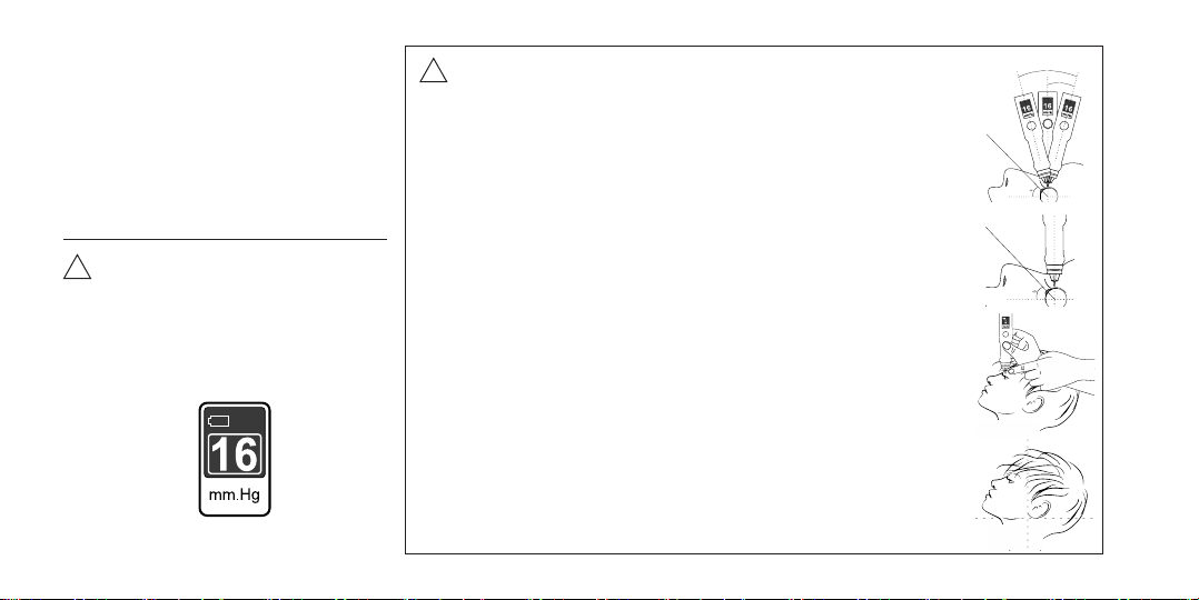
!Attention! An exclamation point symbol displayed in the
Tonometer window, accompanied by continuous beeping
sound, is a signal of its inoperable condition and of
excessive pressure load of the rod upon the eyelid, which
may cause painful sensations for a patient.
!Precaution!
The Tonometer should not be used on eyes with
biomechanical properties altered by prior surgery or
disease.
3
Schematic
representation
of the Tonometer rod
movements
1. DESCRIPTION AND DESIGN FEATURES.
OPERATING PRINCIPLE
When placing the Tonometer rod on the
eyelid and applying light pressure to the
device, the rod is slightly immersed in-
side the device and the formaon of a
measuring vibraonal effect begins.
The vibraon frequency of the «rod-
eye» ligament depends on the IOP.
The higher the IOP, the greater the fre-
quency of vibraons.
The Tonometer registers the vibraon
frequency, recalculates it into the IOP
value and displays it on its indicator.
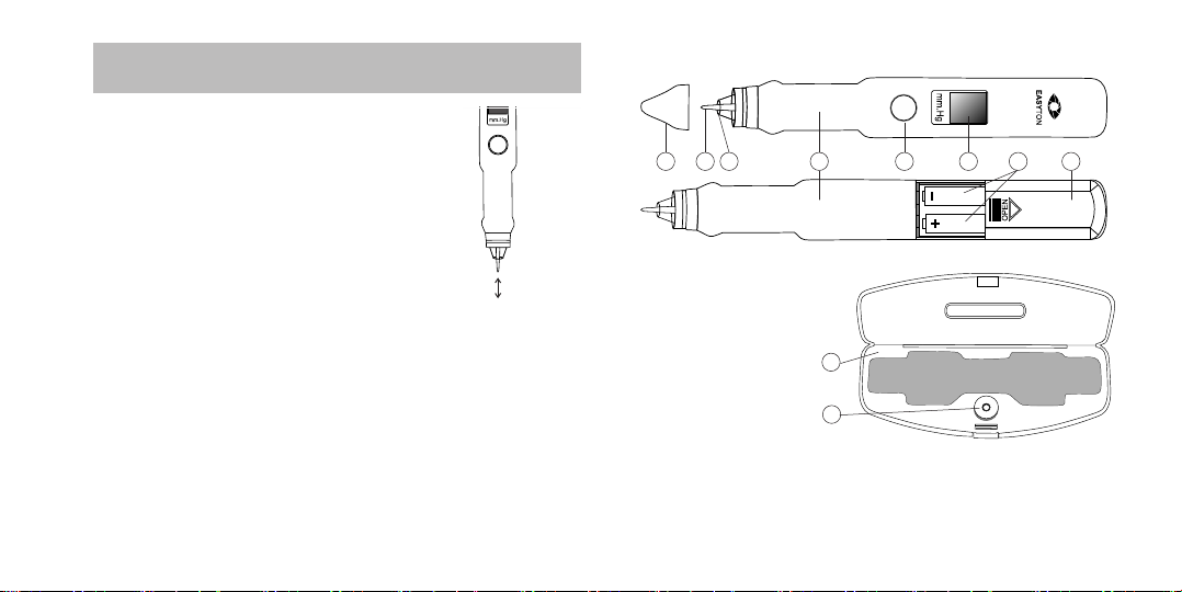
Key Design Features
A. Tonometer body
B. On/Offbuon
C. Display window
D. Vibrator rod
E. Buffer ring
F. Protecve cap
G. Baery case cover
H. Baeries
I. Case box
J. Tester
F D E A B C H G
I
J
Figure 1
Figure 2

4
Display Symbols
K. Baery level indicaon
L. Ready-for-operaon indicaon
M. Measured IOP reading
N. Square frame around the reading value = unstable posioning
of the Tonometer, or the paent’s eyelid or eye
O. IOP value below the measurement range (below 7 mmHg)
P. IOP value above the measurement range (above 50 mmHg)
L M N
K K K
Complete Set
• EASYTON Tonometer 1
• Built-in tester case 1
• 1.5 V battery standard size ААА, R03 2
• Operang Manual 1
• Retail packaging 1
Important Facts on Intraocular Pressure
Intraocular pressure measurement is a method of
eye health diagnostics used in ophthalmology.
Intraocular pressure generally has 3 basic condi-
tions:
• normal
• hypertension (high pressure)
• hypotension (hypotony)
Stascally, the normal range of true IOP (Р0) is
within 10 to 21 mmHg. IOP may be irregular or
may change in the course of the day. The normal
value may vary in the range of 2-2.5 mmHg.
O
K
P
K
Figure 3

5
2. PREPARATION FOR OPERATION
2.1. Battery Installation and Replacement
The current baery status is marked with the power level indica-
tor in the top lecorner of the Tonometer display.
Baeries fully
charged
Baeries parally
discharged
Low baery
If the baƩeries are discharged, the Tonometer will not switch on.
Batteries are to be replaced with the Tonometer switched off.
If you plan to use the device again only in a few months’ Ɵme,
make sure to take the baƩeries out.
Turn the Tonometer over so
that its front panel is facing
downwards.
Slide the battery case cover
in the direction of the arrow
marked on it.
Insert / replace the two AAA
batteries in such a way so
that their «+» (positive) and
«–» (negative) contacts would
match the polarities marked
inside the battery case.
Put the battery case cover
back on.
press your finger
against the housing
slide the cover in
as far as it can go
Attention! Immediately after inserting
the batteries, switch the Tonometer
on and offby shortly pressing the On/
Offbutton.
This is done to check proper installation
of the batteries, and the Tonometer is
set into the micro-consumption mode.
!
1
2
3
4
Figure 4
Figure 5
6
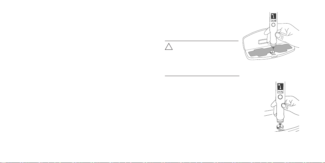
Position the Tonometer
vertically above the tester.
The heel of the hand holding
the device should rest against
the table surface.
Keeping the heel of the hand fixed
on the table, insert the device rod
down into the center of the tester
pinhole. Dip the Tonometer buffer
ring as far down as it can go into the
circular groove of the tester. The lower
surface of the Tonometer ring should
be aligned with the circular groove
surface as much as possible.
At this point, the measuring mode is
actuated, which is perceived by the
hand as light vibration. Meanwhile,
the pressure value is displayed in the
Tonometer window.
2.2. Functionality Checkup Using the Tester
The Tonometer funconality is to be checked on the tester at
least once a week, as well as in the following cases:
• aer long idle periods
• aer dropping the device
• aer changing the baeries
• in any other cases when you doubt if the Tonometer
works properly
To check the Tonometer functionality on the tester, do as
follows:
Open the Tonometer case.
Take the device out and put the opened case with the
tester on a table.
Position the Tonometer with the rod up and take the
protective cap off.
Shortly press the On/Offbutton to switch the
Tonometer on.
A moving arrow displayed in the Tonometer window
indicates its readiness for operation.
Hold the Tonometer with your fingers by the cylinder-
shaped part of its housing.
Place the Tonometer with the measuring rod down and
position its housing so as to be able to see the readings
on the display.
Attention! Upright positioning
of the Tonometer (allowed
deviation from vertical axis
should not exceed 15 degrees)
must be preserved during all
measurements.
!
ready-for-
operaon
1
2
3
4
5
6
7
8
9
Figure 6
Figure 7

7
measurement
mode
measurement
completed
Keeping the device fixed in this
position, keep an eye on the
digital value of the pressure
displayed in the Tonometer
window. The measuring mode will
continue until the device is lifted
away from the tester. The digital
reading on the display should not
diverge from the one listed in the
«Specifications» section of this
Manual by more than two units.
Raise the Tonometer above the
tester. The measuring mode
is thus completed, and the
measured value is captured on the
display.
The measuring can be repeated
for as many times as needed,
following Clauses 9, 10, and 11 of
this section.
Deactivate the Tonometer by
shortly pressing the On/Off
button.
Put on the protective cap, with the
Tonometer rod turned upwards,
and put the device into its case.
10
11
12
13
14
2.3. Disinfection
Please disinfect the Tonometer while it is switched off.
Disinfecon of the buffer ring and Tonometer rod should be performed
before and aer each new paent’s IOP measurement.
To perform the disinfecon procedure, do as follows:
Pour use the Rapicide PA disinfeccting solution into tray.
Holding the Tonometer with the rod down, treat the buffer
ring and the lower part of the rod immerse in solution for at
least 15 minutes.
Attention! Only the working parts of the Tonometer need to be
immersed, at a distance not exceeding 1 cm from the edge of the
ring (see Figure 10).
!
Remove disinfected the Tonometer from the
tray using aseptic procedure and rinse them
in sterile water.
Thoroughly rinse the buffer ring and the
lower part of the rod by immersing it in a
large volume of water and keep it immersed
for a minimum of 1 minute.
Manually flush the buffer ring and the lower
part of the rod with large volumes of rinse
water. Avoid penetration of moisture inside the Tomometer.
1
2
3
4
5Figure 10
Figure 8
Figure 9
8
Disinfection of the outer surfaces of the Tonometer body
(others than the rod and the buffer ring) is performed as
may be needed, using 3% hydrogen peroxide solution mixed
with 0.5% solution of a household detergent.
After disinfection, wipe the outer surfaces of the display
with a dry sterile cloth.
The process of disinfection of the tonometer was validated
and was recognized as acceptable by the results of tests in
the mycobiological laboratory.
Attention! Avoid penetration of the disinfectant solution
inside the Tonometer.
!
3. DEVICE APPLICATION PROCEDURE
3.1. Pre-Measurement Steps
1
2
3
4
5
3.2. Measuring Procedure
•
•
•
•
Hold the activated
Tonometer with your fingers
by the cylinder-shaped part
of its housing.
Place the device with its rod
facing downwards. Turn the
Tonometer so as to be able to
see the readings on the display.
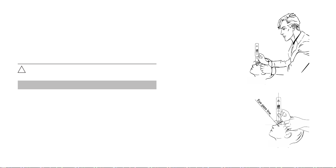
Stand at the patient’s side
slightly behind them.
The patient’s gaze must be fixed
at a test object (for instance,
their own hand), heir eye gaze
line making up an angle of 45°
from upright direction.
Take the Tonometer out of its case.
Position the Tonometer with the rod up and take the
protective cap off.
Disinfect the Tonometer (see Cl. 2.3).
Shortly press the On/Offbutton to switch the
Tonometer on. When activated, the Tonometer
produces a beeping sound.
Check for presence of a moving arrow on the Tonometer
display, which indicates its readiness for measuring.
Check the Tonometer functionality using
the tester (see Cl. 2.2).
Before measuring, the patient should
be in a sitting position with his
head tilted back so that the
position of the head was as
close to horizontal as possible.
6
7
Figure 11
Figure 12

9
•The vertical position of the
instrument rod on the surface of the
eye is an essential condition for the
accuracy of IOP measurement. Place
the Tonometer rod on the upper
eyelid of the patient 2-3 mm from its
edge (in the sclera region), holding
the tonometer body strictly vercally.
The contact area of the tonometer
rod should fall on the upper por-
on of the sclera corresponding to
corona ciliaris in Meridian 12 (Figure No 14). Recom-
mended installaon points are indicated in the figure.
Attention! Avoid slipping of the eyelid onto the cornea
while taking the measurement!
!
•
•
The heel of the hand holding the Tonometer should rest
against the patient’s forehead. The smoothness and
preciseness of movements required for the measuring
process is achieved by resting the hand against the
patient’s head (forehead), as well as trained through
continuous usage.
Stretch the upper eyelid with a finger of your free hand
in a way to ensure alignment of the upper eyelid edge
with the upper corneal edge. Fixate and hold the eyelid
in this position, without pressing on the eyeball.
• Holding the Tonometer vertically
down, smoothly lower it down
by 2-3 mm. At this point, dynamic
force is actuated, which is
perceived as light vibration.
During the measuring process,
make sure that the buffer ring does not touch the
eyelid, but remains 2-3 mm above the eyelid surface.
Avoid slipping of the eyelid onto
the cornea while taking the
measurement.
Attention! When the Tonometer is
lowered too far down, it produces a
continuous single-tone beep, which
stops automatically when the device
is raised high enough for measuring.
!
•1 or 2 seconds after lowering the Tonometer down, it
produces a beep indicating that the measurement is
completed, and the measured IOP value is displayed in
its window. The measuring process will continue until
the device is lifted away.
To end the process, lift the device up. At the moment
when the measurement is taken, the device produces
another beep, and the measured IOP value is displayed
in the window.
Figure 13
Figure 14
Figure 15
10
Attention! If the positioning of the
Tonometer, the patient’s eyelid
or eye, is unstable during the
measuring process, the resulting
reading may appear on the display in
a square frame. If this happens, the
measurement needs to be re-taken.
!
•
•
In case if the sound signal didn’t
come offat all or came offwith a
delay of more than 3 seconds, the
measuring needs to be repeated.
Deactivate the Tonometer by
shortly pressing the On/Offbutton.
Put the protective cap back on,
with the Tonometer rod up, and
put the device back into its case.
Attention! To obtain the most accurate IOP
measurement results, the following conditions
must be observed:
!
•The Tonometer body should be posioned strictly
upright.
When measuring, try to hold the tonometer body
strictly upright, avoiding its deviaon by more than 15
degrees.
•The Tonometer rod should be posioned at right
angle against the eye surface.
To achieve that, align the Tonometer rod axis with the
geometric center of the eyeball.
•Smoothness and preciseness of movements during
the measuring process.
These can easily be achieved when the hand holding
the Tonometer is resng against the paent’s head
(forehead).
•The paent's posion at the me of measurement.
At the me of the measurement, the paent should
be in a sing posion with his head lted back so that
the posion of the head is as close to horizontal as
possible.
15о
30о
Figure 16
Figure 17
Figure 18
Figure 19
Figure 20

11
4. POSSIBLE ERRORS AND TROUBLESHOOTING
Problem Possible cause Troubleshooting method
The Tonometer does not switch on The batteries are dead Replace the batteries
The batteries are seated
incorrectly
Insert the batteries with due regard to the
polarity markings (+ / -)
The contact of the batteries is
unstable
Replace the batteries. Clear the contacts of the
battery holders using an erasing rubber
The On/Off button is broken Repair at a maintenance service facility
The Tonometer itself is broken Repair at a maintenance service facility
The Tonometer readings obtained with the tester
deviate from the values specified in the Manual by
more than 2 units
The Tonometer is de-calibrated Calibration at a maintenance service facility
The Tonometer is broken Repair at a maintenance service facility
After the measurement is completed (and the
Tonometer lifted up), the vibration action does not
stop or stops only after a notable delay (more than a
second)
The rod motion sensor is de-
calibrated
Calibration at a maintenance service facility
When switching the Tonometer on, it does not display
any indications, and an alarm signal is produced
The Tonometer display is broken Repair at a maintenance service facility
The batteries run low too soon (in less than 30 days) Excessive power consumption Repair at a maintenance service facility

12
5. MAINTENANCE SERVICE AND MINOR REPAIRS
Maintenance Procedure
Procedure Frequency
1. Routine inspection At least once a day
2. Cleaning from dust and dirt As may be necessary
3. Functionality checkup Before each IOP
measurement procedure
4. Battery changing When the symbol « »
appears on the display
Minor Repairs
During routine inspection, make
sure to check the integrity of the
Tonometer body and to check
for mechanical damages of the
vibrator rod.
The Tonometer functionality
checkup is to be done as
described in the clause titled
«Tonometer Functionality
Checkup Using the Tester».
Do not attempt any
repairs by yourselves.
Should you have any
doubts regarding
correct operation of the
device, please contact
the Manufacturer or its
representative office.
!
Minor repairs of the Tonometer are provided by the
Manufacturer or its representative facility, after a technical
inspection of the malfunction nature and degree has been
performed by the Manufacturer’s experts.
The following may indicate presence of a malfunction:
•mechanical damages of the Tonometer housing and
(or) vibrator rod;
•divergence of the Tonometer readings obtained with
the tester from the ones listed in the «Specifications»
section;
•absence of readings on the display despite presence of
the sound of the rod vibration specific for measuring;
•absence of the power level indication symbols.
During minor repairs, troubleshooting is done by
replacement or recovery of the parts and elements;
adjustment of the Tonometer is conducted to ensure its
compliance with the parameters listed in this Manual. Upon
completion of the repairs, the Tonometer is returned to the
user, and its warranty period is renewed starting from the
date of return.
Safety Measures
No special precautions are required while conducting the
repairs.

13
6. SPECIFICATIONS
Parameter Parameter value
Device Transpalpebral digital tonometer for
intraocular pressure measurement
Model EASYTON
IOP readings range, mmHg 7-50
Accuracy, mmHg, within the range of:
7-23 mmHg ±2
above 23 mmHg ±5
Repeatability (coefficient of variation), % ≤8,1
Accuracy of display, mmHg 1
Display unit Millimeter of mercury (mmHg)
IOP measurement time, sec, max 2
Power consumption during
measurement, mA, max 100
Power supply: No. of elements and voltage 2 × 1.5V, standard size ААА, R03
Display LCD
Data output Display window
Overall dimensions (L×H×W) mm, max 173 × 27 × 21
Weight, g, max 88, incl. batteries
Operating conditions:
operating temperatures range, °Сfrom +10 to +35
relative air humidity,%, max 80
atmospheric pressure, mmHg 630-800
Mean service life, no less than 5 years
7. STORAGE AND TRANSPORTATION
The Tonometer may
be stored in a closed
non-heated room at a
temperature from
-50 °Сto +40 °Сand
relative air humidity
of up to 98% (at a
temperature of + 25 °С).
The device can be
transported by all
covered vehicles in
microclimatic regions
with a moderately cold
climate at ambient air
temperatures from -50 °С
to +50 °С.
Attention! After a long storage or transportation
at temperatures below +10 °C, keep the
Tonometer in a room at a temperature from +10
to +35 °C for at least 4 hours.
!
Tonometer readings obtained with the tester in the
IOP measurement ________________ ±2 mmHg.
(to be filled in at device acceptance)

14
8. MARKING
The Tonometer is marked with the following symbols:
Refer to the operang manual
The Tonometer’s working part is the
sufficiently protected against electric shock
The product is licensed with Approval
Cerficate of Measuring Instruments
Compliant with CU TR 020/2011 Technical
Regulaons of the Customs Union
Compliant with MDD 93/42/ЕЕС
Safety and effectiveness of the tonometer in the intended
environment of use is supported by testing that was
conducted in accordance with the following standards:
ISO 10993-1 «Medical products. Assessment of medical
products biological effect. Part 1. Assessment and investigation»
ISO 10993-9 Biological evaluation of medical devices – Part 9:
Framework for identification and quantification of potential
degradation products
ISO 10993-10 Biological evaluation of medical devices – Part 10:
Tests for irritation and skin sensitization
ISO 10993-11 Biological evaluation of medical devices – Part 11:
Tests for systemic toxicity
ISO 10993-12 Biological evaluation of medical devices – Part 12:
Sample preparation and reference materials
ISO 15223-1:2016 Medical Devices – Symbols To Be Used
With Medical Device Labels, Labelling, And Information To Be
Supplied – Part 1: General Requirements
IEC 60601-1-2:2014 (4th edition) Medical electrical equipment
– Part 1-2: General requirements for basic safety and
essential performance – Collateral standard: Electromagnetic
compatibility – Requirements and tests
IEC 61000-4-2:2012 Electromagnetic compatibility (EMC) –
Part 4-2: Testing and measurement techniques – Electrostatic
discharge immunity test

15
IEC 61000-4-3:2006+AMD1:2007+AMD2:2010 Electromagnetic
compatibility (EMC) – Part 4-3: Testing and measurement
techniques – Radiated, radio-frequency, electromagnetic field
immunity test
IEC 61000-4-8:2009 Electromagnetic compatibility (EMC) – Part
4-8: Testing and measurement techniques – Power frequency
magnetic field immunity test
CISPR 11:2009 +A1:2010 Industrial, scientific and medical
equipment – Radio-frequency disturbance characteristics –
Limits and methods of measurement
DIN EN ISO 15223-1:2013 Medical devices – Symbols to be
used with medical device labels, labelling and information to be
supplied – Part 1: General requirements (ISO 15223-1:2012)
ANSI Z80.I0-2014 Ophthalmic instruments. Tonometers
During pre-market testing process the comparability testing
to a Goldman type reference tonometer was performed on
eyes in according to ANSI Z80.10-2014 and satisfied results
was reached. The resulting Pearson correlation coefficient
is more 95% (see pictures below). This indicates the high
accuracy of the EASYTON tonometer compared to the
Goldman tonometer. As a result of the tests, the required
accuracy and repeatability of the measurements were
confirmed.
mmHg
mmHg
mmHg
mmHg

16
9. MANUFACTURER’S WARRANTY
The Manufacturer hereby guarantees that the quality of
the Tonometer conforms to the requirements stated in the
Operating Manual, provided that the conditions of proper
storage, transportation, and usage are met by the Customer.
Guaranteed service life (warranty period) is 24 months from
the date of sale.
Within the warranty period, the Manufacturer shall repair
or replace the defective Tonometer free of charge, upon
presentation of the warranty service coupon.
Warranty provisions
The warranty is only valid if the Customer has a correctly filled-
in warranty coupon, with the factory serial number and date of
sale indicated, and a vivid stamp of the trading company.
The warranty does not cover the following cases:
•if the Tonometer bears traces of outside interference
or repair attempts by non-authorized servicing
companies;
•if unauthorized changes into the design or construction
of the Tonometer have been detected;
•if the Tonometer has any mechanical damages;
•if the Tonometer has been damaged as a result of
penetration of foreign objects, substances or liquids.
The batteries are not covered by this warranty.
When the service life or operational life cycle of the
batteries expires, the Customer is to replace them of their
own accord.
The guaranteed shelf life is 24 months.
Please send a faulty Tonometer for repairs, together with
the Operating Manual and an enclosed explanatory note, to
the Manufacturer’s representative at the following address:
For any quesons on the device quality and maintenance service,
please contact the Manufacturer’s representave.

17
10. ACCEPTANCE CERTIFICATE
EASYTON transpalpebral digital tonometer for intraocular
pressure measurement factory serial number
is manufactured and accepted in compliance with the
technical specification GIKS.941329.102 TS and is hereby
validated as ready-for-service.
Software version No. GIKS.17-0104.3.
Date of producon Stamp
EASYTON transpalpebral digital tonometer for intraocular
pressure measurement is packed according to the require-
ments specified in the design documentaon.
Date of packing
Packed by Stamp
(signature of a person responsible for acceptance)
Manufacturer's manual and declaration – electromagnetic emission
The tonometer is intended for use in the electromagnec environment spec-
ified below. The purchaser of the tonometer should ensure its use in the
specified electromagnec environment
Electromagnetic
emissions test
Compliance Electromagnetic environment –
instructions
Radio-interferences
according to CISPR 11
Group 1 The tonometer uses radio-frequen-
cy energy only to perform internal
funcons. The emission level of the
radio frequency interference is low
and might not lead to disturbances
in the funconing of the electronic
equipment located close to it
Radio-interferences
according to CISPR 11
A Classes The tonometer is suitable for use
in all the locaons, not used for do-
mesc purposes and not connected
to low-voltage distribuon networks
The harmonic current
components
of IEC 61000-3-2
Not applied
11. APPENDIX A
Table 1

18
Manufacturer’s manual and declaration – interference resistance
The tonometer is intended for use in the electromagnec environment specified below. The purchaser or user of the tonometer should ensure its use in the specified
electromagnec environment.
Interference resistance test The test level according to IEC 60601 Compliance level Electromagnetic environment – instructions
Electrostac discharge (ESD)
according to IEC 61000-4-2
±8 kV – contact discharge
±2,4,8,15 kV – air discharge
Complies The floor in the facility must be covered with wood, concrete
or ceramic tiles. If the floor is covered with synthetic material,
relative humidity must be minimum 30%
Electrical fast transient/burst
according to IEC 61000-4-4
±2 kV – for powersupply lines
±1 kV – for input-output lines
Not applied Power quality in mains in accordance with the typical
conditions of a commercial or hospital environment
High energy
microsecond pulse interferences
according to IEC 61000-4-5
±2 kV Not applied Power quality in mains must be provided in accordance
with the typical conditions of the commercial or hospital
environment
Voltage dips, average interrup-
ons and voltage fluctuaons
in the input power lines
according to IEC 61000-4-11
- UH=0%, 0,5 cycle
(0,45,90,135,180,225,270 and 315 dagrees
- UH=0%, 1 cycle
- UH=70%; 25/30 cycles (0 dagrees)
- UH=0%, 250/300 cycle
Not applied Power quality in mains in accordance with the typical
conditions of a commercial or hospital environment If the
user of the device needs to provide seamless operation in the
conditions of possible interruptions of the line voltage, it is
recommended to power the device from an uninterruptive
power supply or battery
Power frequency magnec field
(50/60 Hz) according
to IEC 61000-4-8
30 A/m Complies The levels of power frequency magnetic field must be provided
in accordance with the typical conditions of the commercial or
hospital environment
Note: UH– is the voltage level of the mains unl test exposure is applied
Table 2
19
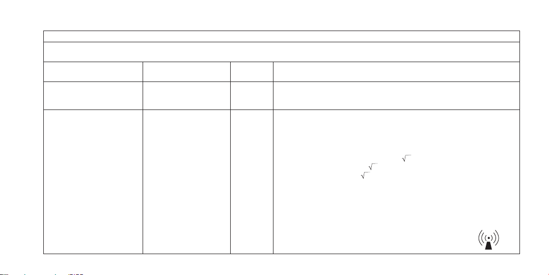
Manufacturer’s manual and declaration – interference resistance
The tonometer is intended for use in the electromagnec environment specified below. The customer or the user of the tonometer should ensure its use in the
specified electromagnec environment.
Interference resistance test The test level
according to IEC 60601
Compliance
level
Electromagnetic environment – instructions
Conducted disturbances
induced by RF fields according
to IEC 61000-4-6
3 V (root-mean-square)
in-band from 150 kHz to
80 MHz
Not applied Evaluaon of the effecveness of the effect on conducted interference induced by
radio-frequency electromagnec fields
Radio-frequency electromag-
nec field according
to IEC 61000-4-3
3 V/m in-band from 80 MHz
to 2.7 GHz
Complies The distance between the mobile radiotelephone communicaon systems used and
any element of the tonometer, including the cables, should not be less than the
recommended separaon distance which is calculated in accordance with the ex-
pressions below with reference to the frequency of the transmier.
Recommended separation distance:
d = 1,2 P
d = 1,2 P (from 80 to 800 MHz);
d = 2,3 P (from 800 MHz to 2.7 GHz).
Where d is the recommended separation distance, m b);
P is the nominal maximum transmitter output power, W, as specified by the
manufacturer.
The field density in the propagation of radio waves from stationary radio transmitters,
according to the results of observations of the electromagnetic situation a), should
be lower than the level of correspondence in each frequency band b). The effect of
interference may occur near the equipment marked with the symbol
Table 3
Other manuals for EASYTON
1
Table of contents
Other Elamed Measuring Instrument manuals

Popular Measuring Instrument manuals by other brands

Hioki
Hioki TM6102 instruction manual

Sanwa
Sanwa YX-361TR instruction manual

LaserLiner
LaserLiner MasterCross-Laser 2GP operating instructions

ATD Tools
ATD Tools ATD-3696 instructions

HB Products
HB Products HBSC2 Instruction manual supplement

SW Stahl PROFI Tools
SW Stahl PROFI Tools S3531 instruction manual


