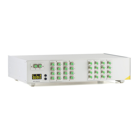
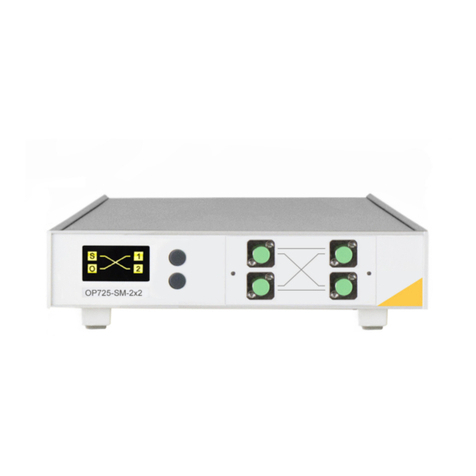
OptoTest OP720 User manual

Multichannel Optical Switch
Instruction Manual
OP720
www.optotest.com 1.805.987.1700

1 of 7
Contacting OptoTest Corporation
1.805.987.1700 (7:30 a.m. to 5 p.m. PST)
www.optotest.com
OptoTest Corp.
4750 Calle Quetzal
Camarillo, CA 93012 USA
Notice of Proprietary Rights
The design concepts and engineering details embodied in this manual, which are the
property of OptoTest Corporation, are to be maintained in strict condence. No element
or detail of this manual is to be spuriously used or disclosed without the express written
permission of OptoTest Corporation. All rights are reserved. No part of this publication
may be reproduced, stored in a retrieval system, or transmitted in any form or by any
means, electronic, mechanical, photocopying, recording, or otherwise, without prior
written permission from OptoTest Corporation.
COPYRIGHT © 2016 by OptoTest Corp
ALL RIGHTS RESERVED
PRINTED IN THE UNITED STATES OF AMERICA
MnOP720-RevD

OP720
2 of 7
Table of Contents
Overview 3
Features 3
Initial Preparation 4
Front Panel Operation & Display 5
Multichannel Conguration 5
Bidirectional Conguration 6
USB Control of the OP720 7
Warranty Information 7

OP720
3 of 7
Overview
The OP720 is an optical switch for single mode or multimode applications available in
a slim-line, ultra-compact frame. This optical switch is USB powered and incorporates
the latest technology in high-speed switching. With high repeatability and low loss,
the OP720 is ideally suited for high channel count optical devices such as DWDM,
waveguides, and splitters.
Features
• Compact, slim-line, ultra thin all optical switch
• MEMS technology, high reliability, long life
• USB powered, no external power supply needed
• Bright organic OLED for channel display
• Interface to custom applications via OPL-SDK
• High speed USB Interface for communication
• 2x2 conguration available for bi-directional testing

OP720
4 of 7
Initial Preparation
Unpacking and Inspection
The unit was carefully inspected, mechanically, electrically and optically before shipment.
When received, the shipping carton should contain the items listed in Standard
Contents. Account for and inspect each item. In the event of a damaged instrument,
write or call OptoTest Corp, California.
Note: Be aware that accessories such as detector adapters, remote head detectors,
and high performance reference cables will be located inside a small box labeled
“Accessories Inside”. If this box is not included with the original shipment, contact
OptoTest of their nearest distributor.
Please retain the shipping container in case re-shipment is required for any reason.
Damaged In Shipment
All instruments are shipped F.O.B. Camarillo when ordered from OptoTest.
If you receive a damaged instrument you should:
1. Report the damage to your shipper immediately.
2. Inform OptoTest Corporation.
3. Save all shipping cartons.
Failure to follow this procedure may aect your claim for compensation.
Standard Contents
1. Model OP720 Multichannel Optical Switch
2. Power Cord (U.S. Shipments only)
3. USB A-B cable
4. Certicate of Calibration and if requested the Metrology Report
5. Instruction Manual(s)
6. CD with applicable software and documentation (if ordered)
7. Rack mount kit (optional)

OP720
5 of 7
Front Panel Operation & Display
Multichannel Configuration
Channel Selection
By pressing the top button the instrument display switches to the next channel, it will
loop at the last channel to the first channel. Similarly the bottom button switches the
instrument to the previous channel.
Some systems may have other push button features. In this case, the left and right
arrow buttons indicate previous and next channel. Also the two push buttons above the
left and right arrow buttons switch between rows. For example, for a 48-channel system
set to Channel 1 would move to channel 13 if the “next row” push button was pressed.
Similarly, if the “previous row” push button was pressed, it will move to Channel 37.
Channel Display
Shows the current selected channel.
Current
Channel
Next
Channel
Previous
Channel

OP720
6 of 7
Front Panel Operation & Display
Bidirectional Configuration
Mode Selection
Both push buttons allow the user to toggle between crossed mode or bar mode.
Bar Mode: This option is used for forward unidirectional testing. At this mode, the
Source port is connected to port 1, which outputs to port 2 and then to the OPM port.
Crossed Mode: Switching to crossed mode allows for testing in the reverse direction of
the cable without flopping. At this mode, the Source port reroutes to port 2 and outputs
to port 1, then eventually to the OPM port.
Channel Display
The display shows graphically the current mode of the unit.
S
O
1
2
Current Mode
Bar Mode
Current Mode
Crossed Mode
Toggle
Mode
Toggle
Mode
Toggle
Mode Toggle
Mode
S
O
1
2

OP720
7 of 7
USB Control of the OP720
The OP720 can be controlled via the USB bus. Upon request, OptoTest can supply
the appropriate DLLs along with sample programs to facilitate the software creation
process. For these DLLs please contact [email protected].
Warranty Information
OptoTest Corp. warrants this product to be free from defects in material and
workmanship for a period of one year from date of shipment. During the warranty period
we will, at our option, either repair or replace any product that proves to be defective. To
exercise this warranty contact OptoTest Corp. Headquarters. You will be given prompt
assistance and return instructions. Repairs will be made and the instrument returned,
transportation prepaid. Repaired products are warranted for the balance of the original
warranty period, or at least 90 days.
NOTE: Do not send instruments for any reason without contacting OptoTest
headquarters first.

For Application Notes, more detailed Testing
Instructions, and the most up-to-date OptoTest
News go to www.optobuzz.com

www.optotest.com
1.805.987.1700
Table of contents
Other OptoTest Switch manuals