Resideo Technologies, Inc.
2 Corporate Center Drive, Suite 100
P.O. Box 9040
Melville, NY 11747
1-800-645-7492
For more information
resideo.com L/5869TRAND/D | 02/20
© 2020 Resideo Technologies, Inc. AIR SECURITY WATER ENERGY
5869 Technical Specifications
ORDERING
5869 Holdup Switch/Transmitter
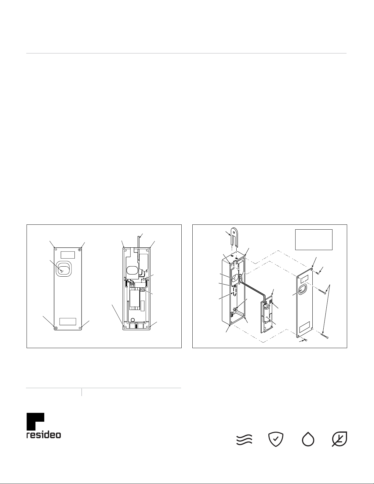
INSTALLATION
Mount the 5869 under a counter or money
drawer for easy access by the cashier.
Refer to the steps and figures that follow
for typical mounting instructions.
Before mounting the 5869 permanently,
perform Go/No Go tests to verify
adequate transmitter signal strength
at desired mounting location (refer
to the Security System Control Panel
Installation and Setup Guide).
1. Remove the two screws (Figure 1)
securing the cover to the 5869 case.
NOTE: The holes located in the opposite
corner, to the screws that secure the cover
to the case, provide a means for securing
the transmitter to the counter or drawer.
2. Using the case as a drill template,
position the case in the desired location.
3. Drill a 1/16-inch pilot hole at the
breakaway tamper release hole and the
two case mounting holes (Figure 2).
4. Attach the case to the counter
or money drawer using one No.
6 x 3/4 screw (supplied) at the
breakaway tamper release.
5. Install the battery (see BATTERY
INSTALLATION/REPLACEMENT).
6. Secure the cover to the case with the
two screws removed in step 1.
7. Secure the assembled case to the
counter or drawer using the two No. 6 x
2 mounting screws supplied (Figure 2).
PROGRAMMING
The 5869 Holdup Switch/Transmitter
should be programmed as a 24-hour silent
zone type. Refer to the Security System
Control Panel Installation and Setup
Guide for programming instructions.
NOTES:
• During programming of the control panel,
the 5869 Holdup Switch/Transmitter
should be treated as “RF” (i.e., supervised
RF) Type.
• The 5869 is one closed input loop zone
(loop 1).
BATTERY INSTALLATION/REPLACEMENT
1. Remove and retain screws
securing the 5869 cover.
2. Observing correct polarity, insert
the battery into the battery holder.
NOTE:Use care not to bend the antenna
while attempting to install battery.
3. Re-install screws to secure cover and/
or assembly. Refer to Figure 1.
HOLDUP
TRANSMITTER
DEVICE
HOLE
SCREW
TRIGGER
HOLE
COVER
+
5869-002-V0
+
MOUNTING
HOLE
TRIGGER
HOLE
TRIGGER
BREAKAWAY
TAMPER
RELEASE
RESET
KEY
COVER
TAMPER
RELEASE
SWITCH
MOUNTING
HOLE
COVER
SCREW (2)
No. 6X1/2
COVER
3V
LITHIUM
BATTERY
CIRCUIT
BOARD
COVER
AT TA CH HOLE
COVER
AT TA CH
HOLE
MOUNTING
SCREW (2)
No. 6X2
BREAKAWAY
TAMPER
RELEASE
SCREW HOLE
INDEX
TA B
+
COVER
SCREW
NOTE
CIRCUIT BOARD REMOVED
FOR CLARITY ONLY. DO NOT
REMOVE CIRCUIT BOARD
DURING INSTALLATION.
MOUNTING
HOLE
COVER
AT TA CH
HOLE
INSIDE VIEW
WITH
KEY
COVER TAMPER
3V
LITHIUM
BATTERY
+
MOUNTING
HOLE
VER
TACH
HOLE
BREAKAWAY
TAMPER
RELEASE TA B
SCREW
HOLE
FIGURE 1 FIGURE 2


