Optus DHR 4901 OPT User manual

Optus Satellite
Set-top box
Generation 2
User Guide
DHR 4901 OPT
Satellite
.

Contents
1 Warranty and safety / warnings 3
2 Welcome 6
3 Main features 7
4 What’s in the box 8
5 Hardware 9
5.1 Front panel 9
5.2 Rear panel 10
5.3 Remote control unit RCU) 11
6 How to connect your set top box 14
6.1 Quick start guide for existing installations 14
6.2 Quick start guide for new installations 14
6.3 Additional information 16
7 First time start- up of the set top box 17
8 General functions 20
9 Main menu screen 24
9.1 TV portal 25
9.2 Timers 25
9.3 Record 27
9.4 Electronic program guide (EPG) 27
9.5 Media 34
9.6 Settings 35
10 Troubleshooting 44
11 Legal matters 45
The DHR 4901 OPT Basic Viewer’s Guide is the subject of intellectual
property rights, including copyright, under domestic law and
international conventions.
All rights are reserved. The DHR 4901 OPT Basic Viewer’s Guide
supplements the information supplied with the packaging of the
Set Top Box as well as the detailed information available on our website.
Due to software upgrades, the features and functionalities in this Basic
Viewer’s Guide may differ from those on your Set Top Box. Please visit
www.optus.com.au/support/satellite for the latest Viewer’s Guide.
Please Note: The Network Operator requires the use of a 10.7 GHz (10700)
LNB to receive all available TV services.
!
!

3
1 Warranty and
safety / warnings
This product has been manufactured to comply with all the relevant Australian safety
standards. Please read the following safety precautions and warnings carefully,
adhered to all safety and warnings notes.
Warranty
The Warranty period begins with the date of purchase of the product. As evidence
of the date of purchase please present the according document (sales check,
invoice, delivery note, or similar). Please keep these documents in a safe place, as our
guarantee service is based on the time of purchase and the warranty conditions.
If the product is faulty and requires repair please contact Optus.
This product carries the RCM – Logo and is compliant with AS/NZS 4417.2; Radio
communications (Low Interference Potential Devices) Class Licence 2015; and
Greenhouse and Energy Minimum Standards (Digital Television Set-top Boxes)
Determination 2012.
Mains Supply: 100-240V AC 50-60Hz
The power pack is supplied with this Set Top Box. It operates within the range
100-240 V AC 50-60 Hz mains supply only. Connect the power cable to the
Set Top Box before connecting the other end to the power outlet. Disconnect the
Set Top Box from the power outlet before connecting or disconnecting the
Set Top Box from any other equipment.
A well-regulated 12V DC supply is essential for this unit to operate efficiently;
contact Optus for the recommended DC regulators.
Overloading: Do not overload a wall outlet, extension cord or adapter as this may
result in electric fire or shock.
Liquid: Do not expose this product to liquid of any kind. In addition, do not place
objects filled with liquid on near the unit.
Cleaning: Disconnect the product from the wall outlet before cleaning.
Use a light damp cloth (no solvents) to dust the product.

4
Ventilation: Never cover the ventilation slots in this product as these slots allow for a
proper airflow through the unit. Covering them may result in the unit overheating and
may not function properly.
• Never stand the product on soft furnishings or carpets.
• Never stack electronic equipment on top of the product.
Attachments: Do not use any unsupported attachments, as these may be hazardous
or cause damage to the product.
Connection to the lnb or antenna: Disconnect the product from the mains outlet
before connecting or disconnecting the cable from the LNB or antenna. Failure to do
so can result in damage to the LNB or antenna.
Connection to the TV:Disconnect the product from the mains outlet before
connecting or disconnecting the cable from the TV. Failure to do so can result in
damage to the TV.
Location: To avoid exposing the unit to lightning, rain or sunshine, place the product
indoors.
• Never place the unit on or near a radiator or heat register.
• Do not block the openings with any object, and do not place the product on a bed,
sofa, rug, or other similar surface.
• If you place the product on a rack or a bookcase, ensure that there is adequate
space and ventilation and that you have followed the manufacturers mounting
instructions.
• Do not place the product on an unstable shelf, stand, tripod, bracket, or table
where it can fall off. A falling product can cause serious injury to a child or adult and
serious damage to the appliance.
Lightning, storm or not in use: Unplug the unit from the wall outlet and disconnect the
LNB or antenna during a thunderstorm or when left unattended and unused for long
periods. This will prevent damage to the unit due to lightning and power-surges.
Extraneous objects: Do not insert any type of object through the openings in the unit,
where they can touch dangerous voltage points, damage electronic components or
other parts of the unit.
Replacement of parts: Only an authorised service technician specified by the
manufacturer can perform the replacement of parts.

5
Warnings!
To avoid damaging the mains power cord and plug:
• Do not modify the unit’s power cord or plug in anyway.
• Do not bend or twist the power cord.
• Make sure to disconnect the power cord at the mains plug outlet when servicing or
away for long periods.
• Always keep heating appliances as far as possible from the mains power cord to
prevent the protective plastic cover from melting.
To avoid electrical shock:
• Never open the main body of the unit.
• Do not insert metal or inflammable material inside the product.
• Never touch the mains power plug with wet hands.
• Disconnect the mains power cord in case of lightning.
To avoid damaging the product:
• Do not use the product when it is faulty. If you continue to use the defective
product, serious damage may occur. Make sure to contact your authorised local
product distributor for repairs to the unit.
• Do not insert metal or alien substance into the smartcard slot.
• Ensure that the unit is placed near an accessible mains socket.
Correct Handling of Batteries:
• Never subject batteries to heat such as extreme sunlight, fire or anything similar.
• Batteries can contain toxic substances. Please keep batteries well out of reach from
children as they may put batteries into their mouth and/or swallow them.
• Leaking batteries can cause damage to the remote control. Extract the batteries
from the remote control when the Set Top Box is not in use for a long time.
• Batteries can contain toxic substances that can damage the environment.
Please make sure that you dispose of batteries in accordance with statutory law.
Never throw batteries in your regular household waste.
• Normal batteries may not be charged. Never heat or thrown normal and
rechargeable batteries into open fire (danger of explosion!).
Disposal
In any case, never dispose of your Set Top Box and the batteries in your
regular household waste.
Please contact Optus to arrange the return of your set top box.
Intended use
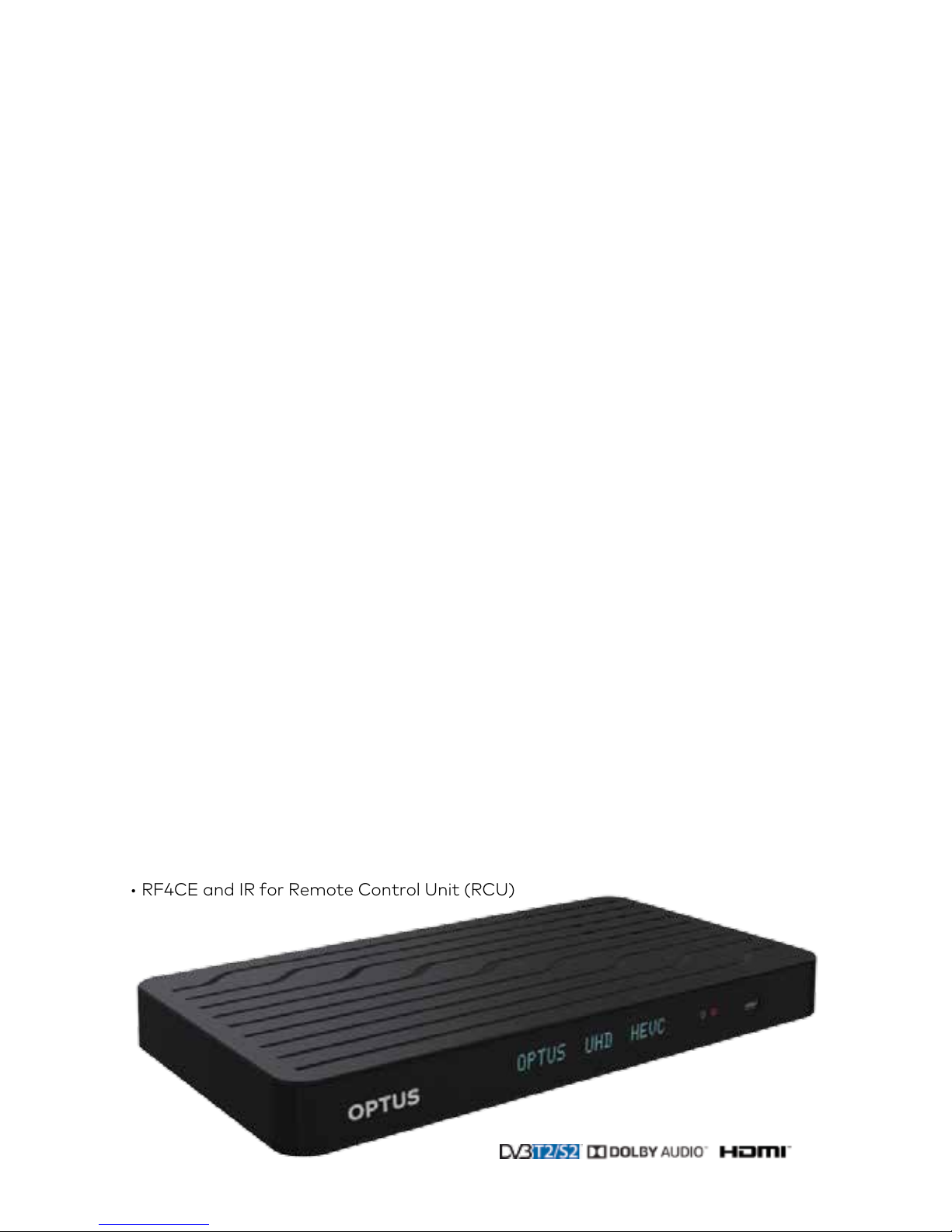
The purpose of this Set Top Box is for the reception of Digital Satellite and terrestrial
private use only.
• This involves also following all Information contained in this user manual, especially
the safety notes. Any other use is considered as not intended and can lead to
damage or even personal injury. This also implies immediate loss of warranty.
The manufacturer takes no liability for damages caused by unintended use.

6
2 Welcome
Welcome to the DHR 4901 OPT Optus Set Top Box designed for receiving digital
television services. This Set Top Box features Ultra High Definition (UHD), High
Definition (HD) and Standard Definition (SD) capabilities.
Please read and follow all the instructions in this User Manual before using one of the
various installation options provided in this manual, as well as becoming familiar with
the Front Panel and Remote Control Unit keys.
Identifying your Set Top Box
To identify the Set Top Box, look for a bar code sticker on the underside of your Set
Top Box or on the packaging which has a label attached displaying the product serial
number and the smart card number respectively.
Keep these numbers in a safe place, as your network provider requires them for
troubleshooting purposes.
Example: Bar code sticker on the
underside - base of your Set Top Box
Example: Gift box label

7
3 Main features
• Supports SD / HD (MPEG2, MPEG4, HEVC) /4k-UHD
• Conditional Access – Irdeto CA
• One smartcard Slot
• 16-Digit Vacuum Fluorescent Display
• Two USB 2.0 ports on rear
• One USB 2.0 port on front
• Ultra HD video output via the HDMI port
• Gigabit Ethernet port
• Wi-Fi (AC 2x2) – Future Support
• Internal 2TB HDD
• 16x DVB-S/S2 Satellite Tuners
• 4x DVB-T/T2 Terrestrial Tuners – Future Support
• Digital Audio Output on coax and optical
• On-Screen Display (OSD)
• On-Screen user installation assistance
• View Electronic Program Guide (EPG) “Now” and “Next” 7 days
• Parental control for all channels
• Recording functionality on Internal HDD. 1.5TB
• Records up to 10 simultaneous programs
• USB Multimedia for personal media playback – Future Support
• Multi-video output resolutions: 576i50 up to UHD 4K (2160p50)
• Various channel edit functions – Favourite Editing, Parental Lock Channel Rename,
Move and Delete etc.
• Software Upgrade support via OTA and USB
• RF4CE and IR for Remote Control Unit (RCU)
DHR 4901 OPT

8
4 What’s in the box
Check that all the following items displayed below are in the box and no damaged
occurred. If any items are missing or damaged, contact Optus.
1 x Set Top Box
1 x Remote Control Unit (RCU)
1 x 12V DC Power supply adapter
with power lead (PSU)
2 x 1.5V AAA Batteries
1 x User Manual
1 x HDMI Cable
1 x Optus Smart Card

9
5 Hardware
5.1 Front panel
1IR Receiver IR Receiver for the Remote control unit.
The Remote Control Unit (RCU) operates the receiver by sending a beam, which is
received by the infra-red window. Do not block the path between remote control
and this window.
2Front Panel Display
Vacuum Fluorescent
Display status
indicators
The following information could be displayed:
• Displays the time (when in Standby Mode)
• Displays the selected TV channel number being viewed.
• Displays any error code numbers when an error occurs.
3Standby Indicator RED / GREEN indicates if the Set Top Box is ON or in STANDBY mode.
4Record Indicator RED Record Indicator
5USB USB port provision for External Hard Drive / USB upgrade and/or future use
6Smart card The smart card slot is on the right hand side of the device. Insert a Smart card into
this slot for pay TV channels.
6Standby Button Switches the Set Top Box between ON and STANDBY

10
1ANTENNA IN VHF/
UHF
(future functionality)
Connects to the TV terrestrial antenna.
Connect the terrestrial antenna coaxial connector to the to the ANTENNA IN socket
on the Set Top Box.
2SAT IN Connects to the TV satellite antenna.
Connect the satellite antenna coaxial connector to the SAT IN socket on the
Set Top Box.
3DIGITAL AUDIO –
OPTICAL
Connects to the Digital Audio Optical (TOSLINK) input on your AV Home Theatre
System for Dolby Digital surround sound (if available in the program, and as
conigured in Setup).
4DIGITAL AUDIO –
COAXIAL
Connects to the Digital Audio Coaxial (SPDIF) input on your AV Home Theatre
System for Dolby Digital surround sound (if available in the program, and as
conigured in Setup).
5HDMI Connects to the high deinition (HDMI) input on TV or AV Home Theatre System.
Use the supplied HDMI cable to connect the HDMI output on the Set Top Box to
one of the HDMI inputs on the TV or AV Home Theatre System. Provides both high
deinition video, and Dolby Digital surround sound (when available).
6USB ports (2) USB port provision for External Hard Drive / USB upgrade and/or future use.
Connect to external equipment approved by your service provider i.e. external Hard
Disk Drive.
7LAN
(future functionality)
Ethernet port for internet connectivity.
Connect to external equipment approved by your service provider and to the Internet.
8DC POWER
12V ---5A MAX
12V DC input from the supplied power pack.
Connect the external power supply to the 12 V DC socket on the Set Top Box.
5.2 Rear panel

11
5.3 Remote control unit (RCU)
REMOTE CONTROL KEY BUTTON
NAME FUNCTION
1Standby Switches the set top box between ON
and STANDBY
Flashes red for IR mode, green for
RF mode
2PIP Picture in Picture. Allows for a second
viewing environment displayed in the
bottom right hand or the screen
3PVR Short cut key to all your recording
options
4TXT Functions as required by application
or context
5PORTAL Short cut key to launch Portal system
6SUBT Launches subtitles
7V O L+ Increases the volume
8CH+ Allows channel up navigation
9MUTE Turns the sound ON/OFF
10 VOL- Decreases the volume
11 CH- Allows channel down navigation
12 EPG Short cut key to launch Electronic
Program Guide (EPG)
13 MENU Short cut key to launch Menu system
14 INFO Display information about the current
program
15 Up Arrow Menu navigation and selection - Up
16 Left Arrow Menu navigation and selection - Left
17 OK Menu navigation and selection - OK
18 Right Arrow Menu navigation and selection
- Right
19 Down
Arrow
Menu navigation and selection
- Down
20 EXIT To exit from the info bar or go one step
back in the menu structure
21 BACK Navigates back to previous menu or
channel
22 Rewind Rewinds a recorded program or when
time-shifting
10
20
30
40
13
16
26
36
11
21
31
41
14
24
34
17
27
37
12
22
32
42
23
33
43
15
25
35
18
28
38
19
29
39
123
45 6
78
9

12
REMOTE CONTROL KEY BUTTON NAME FUNCTION
w23 Play Starts playing recorded program
or resumes playing back behind live
TV program
24 Forward Fast forward a recorded program
or when time-shifting
25 Stop Stops the recorded program and
jumps to live TV
26 Pause Pauses live TV of the current
channel or recorded program
27 Record Records selected program
28 Red Functions as required by application
or to select various menu options
29 Green Functions as required by application
or to select various menu options
30 Yellow Functions as required by application
or to select various menu options
31 Blue Functions as required by application
or to select various menu options
32-40 1, 2, 3, 4, 5, 6,
7, 8, 9
Numerical data entry of channel
number, PIN, etc.
41 TV / RADIO Tunes to TV channels / Tunes to
RADIO channels
42 0Numerical data entry of channel
number, PIN, etc.
43 FAV Displays the “Favourites” menu,
for adding or removing your most
viewed programs
The Remote Control Unit (RCU) might not operate properly if
the RCU is operated beyond the following conditions.
RF Mode:
Working distance – 10 Metres
IR Mode:
Working Distance – Up to 8 metres
directly in front of Set Top Box.
Angle – up to 45 degrees to the left or
right from the centre of the decoder
(Viewing distance 2 – 5 metres)
10
20
30
40
13
16
26
36
11
21
31
41
14
24
34
17
27
37
12
22
32
42
23
33
43
15
25
35
18
28
38
19
29
39
123
45 6
78
9

13
Installing the Remote Control Batteries
Load the batteries as follows:
• Insert small flat screwdriver or similar to remove the cover
• Insert the batteries with their polarities aligned, as indicated inside the battery
compartment and replace plastic cover.
Battery Life
Your remote control batteries under normal everyday use may last a period of
six months, though it depends on how often the remote control is used.
Replace the batteries if you have to move closer to the Set Top Box before it
functions.
Use good quality batteries and never try to recharge them, short, disassemble, and
expose to heat or place them in fire.
Do not drop the remote control and avoid hard impacts, otherwise, parts of the
Remote may be damaged which can lead to a malfunctioning Remote Control.
Do not use new and old batteries together.
Please remove the batteries if the remote control is not used for a long periods.
This may lead to electrolyte leaking into the battery compartment, resulting in a
malfunction or may even cause complete failure. Wipe the electrolyte carefully
from the battery compartment of the remote control and install new batteries.
Wash skin with clean water if exposed to any electrolyte.
Remote Control unit modes
The remote control unit has two modes:
• IR mode (Default Mode - Red flash).
• RF4CE mode. (Once paired to the Set Top Box - Green flash).
Pairing / Un-pairing the Remote Control unit to the Set Top Box
Your remote control unit will require synchronisation with the Set Top Box. Follow the
instructions in Section 7 of this User Manual – "First time start-up of the Set Top Box"

14
6.1 Quick start guide for existing installations
Remove Set Top Box from packaging. Insert supplied batteries into the remote
control. Pair the remote control to the Set Top Box. Connect to existing TV and dish
installation and re-scan if necessary. The Set Top Box should lock to service and
present video.
6.2 Quick start guide for new installations
Option 1: HDMI Connector (High Definition TV)
1. Connect the satellite feed (Cable from your Satellite Dish) to the connector marked
“SAT IN” on the rear panel of the Set Top Box.
2. Connect the terrestrial feed (Cable from your Terrestrial Antenna) to the
connector marked “ANTENNA IN VHF/UHF” on the rear panel of the Set Top Box.
(Terrestrial functionality is planned for future support. New user manuals will be
available on the website when this feature is available. )
3. Connect an HDMI cable between the HDMI-ports of your HDTV and your
Set Top Box.
4. Insert the Smart Card into the slot in the right side of the Set Top Box.
5. Connect the power supply cable from the external PSU to 12V DC socket to your
Set Top Box.
6. Once all the relevant cable connections to the equipment are complete, the external
Power Supply Unit (PSU) cable can be plugged into your AC wall socket outlet.
6 How to connect
your Set Top Box

15
Option 2: HDMI Connector (AV Home Theatre system and High Definition TV)
1. Connect the satellite feed (Cable from your Satellite Dish) to the connector marked
“SAT IN” on the rear panel of the Set Top Box.
2. Connect the high quality coaxial cable (Cable from your Terrestrial Antenna) to the
connector marked “ANTENNA VHF/UHF” on the rear panel of the Set Top Box.
(Terrestrial functionality is planned for future support. New user manuals will be
available on the website when this feature is available.)
3. Connect an HDMI cable between the HDMI-ports of your HDTV and your
Set Top Box.
4. Depending on your AV home theatre system / amplifier, choose to use either the
digital audio coaxial (SPDIF) connector or use the digital audio optical (TOSLINK)
connector. The necessary cable can be obtained from your local AV equipment
retailer. Install the cable between one of the digital audio ports on the Set Top Box
and one of the digital audio inputs on your amplifier.
5. Insert the Smart Card into the slot in the right side of the Set Top Box.
6. Using the USB ports, connect the following devices as required:
6.1. External Hard Disk Drive (not supplied)
6.2. USB Thumb drive for personal media or software upgrades (not supplied)
7. Ethernet Port for connection to the internet. This functionality is planned for future
support. New user manuals will be available on the website when this feature is
available.
8. Connect the power supply cable from the external PSU to 12V DC socket to your
Set Top Box.
9. Once all the relevant cable connections to the equipment are complete, the external
Power Supply Unit (PSU) cable can be plugged into your AC wall socket outlet.

16
6.3 Additional information
Restoring Factory Defaults
Resetting to factory defaults can be useful if you have changed some settings
and lost some functions. Resetting will restore the decoder back to its original
configuration and you will lose all personalized settings.
To restore factory defaults:
1. Launch the Main Menu press the “MENU” key.
2. Use the arrow buttons to highlight Settings icon, press “OK”.
3. Navigate to Installation, press “OK”.
4. Enter your Installation PIN of 1234
5. Navigate to Factory Reset - Restore Default Settings press “OK” and select “YES”
to start the restore factory settings process.
Smart Card
The smart card is paired to this Set Top Box which means that the smart card
provided with your Set Top Box cannot be used in any other Set Top Box. Similarly you
will not be able to use any other card in your Set Top Box.
Reset Button
Reset function is provided by pressing the standby button on the side and holding it
for 4 seconds. This can be used to reset your Set Top Box in the case of a video freeze
for example. The Set Top Box will reboot after a few seconds and display “boot” on
the front panel while it starts up.
Analogue Interfaces
This STB does not support Analogue Video or Audio outputs, if your TV does not have
a digital HDMI interface an external converter will be required at an additional cost.
The type of converter required will depend on the analogue interfaces available on
your TV.

17
7 First time
start-up of the
Set Top Box
After installing all the cables correctly between the Satellite Dish, Set Top Box and the
TV, there are six easy steps to perform before you can activate the Set Top Box with
your network provider.
See the following list below for the initial set-up procedures:
• Remote Pairing
• Resolution
• Display Format
• Time Zone
• Satellite Channels Search
• Check the quality of your Dish Installation
Setup Procedures
Switch ON the TV and set it to the correct TV channel and then switch ON the
Set Top Box, after a few seconds the splash screen will appear followed by the first
installation screen.
Note:
IR Mode: The remote will operate in in IR mode (Default Mode) before pairing.
The remote shall require direct visual access between remote and Set Top Box.
When in IR Mode the remote red LED will light up when a key is pressed.
RF Mode: The remote will operate in RF4CE mode after pairing. The remote shall
operate without direct visual access between remote and Set Top Box.
When in RF Mode the remote green LED will light up when a key is pressed.

18
Step 2
The next setting is the “Resolution”.
Press “OK”, then use the “▲▼” keys to select your relevant resolution for your TV,
and press “OK” to accept and proceed to next screen.
Standard Definition – 576
HD Ready – 720
High Definition – 1080
Step 3
The next setting is the “Display Format”.
Press “OK”, then use the “▲▼” keys to select your preferred display format for your
TV, press “OK” to accept and proceed to next screen.
Step 1
The “Remote Pairing” option automatically appears.
1. To start the pairing process press “OK” on the remote.
2. Initiate pairing by pressing and holding down the “Red” button.
3. The Pairing success status shall be displayed (Pass / Fail)
4. To Un-Pair Remote Control: Initiate un-pairing by pressing and holding down holding
down the “Blue” and “Pause” Buttons simultaneously for a period of approximately
3 to 8 seconds. The Remote control will return to the default IR mode.

19
Step 5
The final setting is the “Satellite Channels Search”.
Note: To continue your Satellite Dish must have been installed correctly
Press “OK” to begin searching for all the available channels, this may take a few
minutes to complete.
Step 4
The next setting is the “Time Zone”.
Press “OK”, then use the “▲▼” keys to select your preferred Australian time zone,
press “OK” to accept and proceed to next screen.
Step 6
Note: Signal information will be displayed and provide an indication as to the quality
of your Dish Installation.
Once the search is finished, the number of channels and radio services found
are shown.
Press “OK” to Close First Time installation and go to live TV.
If no channels or radio services are found, retry the channel search.

20
Standby/Power On
The “Standby/Power On” button key places your Set Top Box into standby or
powers up the Set Top Box so you resume watching TV (ensure your TV is also ON).
Volume Control
Press “VOL” buttons or to increase or decrease the volume. A volume bar shown
on-screen indicates the volume level.
Switching between TV and Radio Channels
(please note: not all customers will be able to receive Radio channels)
Use the “TV/RADIO” key to change between the TV Channels and radio stations.
The radio screens and procedures are similar to your TV procedures in this User
Manual.
Error Banners
An error banner is displayed when there is a network error or input error from the user
or in the instance where signal is lost.
8 General functions
Mute Key
Press “MUTE” button will mute the audio. A volume mute bar as shown on-screen
indicating the volume is in mute mode.
There are two ways to regain the volume:
1. If the volume is muted, press the key again to regain volume.
2. If the volume is muted, press either the VOL or keys to regain volume.
Table of contents
Other Optus Set-top Box manuals