Opvimus IF-7P4/0E User manual


IF-7P4/0E version 5.0.001 ENG
1
Audio IP Mainframe
expansion unit
IF-7P4/0E
R + D Department
0
9I334B 18/09/2020 V5.0.001


IF-7P4/0E version 5.0.001 ENG
3
Audio IP Mainframe
expansion unit
IF-7P4/0E
R + D Department
Table of contents
1. INTRODUCTION ......................................................................................................................................4
2. FRONT VIEW...........................................................................................................................................5
3. REAR VIEW.............................................................................................................................................6
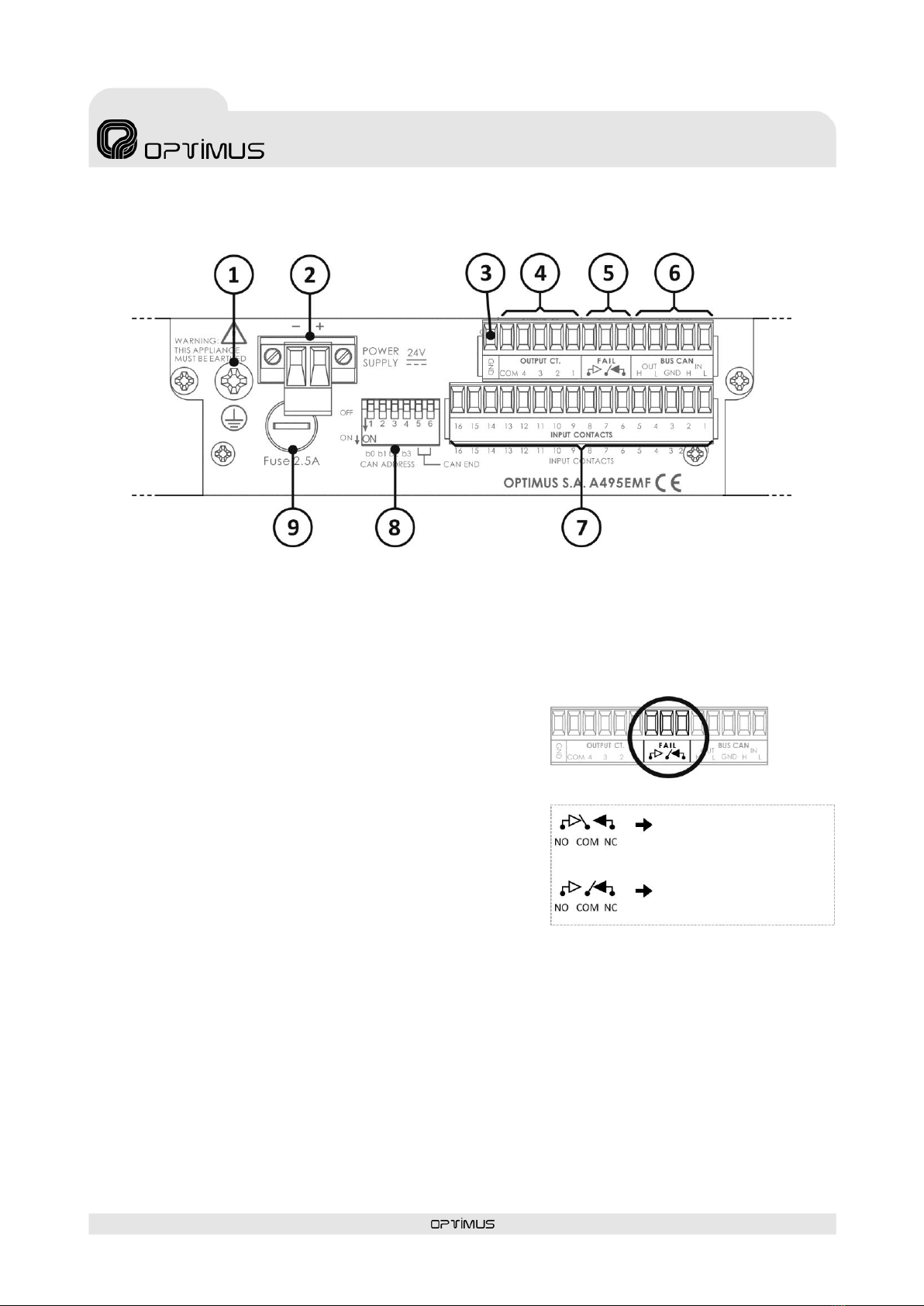
3.1. Communication and control module ....................................................................................................7
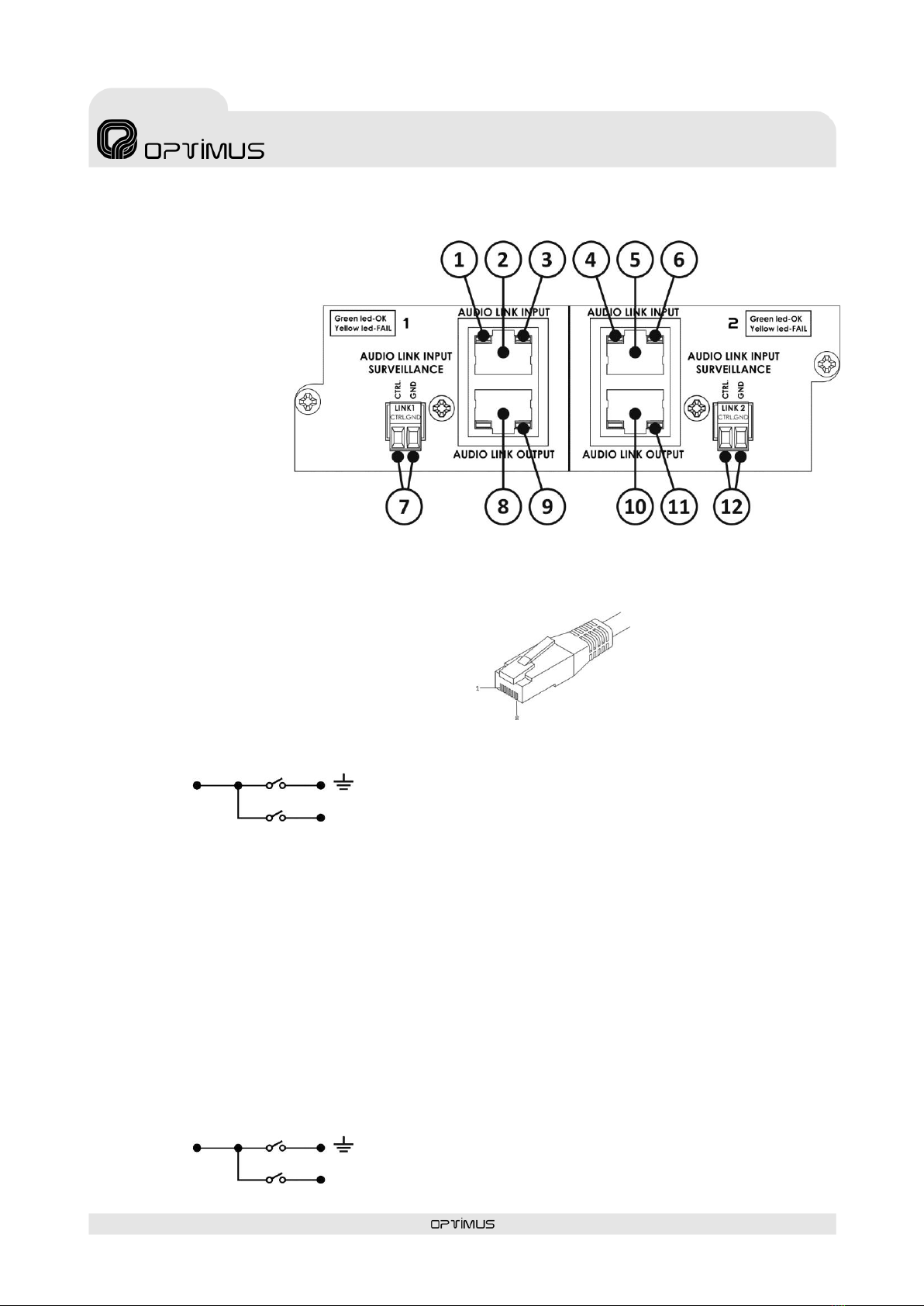
3.2. Audio expansion module ......................................................................................................................8
4. CONNECTION .......................................................................................................................................10
4.1. Speakers connection ...........................................................................................................................10
4.2. Local Audio Inputs connection ............................................................................................................12
4.3. Power supply ......................................................................................................................................13
4.4. Input contacts .....................................................................................................................................14
4.5. Output Contacts..................................................................................................................................14
4.6. Audio link between matrixes ..............................................................................................................15
4.7. CAN BUS connection ...........................................................................................................................16
5. CAN BUS CONFIGURATION....................................................................................................................16
6. INSERTING THE POWER AMPLIFIERS MODULES .....................................................................................17
7. COMMISSIONING THE UNIT ..................................................................................................................19
8. SYSTEM ALARMS ..................................................................................................................................20
9. TECHNICAL CHARACTERISTICS...............................................................................................................20
10. MODULAR AMPLIFIERS MP-WD1 SERIE .................................................................................................21
11. SOFTWARE AND FIRMWARE VERSIONS .................................................................................................22
12. DOCUMENT VERSION TRACKING...........................................................................................................22
13. GUARANTEE .........................................................................................................................................23
WARNING. This is a Class A unit. In a domestic environment this unit may cause radio interferences. In this case the user
must take the necessary precautions.

IF-7P4/0E version 5.0.001 ENG
4
Audio IP Mainframe
expansion unit
IF-7P4/0E
R + D Department
1. INTRODUCTION
Audio matrix expansion unit for COMPACT Systems.
It has four slots that allow to insert module amplifiers from MP-WD1* series (not included) and four local analog inputs (program
/priority) of configurable sensitivity.
Each zone output has connections for A / B lines (not implemented) and input for backup amplifier.
Communicates with the main IF-7P4ETH/0 unit or COMPACT unit via CAN bus. Each main unit can control up to 10 IF-7P4/0E units.
*Module amplifiers available: 120 W, 150 W, 250 W, 300 W & 460 W
Main characteristics:
4 Slots for modular amplifiers.
4 Zone outputs with DSP functions (controls for volume, bass and treble) and surveillance functions (speakers lines and amplifi-
er status).
4 local analog inputs (configurable -6dB, -3dB, 0dB, +3dB, +6dB) with priority control.
16 Input contacts. They may be configured as general purpose contacts or in the evacuation system as Emergency Mode activa-
tion contacts, evacuation message activated... The system may monitor these contacts (short-circuit or open line detection).
4 Output contacts. They may be configured as general purpose contacts or in the evacuation system as fault notification con-
tacts, Emergency Mode indicator activated...
Fail relay. Switches when a system alarm is detected.
Reception and sending of control data via CAN Bus.
It is equipped with a full range power supply (100-240Vac 50/60 Hz) as well as a secondary 24 VDC input (only for the control
part).

IF-7P4/0E version 5.0.001 ENG
5
Audio IP Mainframe
expansion unit
IF-7P4/0E
R + D Department
2. FRONT VIEW
1. Slot 1 for amplifier module (amplifier not included).
2. Slot 2 for amplifier module (amplifier not included).
3. Slot 3 for amplifier module (amplifier not included).
4. Slot 4 for amplifier module (amplifier not included).
5. Amplifier module POWER LED indication (see section 10).
6. Amplifier module STANDBY LED indication (see section
10).
7. Amplifier module PROTECT LED indication (see section
10).
8. Amplifier module CLIP LED indication (see section 10).
9. Amplifier module SIGNAL LED indication (see section 10).
10. INPUT CONTACT activation LEDs.
11. OUTPUT CONTACT activation LEDs.
12. GENERAL FAULT LED.
13. SYSTEM FAULT LED.
14. EMERGENCY LED.
15. POWER SUPPLY LED.
16. Buzzer. Acoustic alarm.
Figure 1

IF-7P4/0E version 5.0.001 ENG
6
Audio IP Mainframe
expansion unit
IF-7P4/0E
R + D Department
3. REAR VIEW
1) Surety paging options module space.
2) Speakers line output connection for CHANNEL 4 (lines 4A and 4B*) and 100V input of the BACKUP 4 amplifier.
3) Speakers line output connection for CHANNEL 3 (lines 3A and 3B*) and 100V input of the BACKUP 3 amplifier.
4) Speakers line output connection for CHANNEL 2 (lines 2A and 2B*) and 100V input of the BACKUP 2 amplifier.
5) Speakers line output connection for CHANNEL 1 (lines 1A and 1B*) and 100V input of the BACKUP 1 amplifier.
6) Input CHANNEL 4. Local audio input corresponding to slot 4 amplifier.
7) Input CHANNEL 3. Local audio input corresponding to slot 3 amplifier.
8) Input CHANNEL 2. Local audio input corresponding to slot 2 amplifier.
9) Input CHANNEL 1. Local audio input corresponding to slot 1 amplifier.
10) PROGRAM/PRIORITY DIP switches. Program/priority configuration of analog local inputs.
11) Mains fuse (15A).
12) ON/OFF Switch.
13) 100-240V AC 50/60 Hz Power entry connector.
14) Communication and control module (see section 3.1).
15) Audio expansion module (see section 3.2).
Figure 2
* A/B Lines functionality not implemented

IF-7P4/0E version 5.0.001 ENG
7
Audio IP Mainframe
expansion unit
IF-7P4/0E
R + D Department
3.1. Communication and control module
1) Ground connection.
2) POWER SUPPLY.
24 VDC Secondary power supply input. Only power the control module. Optional, may be connected if required by the safety
standards.
3) GND Contact.
4) OUTPUT Contacts CT 1, 2, 3, 4 and COM. See section 4.5 Output
Contacts.
5) FAIL Contacts.
Output relay used to indicate a system failure.
If the COM contact is linked to the NO contact, it indicates that there
are no faults or alarms in the system. If on the other hand, COM is
linked to NC, it indicates that the equipment is switched OFF or that
alarms were detected (figure 4).
Maximum DC charge current: 150mA
Maximum DC or AC peak charge voltage: 350V
6) CAN BUS Contacts. See section 4.7. CAN BUS connection.
7) INPUT contacts CT 1 to 16. See section 4.4. Input contacts.
8) CAN BUS Configuration DIP Switches. See section 5. CAN BUS CONFIGURATION.
9) FUSE. 2.5A Fuse. Secondary power supply fuse.
Figure 3
FAIL RELAY STATUS
IF-7P4/0E is turned off or alarms
detected
No alarms
Figure 4

IF-7P4/0E version 5.0.001 ENG
8
Audio IP Mainframe
expansion unit
IF-7P4/0E
R + D Department
3.2.Audio expansion module
Audio link module between
master matrix (IF-7P4ETH/0
or COMPACT) and slave
matrix (IF-7P4/0E), or
between slave matrixes IF-
7P4/0E.
It allows linking 4 audio
channels (music or
announcements) and an
emergency channel between
matrices using RJ45
connectors.
1) Yellow LED. If it turns ON it indicates that the AUDIO LINK INPUT 1 connection failed or was disconnected.
2) RJ45 connector AUDIO LINK INPUT 1.
Pin 1: CHANNEL 1 AUDIO INPUT HOT.
Pin 2: CHANNEL 1 AUDIO INPUT COLD.
Pin 3: CHANNEL 2 AUDIO INPUT HOT.
Pin 4: CHANNEL 3 AUDIO INPUT COLD.
Pin 5: CHANNEL 3 AUDIO INPUT HOT.
Pin 6: CHANNEL 2 AUDIO INPUT COLD.
Pin 7: INPUT SURVEILLANCE LINK 1.
Pin 8: GND.
Metal Shield:
3) Green LED. Shows the status of the AUDIO LINK INPUT 1 connection. LED ON indicates correct connection
4) Yellow LED. If it turns ON it indicates that the AUDIO LINK INPUT 2 connection failed or was disconnected
5) RJ45 connector AUDIO LINK INPUT 2.
Pin 1: EMERGENCY CHANNEL AUDIO INPUT HOT.
Pin 2: EMERGENCY CHANNEL AUDIO INPUT COLD.
Pin 3: 24 VDC LINK (Degraded mode functionalities: Through pin 3, the audio expansion module is powered from the other
matrices, which guarantees its operation even in the event that the matrix itself is not powered).
Pin 4: CHANNEL 4 AUDIO INPUT COLD.
Pin 5: CHANNEL 4 AUDIO INPUT HOT.
Pin 6: EMERGENCY PRIORITY INPUT CONTACT.
Pin 7: INPUT SURVEILLANCE LINK 2.
Pin 8: GND.
Metal Shield:
GND
* In the AUDIO LINK INPUT 2 connector, the connection to the chassis of
the equipment is made through the Internal DIP Switch 8 and the con-
nection between the shielding of the connector to the GND is made
through the internal DIP Switch 7.
*DIP Switch 8
* DIP Switch 7
Figure 6
GND
* In the AUDIO LINK INPUT 1 connector, the connection to the chassis of
the equipment is made through the Internal DIP Switch 5 and the con-
nection between the shielding of the connector to the GND is made
through the internal DIP Switch 6.
*DIP Switch 5
* DIP Switch 6
Figure 5

IF-7P4/0E version 5.0.001 ENG
9
Audio IP Mainframe
expansion unit
IF-7P4/0E
R + D Department
6) Green LED. Shows the status of the AUDIO LINK INPUT 2 connection. LED ON indicates correct connection.
7) AUDIO LINK INPUT 1 SURVEILLANCE.
Open collector output contact. Normally open contact. The contact closes when a
fault is detected in the cable connection AUDIO LINK INPUT 1.
8) RJ45 connector AUDIO LINK OUTPUT 1.
RJ45 PIN OUT
Pin 1: CHANNEL 1 AUDIO OUTPUT HOT.
Pin 2: CHANNEL 1 AUDIO OUTPUT COLD.
Pin 3: CHANNEL 2 AUDIO OUTPUT HOT.
Pin 4: CHANNEL 3 AUDIO OUTPUT COLD.
Pin 5: CHANNEL 3 AUDIO OUTPUT HOT.
Pin 6: CHANNEL 2 AUDIO OUTPUT COLD.
Pin 7: OUTPUT SURVEILLANCE LINK 1.
Pin 8: GND.
Metal Shield:
9) Power LED indicator. Indicates that the audio expansion module is powered, either through the audio matrix itself or through
the link with the other matrices through pin 3 of the AUDIO LINK INPUT 2 and AUDIO LINK OUTPUT 2 connectors.
10) RJ45 connector AUDIO LINK OUTPUT 2.
Pin 1: EMERGENCY CHANNEL AUDIO OUTPUT HOT.
Pin 2: EMERGENCY CHANNEL AUDIO OUTPUT COLD.
Pin 3: 24 VDC LINK (Degraded mode functionalities: Through pin 3, the audio expansion module is powered from the other
matrices, which guarantees its operation even in the event that the matrix itself is not powered).
Pin 4: CHANNEL 4 AUDIO OUTPUT COLD.
Pin 5: CHANNEL 4 AUDIO OUTPUT HOT.
Pin 6: EMERGENCY PRIORITY OUTPUT CONTACT.
Pin 7: OUTPUT SURVEILLANCE LINK 2.
Pin 8: GND.
Metal Shield:
11) Power LED indicator. Indicates that the audio expansion module is powered, either through the audio matrix itself or through
the link with the other matrices through pin 3 of the AUDIO LINK INPUT 2 and AUDIO LINK OUTPUT 2 connectors.
12) AUDIO LINK INPUT 2 SURVEILLANCE.
Open collector output contact. Normally open contact. The contact closes when a fault is detected in the cable connection
AUDIO LINK INPUT 2. See Figure 7.
Figure 7.
OPEN COLLECTOR CONTACT SCHEME
GND
* In the AUDIO LINK OUTPUT 1 connector, the connection to the chassis of the equip-
ment is made through the Internal DIP Switch 5 and the connection between the
shielding of the connector to the GND is made through the internal DIP Switch 6.
*DIP Switch 5
* DIP Switch 6
GND
* In the AUDIO LINK OUTPUT 2 connector, the connection to the chassis of the equip-
ment is made through the Internal DIP Switch 8 and the connection between the
shielding of the connector to the GND is made through the internal DIP Switch 7.
*DIP Switch 8
* DIP Switch 7

IF-7P4/0E version 5.0.001 ENG
10
Audio IP Mainframe
expansion unit
IF-7P4/0E
R + D Department
4. CONNECTION
4.1.Speakers connection
The equipment has four channels (one per amplifier) for the connection of 100V high impedance speaker lines.
Each channel also has connections for A / B lines for installations with redundant loudspeaker lines (not implemented) and a
backup amplifier input.
Figure 8
4 ZONES SPEAKER LINES CONNECTION
IF-7P4/0E
ZONE
AMPLIFIER
ZONE
AMPLIFIER
ZONE
AMPLIFIER
ZONE
AMPLIFIER

IF-7P4/0E version 5.0.001 ENG
11
Audio IP Mainframe
expansion unit
IF-7P4/0E
R + D Department
WARNING:
The sum of the power ratings of the loudspeakers connected to output of an amplifier must not exceed the
power of the amplifier module.
The backup amplifier must be at least the most powerful of the amplifiers you must replace.
Figure 9
SPEAKER LINES CONNECTION
3 ZONE AMPLIFIERS + 1 BACKUP AMPLIFIER
IF-7P4/0E
BACKUP
AMPLIFIER
ZONE
AMPLIFIER
ZONE
AMPLIFIER
ZONE
AMPLIFIER

IF-7P4/0E version 5.0.001 ENG
12
Audio IP Mainframe
expansion unit
IF-7P4/0E
R + D Department
4.2.Local Audio Inputs connection
Each of the inputs corresponds to a channel (CHANNELS 1, 2, 3 and 4), and each channel corresponds to an amplifier. In this way,
the CHANNEL 1 input corresponds to the amplifier inserted in slot 1, the CHANNEL 2 input corresponds to the amplifier inserted in
SLOT 2, the CHANNEL 3 input corresponds to the amplifier inserted in SLOT 3 and the CHANNEL 4 input corresponds to the
amplifier inserted in SLOT 4.
These inputs are balanced by transformer, with a configurable sensitivity using the PA Manager software: -6dB, -3dB, 0dB, + 3dB, +
6dB.
Using DIP Switches, local inputs can be configured as program or priority inputs. In the PROGRAM position, the audio applied to the
input is sent directly to the amplifier of the corresponding channel. In the PRIORITY position, the audio applied to the input will be
sent to the corresponding amplifier when the priority contact (PRI) is connected to ground (GND).
Figure 10
Figure 11
H
HOT Audio input
GND
Ground
C
COLD Audio input
PRI
Priority control contact. By joining this
contact to ground (GND) through an
external device, the signal applied to
the input attacks the corresponding
amplifier.
ACK
Acknowledge output contact. By
closing that contact the equipment
confirms that the priority channel is
activated and ready.

IF-7P4/0E version 5.0.001 ENG
13
Audio IP Mainframe
expansion unit
IF-7P4/0E
R + D Department
4.3.Power supply
The equipment has a 100-240VAC power input which allows the connection of the equipment to the mains by means of the
supplied cable.
If required, a secondary power supply input of 24VDC that will supply ONLY the control module of the mainframe.
PRIMARY
POWER SUPPLY
SECONDARY
POWER SUPPLY
24VDC POWER SUPPLY
I924UP
(Not included)
Figure 14
Figure 12
Balanced audio connection
to a local audio input of the IF-7P4/0E
Figure 13
Unbalanced audio connection
to a local audio input of the IF-7P4/0E
AUDIO –
AUDIO +
GROUND
AUDIO +
GROUND
External
equipment
External
equipment

IF-7P4/0E version 5.0.001 ENG
14
Audio IP Mainframe
expansion unit
IF-7P4/0E
R + D Department
External
device
4.4.Input contacts
Incorporates 16 input contacts.
The functionality and stand-by state (NC/NO) are configured through the PA Manager software. They may be configured as general
purpose contacts or in the evacuation system as emergency mode activation contacts, evacuation message activated...
The detection time of the activation pulse of the input contacts is configurable through the Call Point software (0-50-100-200-300-
400-500-1000-1500-2000 milliseconds).
If you wish, the system may monitor these contacts (short-circuit or open line detection).
To connect follow figure 15. If you wish to monitor the contact, follow figure 16.
4.5.Output Contacts
The unit incorporates four output contacts referenced to a common contact (COM).
There are dry contacts.
The functionality and standby state (NC/NO) are configured through the PA Manager software. They may be configured as general
purpose contacts or in the evacuation system as fault notification contacts, Emergency Mode indicator activated...
Maximum DC charge current: 150mA
Maximum DC or AC peak charge voltage: 350V
To connect please follow figure 17.
Figure 15
Figure 16
Figure 17

IF-7P4/0E version 5.0.001 ENG
15
Audio IP Mainframe
expansion unit
IF-7P4/0E
R + D Department
Audio channels
1, 2 & 3
Audio channel 4
& Emergency audio channel
l
Audio channels
1, 2 & 3
Audio channel 4
& Emergency audio channel
4.6.Audio link between matrixes
Use the AUDIO LINK INPUT and AUDIO LINK OUTPUT connectors to connect the different audio matrices together, expanding the
audio bus.
If you wish, you can monitor the AUDIO INPUT LINK connections by connecting the CTRL contacts to the input contacts of the
control module. Use the PA Manager software to configure these contacts for this purpose.
Figure 18
Figure 19

IF-7P4/0E version 5.0.001 ENG
16
Audio IP Mainframe
expansion unit
IF-7P4/0E
R + D Department
Figure 22. CAN BUS POSITION
BUS INTERMEDIATE
ELEMENT
BUS END ELEMENT
(FACTORY SETUP)
(TEST MODE)
SETUP)
Figure 23. CAN BUS ADDRESSES
(FACTORY SETUP)
4.7.CAN BUS connection
Data communication bus between the master matrix (COMPACT or IF-
7P4ETH/0) and the IF-7P4/0E.
Speed transmission: 500 kbit/s.
To connect them it is recommended to use a shielded twisted pair
AWG24 cable.
Follow figure 20 if the IF-7P4/0E unit is an intermediate element of the
CAN bus or follow figure 21 if it is an end element.
ATTENTION: Configure external DIP switches 5 and 6 to indicate
the position on the CAN bus occupied by the IF-7P4/0E (end
element or intermediate element). To configure follow section 5.
ATTENTION: In installations with slave matrices and CAN
peripherals (MD-30C, ME-200C, NS-CAN ...) a CAN-AV module is
necessary. This module adapts the communication speed of the
slave matrix (500 kbit/s) to the communication speed of the
peripherals (33.3 kbit/s).
5. CAN BUS CONFIGURATION
It allows configuring the occupied position in the CAN bus (final element or intermediate element) and the CAN address of the
equipment:
CAN Bus position
Configure external DIP switches 5 and 6 to indicate the position on the CAN bus occupied by the IF-7P4/0E (end element or
intermediate element). See figure 22.
CAN Address
Each IF-7P4/0E that is connected to the CAN bus must have a different address. This DIP switches b0, b1, b2 and b3 allows assigning
this communication address.
Each master audio matrix (IF-7P4ETH/0 or COMPACT) may be expanded with a maximum of 10 IF-7P4/0E units and if this were to
happen, then 10 different CAN addresses would be used.
Figure 23 shows the DIP switches b0, b1, b2 and b3 combinations to assign the CAN addresses for 1 through 10.
Figure 20
Figure 21

IF-7P4/0E version 5.0.001 ENG
17
Audio IP Mainframe
expansion unit
IF-7P4/0E
R + D Department
6. INSERTING THE POWER AMPLIFIERS MODULES
1. Remove the frontal plate.
2. If you want to use slots 2, 3 or 4, remove
the corresponding slot panel.
Figure 24
Figure 25

IF-7P4/0E version 5.0.001 ENG
18
Audio IP Mainframe
expansion unit
IF-7P4/0E
R + D Department
3. Insert the amplifier module by fitting it
into the slot guides.
4. Fasten the amplifier module by means of
the hot-swapping screw.
Figure 27
Figure 26
Table of contents
Languages:
Other Opvimus Recording Equipment manuals