Opvimus IF-704ETH User manual


0
9I330B 07/10/2020 V5.0.001

IF-704ETH version 5.0.001
2
IP Audio interface
with 4 outputs
IF-704ETH
R+D Department
Table of contents
1. INTRODUCTION ..................................................................................................................................................................... 3
2. FRONT VIEW.......................................................................................................................................................................... 4
3. REAR VIEW ............................................................................................................................................................................ 4
3.1. IP Connection, communication and control module .....................................................................................................5
3.2. Audio outputs modules .................................................................................................................................................6
4. PLACEMENT OF THE BATTERY................................................................................................................................................ 7
5. CONNECTION......................................................................................................................................................................... 9
5.1. Power supply .................................................................................................................................................................9
5.2. Output zones connection ..............................................................................................................................................9
5.2.1. Speakers line connection without surveillance ..................................................................................................9
5.2.2. Speakers line connection with surveillance .....................................................................................................10
5.3. Input contacts..............................................................................................................................................................10
5.4. Output contacts...........................................................................................................................................................11
5.5. BUS CAN connection ...................................................................................................................................................11
5.6. Front USB connector: Playing music from an external memory..................................................................................11
6. COMMISSIONING THE UNIT................................................................................................................................................. 12
6.1. Configuration of the IF-704ETH network addresses....................................................................................................12
7. SYSTEM ALARMS ................................................................................................................................................................. 13
8. TECHNICAL CHARACTERISTICS ............................................................................................................................................. 14
9. COMPACT SYSTEM NETWORK SPECIFICATIONS ................................................................................................................... 15
10. SOFTWARE AND FIRMWARE VERSIONS ............................................................................................................................... 18
11. DOCUMENT VERSION TRACKING ......................................................................................................................................... 18
12. GUARANTEE ........................................................................................................................................................................ 19
WARNING. This is a Class A unit. In a domestic environment this unit may cause radio interferences. In this case the user
must take the necessary precautions.

IF-704ETH version 5.0.001
3
IP Audio interface
with 4 outputs
IF-704ETH
R+D Department
1. INTRODUCTION
Audio interface with IP connection for COMPACT system.
Incorporates four zone outputs (2 modules with 2 zones each one), with DSP and monitoring functions.
Main characteristics:
Dual Ethernet connection for installations with redundant
network systems. The connection is constantly monitored
and switches automatically when required.
It is equipped with two power supplies for redundant
installations (primary at 100-240Vac 50/60 Hz and
secondary at 24 VDC).
Four zone outputs Incorporates DSP and monitoring
functions.
DSP functions:
Controls for volume controls, bass and treble or 10-band
graphic equalizer (30Hz / 60Hz / 125Hz / 250Hz / 500Hz /
1KHz / 2KHz / 4KHz / 8KHz / 16KHz) controlled by means
the Call Point software
Monitoring functions:
Monitoring of the speaker line: To accomplish this the
card injects different frequencies in the speaker line; it
then collects and analyses these frequencies to
determine the condition of the line (line open, short-
circuit, low impedance, high impedance or line in good
condition).
Monitoring of the condition of the amplifier by
analysing the audio signal to detect if the power stage has
entered into protection mode or is turned off and by
detecting the 24 VDC it receives from the amplifier.
Front USB input for music.
CAN bus for communicating with the peripherals (NS-
CAN, MD-30C, ME-200C).
Reception of digital audio via an IP connection (4
simultaneous channels).
Reception and sending of control data via an IP
connection.
Monitoring of the operation of the equipment using Call
Point software and/or basic TELNET or SSH (Secure Shell)
functions.
Configuration of the IP address in Flash memory via
software.
Constant notification (IP) of the status of the equipment
via a Heart Beat signal.
Pre-recorded messages residing in the equipment that
can be remotely updated using the Call Point software via
IP located in the internal Micro SD memory (16 GB).
Monitoring functions:
-of the speaker lines (short-circuit and open line).
-of the amplifiers.
-of the primary and secondary power supplies.
-of the input contacts.
-of the pre-recorded messages.
Communication with external systems:
-VoIP: receiving of direct calls from any VoIP digital
telephone that uses standard SIP protocols.
Incorporates zone selection by sending DTMF tones.
Provides the possibility of protecting the access with a
password.
-Direct integration (XML, API/DLL).

IF-704ETH version 5.0.001
4
IP Audio interface
with 4 outputs
IF-704ETH
R+D Department
2. FRONT VIEW
(1) GENERAL FAULT indicator light.
Yellow LED system alarm indicator.
(2) SYSTEM FAULT indicator light.
Yellow LED internal equipment error indicator.
(3) EMERGENCY indicator light.
Red LED emergency indicator. Remains illuminated while
the system is in Emergency Mode.
(4) POWER indicator.
Indicates that the unit is receiving power.
(5) Buzzer.
The IF-704ETH incorporates a buzzer that generates an
acoustic signal when an alarm is received.
(6) Internal jumper for deactivating the acoustic alarm in
SYSTEM FAULT errors.
(7) CONSOLE connector.
Mini USB connector. Allows monitoring the system. Only
specialised personnel.
(8) Front USB for inputting music.
3. REAR VIEW
100-240V AC 50/60 Hz Power supply input. Male socket1)
CEE22 for connection to the mains supply by means of
the cable supplied together with the IF-704ETH.
Mains fuse (3.15A). There is also a spare fuse in the same2)
box.
ON/OFF Switch. Switch for turning on the equipment. If3)
the IF-704ETH is operating by secondary power supply
(24VDC input), this switch has no effect.
Battery holder. See section 4.4)
IP Connection, communication and control module. See5)
section 3.1.
Audio outputs modules. See section 3.2.6)
Figure 1
Figure 2

IF-704ETH version 5.0.001
5
IP Audio interface
with 4 outputs
IF-704ETH
R+D Department
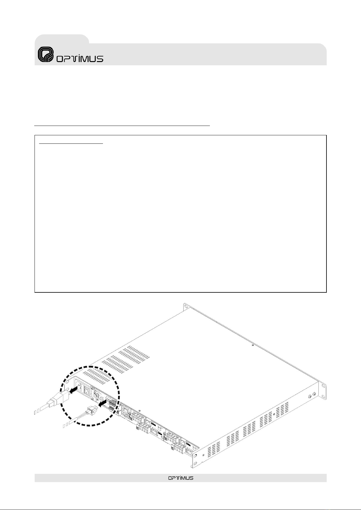
3.1.IP Connection, communication and control module
Ground connection1)
FUSE. 2.5 A Secondary power supply fuse.2)
POWER SUPPLY 23)
24 VDC Secondary power input.
GND Contact4)
FAIL Contacts5)
Output relay used to indicate a system failure.
If the COM contact is linked to the NO contact, it
indicates that there are no faults or alarms in the
system. If on the other hand, COM is linked to NC, it
indicates that the equipment is switched off or that
alarms were detected (figure 4).
Maximum DC charge current: 150 mA
Maximum DC or AC peak charge voltage: 350 V
BUS CAN Contacts6)
Data communication bus between the IF-704ETH and
the system peripherals (MD-30C, ME-200C, NS-CAN).
OUTPUT CT Contacts7)
Incorporates three output contacts configured as dry
contacts. Each contact has two terminals (A and B).
The functionality and stand-by state (NC/NO) are
configured through the Call Point software. They may be
configured as general purpose contacts or in the
evacuation system as fault notification contacts,
Emergency Mode indicator activated...
INPUT Contacts CT 1, 2 and 38)
Incorporates three input contacts.
The functionality and stand-by state (NC/NO) are
configured through the Call Point software. They may be
configured as general purpose contacts or in the
evacuation system as emergency mode activation
contacts, evacuation message activated...
The detection time of the activation pulse of the input
contacts is configurable through the Call Point software
(0-50-100-200-300-400-500-1000-1500-2000
milliseconds).
If you wish, the system may monitor these contacts
(short-circuit or open line detection).
ETH B Connector9)
Is used in a redundant network as a secondary
connection to the IP network.
ETH A Connector10)
Is used to connect the unit to the IP network.
LINK/ACTIVITY indicator (green LED):11)
When illuminated it indicates a network connection.
When flashing it indicates that data is being sent or
received.
SPEED indicator (yellow LED):12)
Speed of the network. If the LED is lit, indicates a speed
of 100 Mbps. If unlit, indicates a network speed of 10
Mbps (it is highly recommended to use a transmission
speed of 100 Mbps).
Figure 4
No alarms
COMPACT is turned off
or alarms detected
Figure 3
FAIL RELAY STATUS

IF-704ETH version 5.0.001
6
IP Audio interface
with 4 outputs
IF-704ETH
R+D Department
3.2.Audio outputs modules
Channel “A”FAIL Contact. NO (Normally Open) output contact. Its activation is associated with1)
the surveillance functions of the “A”channel. Use the software P.A. Manager to configure in
which cases the contact is activated (by detecting errors loudspeaker line high or low
impedance, short circuit, open line or error amplifier...).
FAIL contact is an open collector output as shown in the diagram of figure 6.
CHANNEL “A”LINE IN 0 & 100V. Channel “A”amplifier speakers line connection.2)
CHANNEL “A”LINE OUT 0 & 100V. Channel “A”speakers line connection.3)
CHANNEL “A” RJ45 Connector. +4dB audio output, balanced through transformer. The output4)
level is adjustable through Call Point software.
RJ45 PIN OUT
Pin 1: AUDIO H (HOT) output signal.
Pin 2: AUDIO C (COLD) output signal.
Pin 3: +24 VDC input to monitoring the amplifier.
Pin 4: Not used.
Pin 5: Not used.
Pin 6: PRIORITY output contact. Open collector output.
Pin 7: Not used.
Pin 8:
Metal Shield:
OUTPUT “A”FAIL LED indicator. Indicates FAIL output contact activated.5)
OUTPUT “A”PRIORITY LED indicator. Indicates activation of the channel “A”priority output contact (pin 6 of the OUTPUT “A”6)
RJ45 connector).
CHANNEL “B”indicators and connectors. It has the same functionalities as the elements of channel “A”, applied in this case to7)
channel “B”.
POWER LED indicator. Indicates that the audio outputs module is supplied.8)
Figure 5
Internal jumper
JP3 *
GND
Internal jumper
JP5*
Figure 6
FAIL contact
open collector output
schema
* In the RJ45 connector of channel “B”, the connection
between the pin 8 and the shielding of the connector
to the GND is made through the internal jumper JP1,
and the connection to the earth of the equipment is
made through the Internal jumper JP6.

IF-704ETH version 5.0.001
7
IP Audio interface
with 4 outputs
IF-704ETH
R+D Department
Handling batteries properly:
Warning! Improper use of battery may lead to explosion. Replace the batteries with the same or equivalent type only.
Batteries may endanger life if swallowed. If a battery is swallowed, seek medical assistance immediately.
Before inserting the batteries, check whether the contacts in the device and batteries are clean and, if necessary, clean
them.
Only use new batteries.
Do not use rechargeable batteries
Never try to recharge normal batteries. There is a risk of explosion!
Never expose batteries to heat sources (e.g. radiators) or direct sunlight. There is an increased risk of leakage!
Never short-circuit the batteries.
Never throw batteries into a fire.
Do not disassemble or deform batteries.
If the equipment is not going to be used for long periods, remove the battery.
Remove leaking batteries from the device immediately. If battery acid leaks out it is essential to avoid contact with the skin,
eyes and mucous membranes! If the acid does come into contact with skin, immediately rinse the affected areas with plen-
ty of clear water and consult a doctor immediately. There is a risk of acid poisoning and acid burns!
Remove exhausted rechargeable battery from the device immediately! There is an increased risk of leakage
Do not throw used batteries into the household waste. The batteries must be deposited in a collection point for used bat-
teries.
4. PLACEMENT OF THE BATTERY
To activate the time schedules, the equipment incorporates an RTC (Real-time clock) whose function is to maintain the current
time. To keep the RTC powered even if the equipment is turned off, we must place a 3V lithium battery type CR2032 supplied with
the equipment.
It is advisable to replace the equipment battery at least every 5 years.
Battery placement procedure:
Disconnect the device from the power supply.1)

IF-704ETH version 5.0.001
8
IP Audio interface
with 4 outputs
IF-704ETH
R+D Department
Unscrew and pull out the battery compartment.2)
Insert the battery respecting the polarity3)
indicated in the attached figure.
Insert and screw the battery4)
compartment and connect the
power again
2)
3)
4)

IF-704ETH version 5.0.001
9
IP Audio interface
with 4 outputs
IF-704ETH
R+D Department
RJ45 OUTPUT “A”and OUTPUT “B”CONNECTORS PINOUT
Pin 1: AUDIO H output (HOT)
Pin 2: AUDIO C output (COLD)
Pin 3: +24 VDC input to monitoring the amplifier.
Pin 4: Not used.
Pin 5: Not used.
Pin 6: PRIORITY output contact.
Pin 7: Not used.
Pin 8:
Metal Shield:
5. CONNECTION
5.1.Power supply
The equipment has a 100-240VAC power input which allows the connection of the
equipment to the mains by means of the supplied cable, and if required by safety
standards, a secondary power supply input of 24 VDC.
5.2.Output zones connection
5.2.1. Speakers line connection without surveillance
PRIMARY
POWER SUPPLY
SECONDARY
POWER SUPPLY
24VDC
POWER SUPPLY
I924UP (not included)
ZONE 1
AMPLIFIER
ZONE 1 SPEAKERS LINE
SPEAKERS
LINE OUTPUT
INPUT
ZONA 2
AMPLIFIER
ZONE 2 SPEAKERS LINE
SPEAKERS
LINE OUTPUT
INPUT
GND
Internal jumper
JP3/JP1
Internal jumper
JP5/JP6

IF-704ETH version 5.0.001
10
IP Audio interface
with 4 outputs
IF-704ETH
R+D Department
5.2.2. Speakers line connection with surveillance
5.3.Input contacts
The IF-704ETH incorporates three input contacts (INPUT CT 1, 2 and 3).
If you wish, the system may monitor these contacts (short-circuit or open line detection).
ZONE 1
AMPLIFIER
ZONE 1 SPEAKERS LINE
SPEAKERS
LINE OUTPUT
INPUT
INPUT CONTACT CONNECTION
WITHOUT SURVEILLANCE
INPUT CONTACT CONNECTION
WITH SURVEILLANCE

IF-704ETH version 5.0.001
11
IP Audio interface
with 4 outputs
IF-704ETH
R+D Department
5.4.Output contacts
The IF-704ETH incorporates three output contacts.
Each contact has two terminals (A and B) configured as dry contacts.
5.5.BUS CAN connection
The IF-704ETH communicates with the
installation CAN peripherals (MD-30C,
ME-200C, NS-CAN...) at a transmission
speed of 33.3kbit/s.
For the connection of the CAN bus it is
recommended to use a shielded twisted
pair AWG24 cable.
5.6.Front USB connector: Playing music from an external memory
The unit has a USB 2.0 port on the front panel for use as a musical program input. To do this, connect to this port an external
memory that contains audio files in MP3, WAV or OGG format.
Through the Call Point software you can configure the parameters corresponding to this music program (random playback of audio
files, music activated or deactivated by zones ...).
EXTERNAL
DEVICE
(Not connected)
CAN PERIPHERAL
(MD-30C, NS-CAN, ME-200C…)

IF-704ETH version 5.0.001
12
IP Audio interface
with 4 outputs
IF-704ETH
R+D Department
6. COMMISSIONING THE UNIT
To commission the IF-704ETH we must send configurations to it via an Ethernet connection. Accomplishing this requires a PC
equipped with a network card and connected to the unit through a switch or directly using a network cable. The PC must have the
Call Point software installed.
1. Make the connections between units.
2. Apply power to the units.
3. Via the Call Point software, configure the parameters of the IF-704ETH and send the settings to the unit.
6.1. Configuration of the IF-704ETH network addresses
To change the unit's network settings by default, carry out the following:
1. From the PC, open a browser, enter the IP address for the unit and press
INTRO. By default the IP address is 10.1.1.1. Warning: The range of IP
addresses for the unit and the PC must match. Otherwise, the network
settings of the PC must be changed first in order to place it within the range of
the unit (for example, the PC could have an IP address of 10.1.100.152).
2. Enter the user name optimax, the password
1933 and click on the Login button
WARNING
To send configurations to the unit requires having the unit and the PC within the same IP address range. The unit's
network addresses and those set via the configuration software must match.
By default, the network configurations of the unit are the following:
IP ADDRESS: 10.1.1.1
NETMASK: 255.0.0.0
GATETEWAY: 0.0.0.0 (without Gateway)
If you wish to assign a different network address to the equipment, other than the one established by default, refer
to the following section 6.1. Configuration of the IF-704ETH network addresses.

IF-704ETH version 5.0.001
13
IP Audio interface
with 4 outputs
IF-704ETH
R+D Department
3. Click on Network.
4. Modify the network
parameters as desired (IP,
Netmask and Gateway)
and click on the Change
Network Settings button
to apply the changes.
The equipment will
reboot automatically.
7. SYSTEM ALARMS
The unit incorporates several alarm systems that indicate that a fault has occurred in a component of the PA system.
GENERAL FAULT indicator light: Front yellow LED. Illuminates when the unit receives one or several alarms from the system or
when an alarm is generated by the unit itself.
SYSTEM FAULT indicator light: Front yellow LED. Illuminates when the equipment detects an internal error.
Acoustic alarm indicator (buzzer): Intermittent buzzing sound. The IF-704ETH incorporates a buzzer that generates an acoustic
signal each time an alarm is received. The acoustic indication is a buzzing sound that lasts 10 seconds and is periodically
repeated every 20 seconds. The buzzer may be deactivated through the Call Point software.
It is possible to disable the buzzer for the SYSTEM FAULT alarm (internal device error). To do this, remove the front cover and
remove the jumper JP1.
JP1

IF-704ETH version 5.0.001
14
IP Audio interface
with 4 outputs
IF-704ETH
R+D Department
8. TECHNICAL CHARACTERISTICS
Ethernet communication
2 Ethernet connections (RJ45) A and B for redundant installations. IP Layer 3 & Layer
4Network.
CAN Bus
Speed : 500kbit/s or 33.3kbit/s
VoIP
SIP RFC3261 protocol.
G711 coding (PCMA and PCMU), G722 and L16.
Input contacts
3 Input contacts on the control module. Configurable NC/NO.
The detection time of the activation pulse of the input contacts is configurable through
the Call Point software (0-50-100-200-300-400-500-1000-1500-2000 milliseconds)
Output contacts
3 Output contacts on the control module. Configurable NC/NO
1 FAIL relay. Max. DC charge current: 150 mA. Max. DC or AC peak charge voltage:
350V.
Audio inputs
1 Front USB: Output DC: 5V / 0.2A. Supports files in format wav/mp3/OGG.
Audio outputs
4 Audio outputs. See table II.
Internal SD memory
16 GB
Power supply
100-240 VCA primary power supply. 24 VDC secondary power supply.
Consumption
150 mA (230 Vac)
1.5 A (24 VDC)
Weight
5.6 Kg
Finishes
RAL9005 Iron painted black.
Measurements
482.6 (width) x 44 (height) x 430 (depth)
Rack units
1
OUTPUTS ZONE. TABLE II
Audio outputs
4 (RJ45 connectors). Transformer balanced outputs.
Max. Output level
+4 dBm
Output impedance
600 Ohm
Frequency response (-3dB)
100 Hz - 18 kHz
Signal/noise ratio
Better than 80dB
Controls (Independent for each audio
output)
Audio level adjustment volume, bass and treble, or 10-band graphic equalizer (30Hz /
60Hz / 125Hz / 250Hz / 500Hz / 1KHz / 2KHz / 4KHz / 8KHz / 16KHz) controlled through
software.
Indicators
Power, priority and fail LED indicators.
Output contacts
4 FAIL Contacts. Configured as open collector (Max. 45V/500 mA.).

IF-704ETH version 5.0.001
15
IP Audio interface
with 4 outputs
IF-704ETH
R+D Department
9. COMPACT SYSTEM NETWORK SPECIFICATIONS
COMPACT public address system supports audio and control data Communications through Ethernet and IP.
Since it works on levels 3 and 4 of the OSI scale, COMPACT protocol supports Communications through routers (IP protocol) by
means of the configurations of the gateways and subnetwork masks. Thanks to these features, COMPACT system can work on both
LANs and WANs.
The protocols used by the COMPACT system allow working without problems in networks where the different public address
systems are located in different VLANs.
Communications it uses are:
TCP/IP for control communications between different devices.
UDP Unicast for the audio broadcasting from a local IP microphone to a local COMPACT matrix (point to point
communication).
UDP Multicast for the audio broadcasting from a global IP microphone to the COMPACT matrixes (point to multipoint
communication).
VoIP: COMPACT matrix allows to work also like a receiving VoIP terminal (one call each time) as following standards:
-Call establishing according to SIP RFC 3261
-For zones selection --> DTMF through SIP INFO or RFC 2833
-Supports calls “Peer to Peer” or through Proxy server
-RTP audio (Unicast/Multicast)
-Supported audio codecs in VoIP calls:
G711 (µ-law + A-law)
G722
L16 (16 bits/44.1KHz)
For a properly operation as a VoIP terminal, network has to be configured according to the defined specifications for IP
telephony.
Ports for communications standard services used in COMPACT systems:
Protocol
Port
Others
TELNET
TCP (Unicast)
23
FTP
TCP (Unicast)
21
Ports for the SECURE communication services used in the COMPACT system:
Protocol
Port
Others
SSH
TCP (Unicast)
22
FTPS
TCP (Unicast)
990

IF-704ETH version 5.0.001
16
IP Audio interface
with 4 outputs
IF-704ETH
R+D Department
For operating with COMPACT protocol, the following parameters must be met:
Protocol
Multicast address
Port
Others
Control
TCP (Unicast)
10102,10103,10104
Unicast Audio (point
to point)
UDP (Unicast)
Between 6000 and 32000
Selected by configurations.
Multicast audio
(point to multipoint)
UDP (Multicast)
Between 239.0.0.0 and
239.255.255.255
Between 6000 and 32000
Prefixed Multicast
addresses (static) for each
global sender.
Selected by configurations.
Configuration
UDP (Unicast)
10001
Configurations from PC.
Integration XML
TCP (Unicast)
27000
Integration to PC
(optional).
Integration JSON
TCP (Unicast)
28000
Direct integration and
control to equipment.
Integration SNMP
UDP (Unicast)
161
162 (TRAPS)
Integration SIP
UDP (Unicast)
5060 (Control)
7078 (RTP Audio)
It is strongly recommended to apply QoS policies (quality of service), both at the network level and at the equipment level, es-
tablishing priorities between the different types of traffic according to the following table:
Priority
Protocol
HIGH
Global Audio
UDP (Multicast)
Local Audio
UDP (Unicast)
Integration SIP
UDP (Unicast)
MEDIUM
TELNET
TCP (Unicast)
SSH
TCP (Unicast)
Control
TCP (Unicast)
Configuration
UDP (Unicast)
Integration XML
TCP (Unicast)
Integration JSON
TCP (Unicast)
Integration SNMP
UDP (Unicast)
LOW
FTP
TCP (Unicast)
FTPS
TCP (Unicast)

IF-704ETH version 5.0.001
17
IP Audio interface
with 4 outputs
IF-704ETH
R+D Department
Backbone network specifications
-Bandwidth:
o3kbps of control data for each equipment and 1kbps additionally for each alarm.
Example:
Matrix with 5 alarms 3kbps (data) + (5 alarms * 1kbps) = 8kbps
Paging console with 2 alarms 3kbps (data) + (2 alarms * 1kbps) = 5kbps
Total data=13kbps
oStreaming audio channel according to the audio format protocol (configurable):
RAW PCM 48KHz / 16 bits: 768kbps for each audio channel.
RAW PCM 24 KHz / 16 bits: 384kbps for each audio channel.
RAW PCM 16 KHz / 16 bits: 256kbps for each audio channel.
RAW PCM 8 KHz / 16 bits: 128kbps for each audio channel.
RTP L16 RAW PCM 44KHz / 16 bits: 705.6kbps for each audio channel.
RTP G.711 µ-LAW 8KHz / 8 bits: 64kbps for each audio channel.
RTP G.711 A-LAW 8KHz / 8 bits: 64kbps for each audio channel.
-Note: Control (without alarms) + number of simultaneous channel * Type of format protocol = Bandwidth
oRAW PCM 48KHz, 4 channels, 100 equipment(3kbps * 100Eq.) + (4CH * 768kbps) = 3.4 Mbps
oRAW PCM 48KHz, 4 channels, 50 equipment. (3kbps * 50Eq.) + (4CH * 768kbps) = 3.2 Mbps
oRTP G.711 A-LAW 8KHz, 4 channels, 100 equipment.(3kbps * 100Eq.) + (4CH * 64kbps) = 0.56 Mbps
oRTP G.711 A-LAW 8KHz, 4 channels, 50 equipment. (3kbps * 50Eq.) + (4CH * 64kbps) = 0.4 Mbps
Specifications of the Switch/Router for LAN and WAN networks
-Protocols:
oTCP/IP For control/signalling/monitoring status.
oUDP Unicast for Local Audio.
oUDP Multicast for Global Audio.
-Multicast snooping:
oMulticast filtering.
oIGMP v2.
-For large installations:
oMulticast Routing (Spanning Tree).
oCapable to handle TOS (Type Of Service).

IF-704ETH version 5.0.001
18
IP Audio interface
with 4 outputs
IF-704ETH
R+D Department
Network protocol stock
10. SOFTWARE AND FIRMWARE VERSIONS
The functionalities described in this user manual are valid for software and firmware versions that are the same or later versions of:
IF-704ETH Firmware
Application version 5.0.8619
Linux version 2.6.35.14
Output module firmware
Version 5.6
Call Point software
Version 5.0.8618
Optimax Flasher software
Version .8608
11. DOCUMENT VERSION TRACKING
Reference system
Type of Document
Confidentiality
N/A
COMPACT/IF-704ETH
Installation and operation guide
Rev
Date
Modifications Content
Written by:
3.1.000
March 2017
R+D Department
3.2.000
June 2018
4. Placement of the battery.
7. System alarms.
8. Technical characteristics.
9. Compact System network specifications.
10. Software and firmware versions.
R+D Department
3.2.001
November 2018
3.1. IP Connection, communication and control module (FAIL contacts).
5.5. BUS CAN Connection.
R+D Department
3.2.002
June 2020
Sections 3.1. The detection time of the activation pulse of the input contacts
can be configured.
9. Compact System network specifications.
10. Software and firmware versions.
R+D Department
5.0.001
October 2020
5.6. Front USB connector.
8. Technical characteristics.
10. Software and firmware versions.
R+D Department
Approved By
Function
Date
Ferran Gironès i Puig
R+D Director
10/2020
(*) Multicast addresses and reserved ports
Table of contents
Languages:
Other Opvimus Recording Equipment manuals