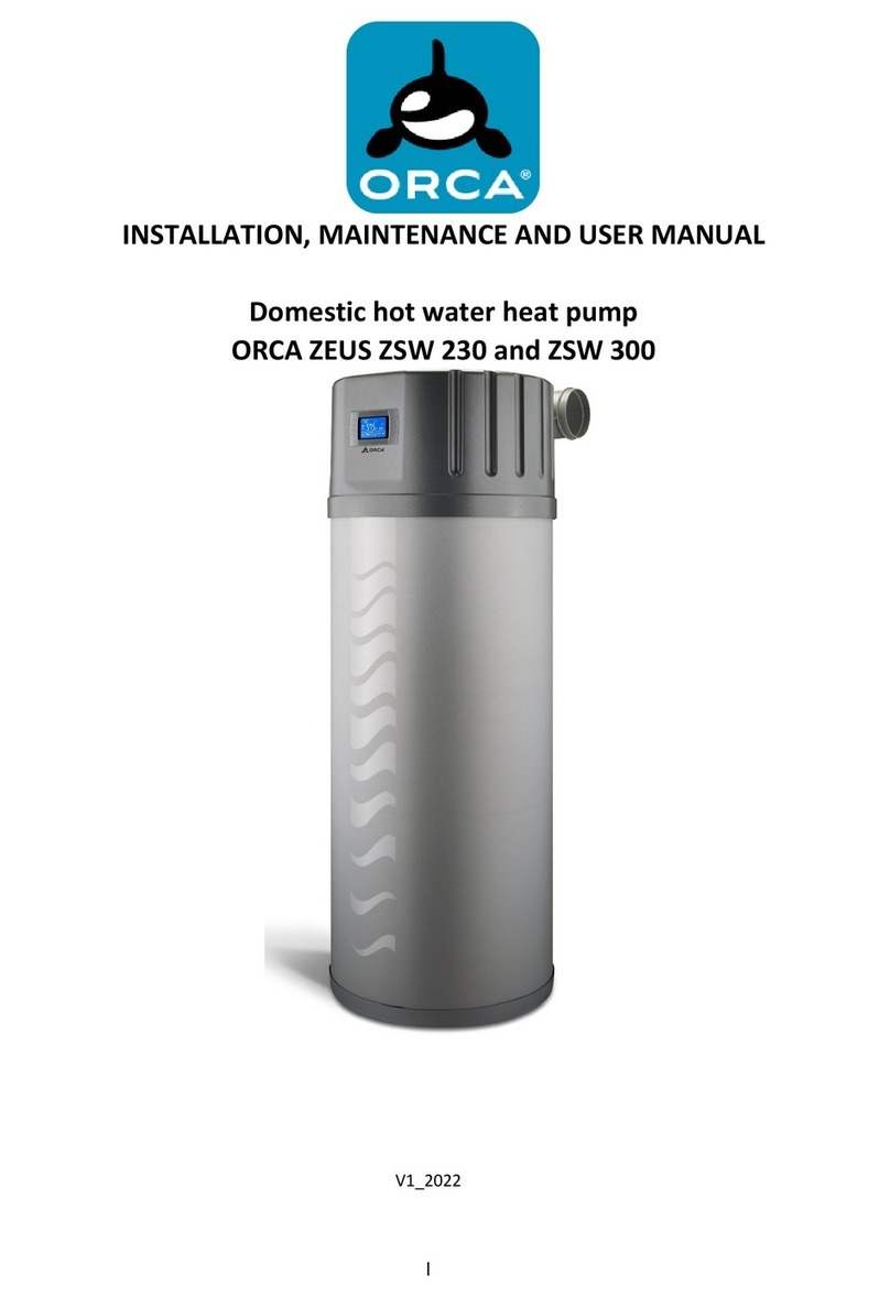
Orca WSW COMPOSITE User manual

Installation and user manuals for domestic hot water
heat pump
ORCA
WSW COMPOSITE
V1_2022

Manuals are made for different series of device. Because of that reason there could be some differences
between real parameters, dimensions or pictures.
We reserve the right to change the technical or any other specifications without notice and without liability.
We do not take responsibility for typographical errors.

CONTENT
1Important warnings________________________________________________ 1
2Purpose of device__________________________________________________ 1
3Unit specifications _________________________________________________ 2
4Transport and depot _______________________________________________ 2
5Instructions for safe maintenance ____________________________________ 3
5.1 Needed supervisions ______________________________________________________________________ 3
6Unit dimensions ___________________________________________________ 4
7Unit installation___________________________________________________ 5
8Water connection _________________________________________________ 6
8.1 Filling and venting heating system ___________________________________________________________ 7
9INSTRUCTIONS FOR USE ____________________________________________ 8
9.1 Function of wire controller _________________________________________________________________ 8
9.2 Operations ______________________________________________________________________________ 9
9.3 Turn ON/OFF the unit ____________________________________________________________________ 10
9.4 Mode selection _________________________________________________________________________ 11
9.5 Time setting ____________________________________________________________________________ 12
9.6 In the vocation mode ____________________________________________________________________ 18
9.7 Electric heater setting ____________________________________________________________________ 19
9.8 FAN MODE SETTING _____________________________________________________________________ 20
9.9 Kejboard locking ________________________________________________________________________ 21
10 TROUBLESHOOTING ______________________________________________ 22
11 ELECTRIC SCHEME ________________________________________________ 23
12 Temperature sensor resistance______________________________________ 24
13 Parameter table__________________________________________________ 25
13.1 Temperature sensor resistance ____________________________________________________________ 28
14 Connection of electric heater or other heat source ______________________ 29
15 Troubleshooting and solutions ______________________________________ 29

1
1Important warnings
-This unit must be well earthed during operation; otherwise serious injuries and also death can occur.
-Power supply must be protected with a safety FI switch (current to switch off max. 0,03A).
-Newer incline the unit for more than 30°from its vertical position.
-Do not install the unit in space with a lot of dust or chemical gasses in the air, the unit can be damaged.
-Do not install the unit in a space where the temperature can fall below 0°C, water in the pipes and unit
can freeze and cause damage to the unit or pipes.
-One way valve and cleaning filter must be installed on the cold water inlet pipe
-On the hot water outlet pipe, installation of a pressure safety valve (max. 0,7MPa) is MANDATORY. The
maximum allowed pressure in the heat pump is 0,3MPa.
-Do not insert fingers of other objects into holes for air inlet and outlet. Rotational parts in the unit can
harm you.
-The unit needs to be installed in a dry space, if it is exposed to direct sun it needs to be protected for it.
-Ensure a clean working environment of the heat pump. Periodically check and, if needed, clean the
working environment of the heat pump. This way, the frequencyof evaporator cleaning will be decreased
and proper and optimum operation of the heat pump will be ensured.
-If the intended installation location of the heat pump is in a room or area, where there is a lot of dust or
ash, possibility of volatile and explosive substances or other undesirable substances leakage, wood or
pellet stove, it is necessary the air intake for the heat pump is made from a different room. Dust and ash
can accumulate on the evaporator and in the interior of the heat pump, which can lead to malfunction
or failure of the heat pump. Leakage of volatile and explosive substances can cause an explosion or fire.
-Do not use or store flammable materials near the unit
-The unit must be connected to power supply protected with the prescribed fuse.
-Only an adult person acquainted with the content of this manual, can operate the heat pump.
-In case of power supply cable damage, smoke, unusual smell from unit or any other abnormality in
operation, immediately disconnect the power supply cable from the supply and contact an authorized
service person.
-The unit can only be used for purposes prescribed by the manufacturer.
-The unit must be replaced and disposed according to local regulations; it contains environment
potentially harmful gasses.
-Water with temperature above 50°C can cause injuries, when set temperature is higher than 50°C be
more careful when children and other users are using hot water.
-During operation it is forbidden to move, clean or repair the unit.
-Do not put any object below or on the unit.
-Unit Installation must be performed by a qualified installer and always in non-electrically supplied
condition.
-There needs to be enough space left around the unit, in case of cleaning and maintenance.
-When connecting the heat pump to the system, it is not recommended to use galvanized transition pieces
or copper pipes in order to prevent corrosion by a galvanic couple. It is advisable to use short flexible
tubes to connect the heat pump to the system. Detailed information about possible faults, their removal
and protection are described in standards SIST EN 12502-1 and SIST EN 806-4.
2Purpose of device
The device is an air-water heat pump that can be connected to a water storage tank with an integrated heat
exchanger. Its primary task is to heat sanitary water –the cooling effect on the surroundings of the device is

2
a side effect. The heat pump is to be set in a sufficiently large and ventilated room with enough high
temperatures (basement, pantry,…) from which it will take the energy for its operation. The heat pump draws
75% of the necessary heat from the air, the rest is provided by electrical power that drives the high-quality
rotary compressor. The sanitary water is heated through a heat exchanger (condenser) integrated in the
water storage tank.
3Unit specifications
MODEL
WSW COMPOSITE
2,5kW
Nominal heating power
kW
2,5
Max. allowed electric heater power
kW
2
Compressor nominal power consumption
kW
0,7
Compressor
typ
Hitachi - rotary
COP (EN255-3) A15 / A20
W/W
3,5 / 4,1
Power supply
f/Hz/V
1/50/230
Minimal fuse capacity
A
16
Refrigerant/quantity
Typ/g
R134a / 1000
Recommended water tank volume
L
400 ~ 500
Minimal surface of heat exchanger
m2
1
Air flow
m3/h
500
Air connection dimensions
mm
150
Maximal length of air ducts
m
10
Unit dimensions
D x W x H
(mm)
550 x 600 x 450
Max. water outlet temperature
°C
55°C
Working range
°C
-3~35
Noise level
dB(A)
48
Water connection dimensions
˝
3/4 –external thread
Max. water pipe length
m
10
Recommended expansion vessel volume
L
3
Unit net weight
kg
59
4Transport and depot
- The device must be protected with a compulsory protective belt during transport.
- IMPORTANT: The allowed temperature during transport and depot is between 10 and 45°C. For short
periods of time (up to 24h), a higher temperature is allowed (up to 55°C).

3
5Instructions for safe maintenance
If all instructions for installation, usage and maintenance are followed, the heat pump will work without
servicing and additional maintenance.
If the heat pump is off for a longer time period (during the winter months), it must be periodically (every
fortnight) turned on and let to operate for some time (30min).
In specific seasons (especially during the winter) and in specific air conditions in the room (temperature,
humidity), where the heat pump is installed, different amounts of condense can result in the condense
container under the evaporator. Sometimes there is a lot of condense, sometimes none, but this does not
mean, that the heat pump is not functioning properly. The quantity of condense water depends on current
relative air humidity in the room and time of operation of the device.
- IMPORTANT: The unit needs to be mounted near to the water storage tank on the wall in horizontal
position. Below the unit must be enough space to connect the water pipes and condensate drain. Above the
unit there must be enough space to connect the air pipes and maintenance
- The unit must be installed on a solid wall with enough strength that during operation it does not
move or amplify vibrations.
- IMPORTANT: when air pipes are connected to the unit to take or blow air to the outside or a space
where the air temperature can drop below 0°C, the heating system must be filled with a mixture of glycol
and water with enough protection against water freezing. If this happens, the unit can be irreparably
damaged.
5.1 Needed supervisions
-Monthly inspection of the flexible pipe for condense water flow,
-Monthly inspection of the non-return valve on the cold water connection –gently push the lever on the
valve until water runs out,
-Every half year check the quality of the supply cable
-Every half year a visual check of the unit and possible leakage
-Yearly check of the installed Mg. Anode and replacement every two years( even earlier if needed)
-Cleaning of the electric heater every 2 years
-Call for regular yearly service

4
6Unit dimensions
Water connections are 3/4" (external thread)
Air duct connections are in diameter 150mm and pipes to connect need to have same or bigger diameter.
Air outlet
air
out
let
Air inlet
air
out
let
Condesate outlet
Electrical connections
Water outlet ¾''
Water inlet ¾''
Upper connections

5
7Unit installation
Min. one elbow is required. Because the inlet and outlet air connections are very close together there is a
possibility of cold air circulation which leads to defrosting.
When attaching the unit on the wall, it is very important that you use properly sized screws that can securely
hold the weight of the unit to prevent its movement during operation. It is also important that the wall where
unit is installed is strong enough to withstand the weight of the unit and does not transfer vibrations.
RECCOMENDATION: do not install the unit on a bordering wall to a space where you stay for a longer period
of time (bedroom, living room,…). There is a possibility that some vibrations can be transferred through the
wall and disturb your well-being.
When the air inlet and outlet are in different spaces, each space needs to
have an opening to the outside or they need to be connected with an
opening surface at least 400mm2 to be able to equalize pressure.

6
8Water connection
Marks:
CWI –cold water inlet
HWO –hot water outlet
TTT –temperature sensor of water outlet
BTT –bottom temperature sensor
F –water outlet (water inlet to water tank heat exchanger)
R –water inlet (water outlet form water tank heat exchanger)
IMPORTANT: The temperature sensor BTT must always be installed higher than the heat exchanger in the
water tank. If it is installed lower, water will be heated to a higher temperature than the set temperature in
the controller settings. In this case, the unit will not work properly.
IMPORTANT: the heat pump has an option to connect an additional electric heater to help the compressor
to heat water in the tank. This electric heater must be installed directly in water tank. In this case, the
temperature sensor TTT must be installed higher than electric heater. If it is installed lower, it can lead to
electric heater damage or even failure of the water system because of boiling water in the tank. Maximum
capacity of the electric heater connected to unit’s controller is 2 kW. The installed electric heater must have
an integrated thermal cut-off protection with maximum allowed temperature 90°C.
On the heating system it is recommended to install an expansion vessel with volume 3L or more.
When air pipes are connected to the unit to take or blow air to the outside or a space where the air
temperature can drop below 0°C, the heating system must be filled with a mixture of glycol and water with
enough protection against water freezing. If the water in the system freezes, the unit or system can be
damaged.
IMPORTANT: Newer connect the unit directly to the water tank without an additional heat exchanger in the
tank itself. The unit is not dimensioned to work with such a high pressure that is in the water supply system
and can be damaged.
Pressure in the heating system needs to be between 0,05 MPa (0,5bar) and 0,3MPa(3bar). During installation
it is also important that the complete heating system is well vented and pipes are not blocked to enable
normal water flow between the unit and heat exchanger in the water tank.

7
To connect the water tank on the water system, consider manuals supplied by water tank manufacturer
On the back side of the unit there is a pipe connection for condensate drain. This connection must be
connected to outlet drainage, because in high water usage and air moisture there can be more than a few
liters of water in one day. This pipe needs to have constant incline at least 1°and must be always clean.
When connecting the heat pump to the system, it is not recommended to use galvanized transition pieces
or copper pipes in order to prevent corrosion by a galvanic couple. It is advisable to use short flexible tubes
to connect the heat pump to the system. Detailed information about possible faults, their removal and
protection are described in standards SIST EN 12502-1 and SIST EN 806-4.
Condensate pipe needs to be checked and cleaned once per month.
The supply socket needs to be at least 1,5m above ground level, to avoid direct spraying of water causing
injuries and damage. The socket needs to be earthed, secured with 16A fuse and FI relay (max. current
0,03A). The cable to the socket must be at least 3x2,5 mm2, and only the heat pump can be connected to
the socket and no other consumers.
8.1 Filling and venting heating system
Under the cover of the unit you can find the fill and safety
valve.
On the fill valve (connection 3/4”) you must connect a water
pipe from water supply system, thenopen the tap and fill valve.
When you open the tap and fill valve, it is important that you
gently turn the red handle on the safety valve a few times, to
remove air from the system. To remove all of the air from the
system, we recommend turning the unit on and off for a few
minutes during filling process 3 times, to start the circulation
pump. During operation, open the safety valve a few times.
When all air is removed from the system, fill water up to the
maximum pressure 0,3MPa (3bar), which is limited with the
safety valve. When max. pressure is reached, close the tap and fill valve, remove the connection pipe and put
on the fill valve safety cover.
If the system is not filled properly or there are air bubbles in the system, the unit will not work with the best
efficiency, it will overheat and in worst case it can be damaged.
When the unit is in constant operation you need to check the pressure in the system at least once per year.
For normal unit operation, the pressure must always higher than 0,05MPA (0,5bar).

8
9INSTRUCTIONS FOR USE
9.1 Function of wire controller
No
Button
Name
Function
1
ON/OFF
Turn on/off the unit.
2
Mode
Switch unit running modes or save setting parameters.
3
Clock
Set the clock or the timer.
4
Electric heater
Turn on/off the electric heater or switch fan modes.
5
Up
Move up or increase parameter values.
6
Down
Move down or decrease parameter values.
Auxiliary display
area
Main display
area

9
9.2 Operations
Status icon
Name
What it means
Heating
Shows that the unit is in heating mode. Compressor is in operation. If
the set temperature is not achieved the electric heater turns on.
Eco, Heating
Shows that the unit is in e co.heating mode. Eco mode is recomended,
if the room temperature is 18°C or more.
Vacation
Shows that the unit is in vacation mode.
Cooling
Shows that the unit is in cooling mode.
Fan
Shows that the fan is on and the speed of the fan.
Electric heater
Shows that the electric heater is on.
Set temperature
acheved
Shows that the water temperature has reached the target
point and the unit shut off automatically.
Parameter
setting
Shows that the water temperature has reached the target
point and the unit shut off automatically.
Temperature
Shows that the temperature is non-adjustable
(measured value).
Timer & ON
Shows that the unit will be turned on by the timer
automatically.
Timer & OFF
Shows that the unit will be turned off by the timer
automatically.
Minute
Shows that the main display area displays the minute.
Second
Shows that the main display area displays the second.
Cetigrade
Shows that the temperature in Main display area or Auxiliary
display area is in ℃.
Faradej
Shows that the temperature in Main display area or Auxiliary
display area is in ℉.

10
Lock
Show that the keyboard is locked.
9.3 Turn ON/OFF the unit
Press and hold for 0.5s in the standby interface of the wire controller to turn on the unit and
at this time the main display area shows the water outlet temperature.
Press and hold for 0,5s in the running interface of the wire controller to turn off the unit an at
this time the main display area shows OFF.
Note. The ON/OFF button can only be used to turn on/off the unit in standby or running interface of
the wire controller.
Heating mode
Standby
interface
Press and hold for 0,5s
Outlet water temperature
Inlet water
temperature
Running interface

11
9.4 Mode selection
Press , to select the mode from Heating, Eco heating, Intelligent, Vacation in the stanbay or
funning interface.
In teh standby or running interface press or ,once to check the target temperature of the
outlet water. Press or , again to change the target temperature. After making the changes
to the parameter, press to confirm or to cancel the changes, then return to the previous
interface. If no operations are performed on the kaypad for 0,5s, the controller exits the parameter
modification menu by time out and the changes are confirmed,.
Example: Change the target temperature form 50 to 55,5 when the actual outlet water temperature is
18 0C.
Time
Outlet water temperature
Heating mode
Eco heating mode
Press
Press
Press
Vacation mode
Date
Intelligent mode

12
9.5 Time setting
In the standby or running interface, do as folows to set the time when in heating mode. When press
once, the time parameter will flash. When press ,again, the hour parameter will flash then
press or , to change it. After making the changes to the parameter, press , to confirm,
then change the minute parameter as well as the date parameter in the same way.
If no operations are performed on the kaypad to 10s, the controller exits the parameter modification
menu by timeout and the changes ar comfirmed.
Note. Set the data in the same way when in vacation mode.
Example: Change the time and date from 18:30 on Avgust 4th to 17:40 on September 8th.

13

14
In the the heating mode, two running period scan be set
Press nad hold for 2s to enter into the timer setting interface..
Running period 1. The symbol ON 1 on the right side of the interface and the timenparameter flash at this time.
Press agin and the hour parameter flashes. Set the time according to the 2.6 and conforim. Then OFF 1
and the time parameter flash. Set the time following the previous steps.
Running period 2:After Running Period 1 is set, the controller will enter into the Running period 2 setting
interface. Set the start –up and shut –down time in the same way as Running period 1.
Press to canacel any modifications during the setting.
Press and hold for 2s twice to set the OFF 1 time directly or press when the unit is already
running.
Press cancel nthe setting when the hour parameter is flashing.

15
Example:Running period 1. 8:00 –10:00; Runing period 2: 16:30-22:00

16

17
If you want to cancel the timer setting, follow this below
Table of contents
Other Orca Heat Pump manuals
Popular Heat Pump manuals by other brands

Trane
Trane 4TTX6 Installer's guide

ECOGENICA
ECOGENICA EG-330FR manual

Viessmann
Viessmann VITOCAL 300-G PRO Type BW 2150 Installation and service instructions

Mitsubishi Electric
Mitsubishi Electric SLZ-KF09 Operation manual

Amana
Amana PACKAGE HEAT PUMP owner's manual

Johnson Controls
Johnson Controls YORK BCHO-74G technical information

Unitary products group
Unitary products group GY8S*DH installation manual

TESY
TESY HPWH 2.1 260 U02 S Instruction for installation and maintenance

Dimplex
Dimplex LA 16 MI operating instructions

Carrier
Carrier Infinity 25VNA4 owner's manual

Sanyo
Sanyo ECO-i APR-RZP680BAB datasheet

Hayward
Hayward HeatRelax Installation and instruction manual