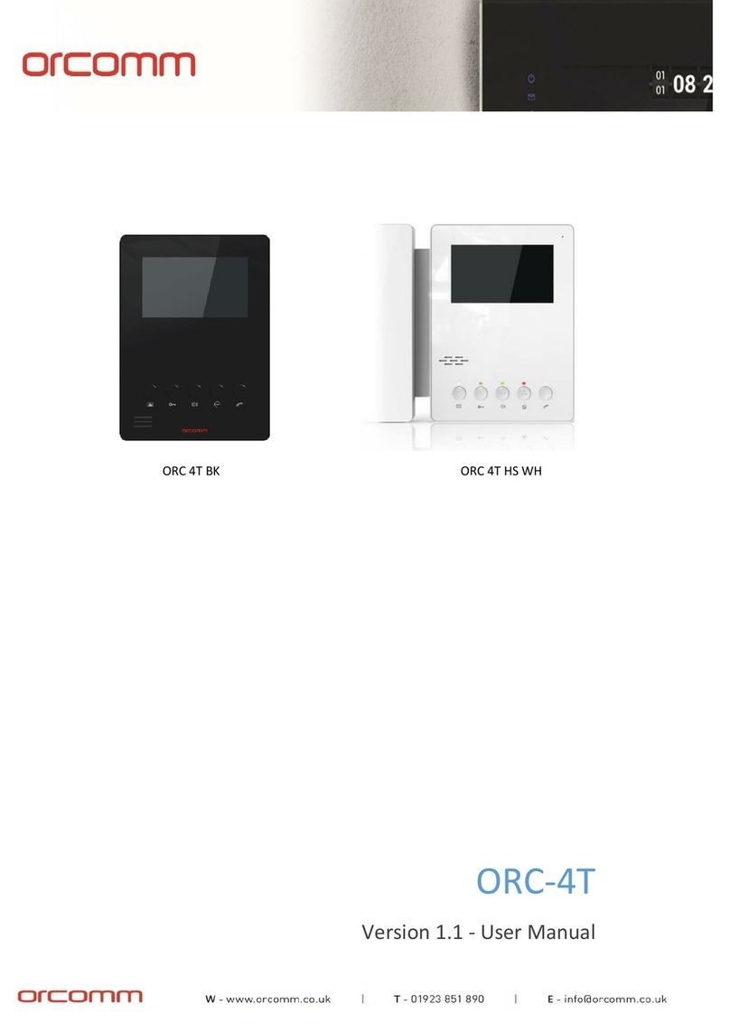
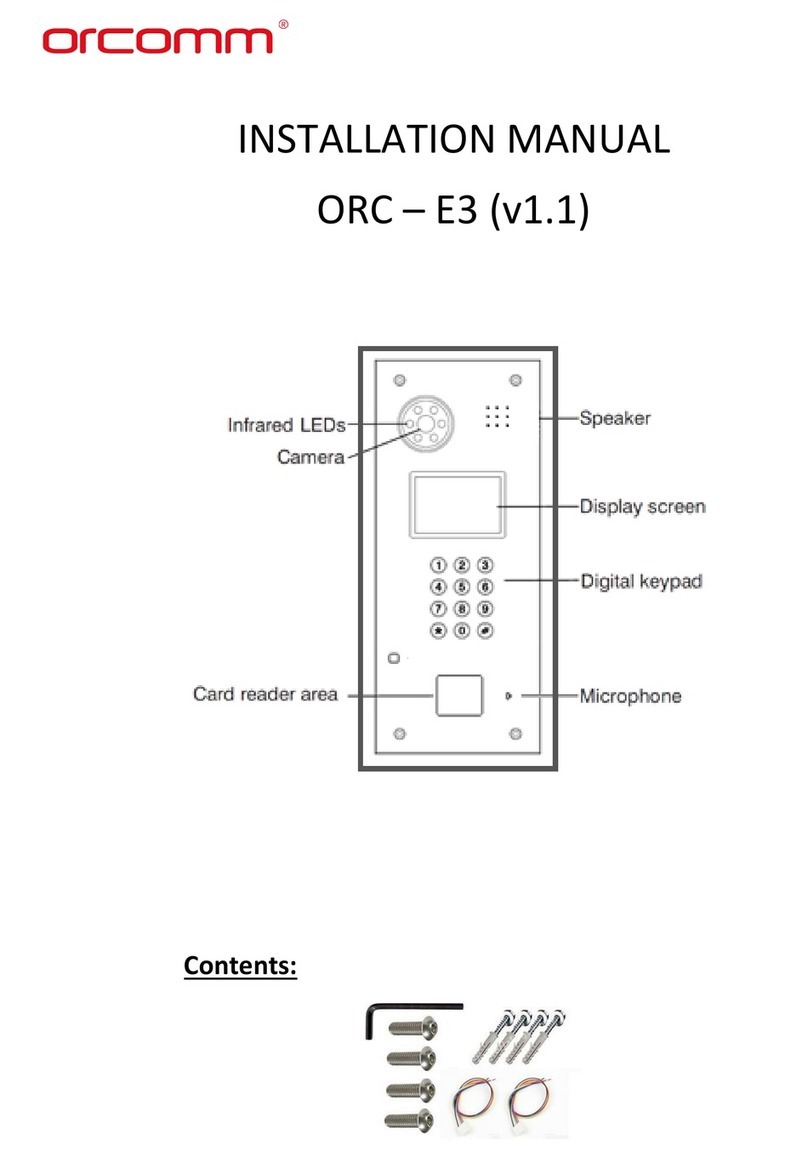
Orcomm ORC-E3 User manual

ORC-E3
Version 1.0 - Installation and User Manual

1
Please follow this user manual for the correct installation and testing, if there is any doubt please call
our tech-support and customer centre.
The illustrations shown here are only used for reference, if there is any difference please take the
actual product as standard product.
Please ensure that you seek advice and correct IP settings before connecting any equipment to an IP
network to ensure there is conflicts or incompatibilities.
Contents
Basic Operation:......................................................................................................................................3
Management Centre Calling: ..................................................................................................................3
Coded access unlocking: .........................................................................................................................3
Unlocking by access password............................................................................................................3
Unlocking by IC/ID card....................................................................................................................... 3
Basic Settings: .........................................................................................................................................4
Application .......................................................................................................................................... 4
Reg. card ............................................................................................................................................. 5
Unlock ................................................................................................................................................. 5
Delay ................................................................................................................................................... 5
Password............................................................................................................................................. 6
Unlock PSW.........................................................................................................................................6
Ring tone.............................................................................................................................................6
Language ............................................................................................................................................. 7
Panel Mode .........................................................................................................................................7
System Setup ..........................................................................................................................................8
Device No ............................................................................................................................................8
Address No..........................................................................................................................................8
IP .........................................................................................................................................................9
Mask....................................................................................................................................................9
Gateway ..............................................................................................................................................9
Server ................................................................................................................................................10
Default...............................................................................................................................................10
Reboot............................................................................................................................................... 10
System Information ..........................................................................................................................11
About Us ........................................................................................................................................... 11
Web Settings.........................................................................................................................................11

2
LAN setting:.......................................................................................................................................12
Access setting:...................................................................................................................................14
VOIP: .................................................................................................................................................15
Forward: (Call transfer):.................................................................................................................... 16
ExModule: .........................................................................................................................................17
Advanced: .........................................................................................................................................17
Default: .............................................................................................................................................18
Logout: ..............................................................................................................................................18
Maintenance of devices........................................................................................................................19
Please Note ...........................................................................................................................................19

3
Basic Operation:
When programmed as outdoor panel, input floor and room number (the digit is 3 at least), then
press “✓”to confirm. If you forget to press “✓”to confirm the input, it will call after 2 seconds
automatically.
When the room number is <2 digits, you should press ““✓”” key to confirm the calling. When
programmed as wall station, input Building No. + “✓”+Unit No. + “✓”+room No.+ “✓”button to call.
If the number is correct, the indoor monitor rings. If the number is incorrect or the indoor monitor
does not exist, the outdoor panel will display “Failure”. After 2 seconds, it will return to standby
mode.
If the indoor monitor is busy, the outdoor panel will display “Busy”, then auto return to standby
mode.
During a call, press “X” button on the outdoor panel, to hang up the call.
Management Centre Calling:
In standby mode, input (4 digits) “0000", then press “✓”key to call management centre. If success,
the outdoor panel will display “Calling”, the management centre rings.
If the number is incorrect or the management centre does not exist, the outdoor panel will display
“Failure”. After 2 second, it will return to standby mode.
If the management centre is busy, the outdoor panel will display “Busy”, then auto return to standby
mode.
During a call, press “X” button on the outdoor panel, to hang up the call.
Coded access unlocking:
Unlocking by access password
Press “✓”key, enter the access password (The default is 0000). Then press “✓”key to confirm. If the
password is correct, the door will be unlocked; if not, it will display “Password Err” on the display.
Unlocking by IC/ID card
Put the registered IC/ID card on card reader area of the outdoor panel. If successful, the door will be
unlocked.

4
Basic Settings:
Press (“✓”) key twice, the LCD screen will show as following:
Enter the system password (Factory default one is 123456) to enter the main menu
In Set menu, you can set following items.
Application
Press “✓”key to enter the following setting screen:
Press “2” key to page up, press “8” key to page down; press “✓”key to confirm; press “X” key to
return.

5
Reg. card
Press “✓”key to enter the following setting screen:
When in this mode enter the room number that you want to assign access card to. Touch ID card to
the panel reader. Press “✓”to confirm.
Unlock
Press “✓”key to enter the following setting screen:
Input the value (1-9 corresponding 1-9 seconds). Then press “✓”key to confirm. it will show you
“Success” on the display.
For example, if you select 8, it indicates that the unlocking timeout is 8 seconds. When the user
unlocks the door, it will be closed after 8 seconds automatically.
Delay
Press “✓”key to enter the following setting screen:

6
Input the value (0-9 corresponding 0-9 seconds). Then press “✓”key to confirm. it will show you
“Success” on the display.
For example, if press 5, it indicates that the delay unlocking time is 5 seconds. When the user
unlocks the door, it will be unlocked after the 5 second delay has lapsed.
Password
Press “✓”key to enter the following setting screen:
Input new system password (1-6 digits), press “✓”key, it will show you “Success” on the display.
Note: Don’t forget the password, otherwise you have to return the device to factory defaults to gain
access.
Unlock PSW
Press “✓”key to enter the following setting screen:
Input new unlock password (1-6 digits), press “✓”key, it will show you “Success” on the display.
The outdoor panel can store 8 different unlock passwords.
Ring tone
You will hear a ring-back tone when calling others, four kinds of rings for option, press “✓”key to
enter the following setting screen:

7
Input digit from 1-4 to select different ring tone. Then press “✓”button to confirm the, it will show
you “Success” on the display.
Language
Press “✓”key to enter the following setting screen:
Input digit “1” for simplified Chinese, “2” for English, “3” for Russian, “4” for Traditional Chinese, “5”
for Turkish, “6” for Polish, then press “✓”key to confirm. After that, the system will restart and
switch to the language you have selected.
Panel Mode
Press “✓”key to enter the following setting screen:
This device can be used as the outdoor panel or wall station by setting the panel mode.
Input “0", this device is used as unit (outdoor panel for one building), and input “1”, it is used as wall
station (outdoor panel for global access). Then press “✓”key to confirm, it will show you “Success”
on the display.

8
System Setup
In System Setting menu, you can do the following settings:
Device No
You can install 99 outdoor panels in one building. If you want to install more than one outdoor
panel in one building, you need to set your outdoor panel into two type: main & sub outdoor panel.
Press “✓”key to enter the following setting screen:
Input digits between 1 to 99 to set the outdoor panel as main or sub. When you input digit “1”, the
outdoor panel is set to be the main outdoor station; when you input digit between 2 to 99, the
outdoor panel is set to be the sub outdoor panel. After setting the main & sub outdoor panel, the
indoor monitor can switch to monitor the main & sub outdoor panel.
Address No
Press “✓”key to enter the following setting screen:
When the device is used as outdoor panel, input (3 digits) building No. + (2 digits) unit No., then
press “✓” key to confirm, it will show you “Success” on the display; when the device is used as wall
station, the item will be invalid.

9
IP
Press “✓”key to enter the following setting screen:
The IP address is unique in the same LAN network. If the total quantity of the IP address in one
community or project is ≤255, you only need to revise last 3 digits (0~255); if the total quantity of
the IP address is >255, you need to revise last 6 digits (0~255; 0~255), then press “✓” key to
confirm, it will show you “Success” on the display.
Remark: the IP address of all the outdoor stations must be in the same segment.
Mask
Press “✓”key to enter the following setting screen:
The default Mask address is 255.255.255.0. Normally, it is unnecessary to revise.
Gateway
Press “✓”key to enter the following setting screen:

10
The default is 192.168.68.1. The setting of gateway address should be accessible to the IP address
given to the device. Just to confirm the Gateway address is also in the same network segment.
Server
Press “✓”key to enter the following setting screen:
Enter the address of management server if one is being used on the system.
Default
Press “✓”key to enter the following setting screen:
Input “1" to indicate that confirm to recover, input “0" to indicate that cancel it. Press “✓”button to
confirm.
Reboot
Press “✓”key to enter the following setting screen:
Input “1" to indicate that confirm to restart, input “0" to indicate that cancel it. Press “✓”button, the
system will restart.

11
System Information
Press “✓”key to enter the following setting screen:
Press “2”up or “8” down key to check the relevant information of system.
NET: network connectivity status. When the system display “ERR”, the network is disconnected;
when it displays “Ok”, the network is connected.
SIP: registration status of SIP server. When the system displays “ERR”, the SIP server is unregistered;
when it displays “Ok”, the SIP server is registered.
About Us
Press “✓”key to enter the following setting screen:
You can see the relevant information of system software version.
Web Settings

12
Connect outdoor panel and PC in the network switch and make them in the same LAN. Input IP
address of outdoor panel in the web browser of PC (For best results please use Internet explorer),
then input the user name and password (the default name is admin, the password is 123456) to
enter into the following interface:
LAN setting:
Click “LAN” icon on the interface to enter into the following interface:
IP: IP address should be unique in the same LAN.

13
Mask: the default Mask is 255.255.255.0.
Gateway: it depends on IP address.
DNS: it depends on LAN.
Server IP: it is the same as the IP address of management PC.
NTP: it refers to network time protocol source address.
Usually, the communication among management centre, indoor monitor and outdoor panel will
be available in the same LAN; if they are not in the same LAN, you need to set SIP server to
support the communication.
Click “Submit” icon to confirm settings.
1. Device setting:
Click “Device” icon on the interface to enter into the following interface:
The settings of building No and Unit No. should be the same as that of corresponding outdoor
panel No.
It is a unique number for the outdoor panel. You can have max.9 outdoor panels in one house,
and you need to distinguish their numbers from 1 to 9.
Sys password: you can change the login password as you like (the default password is 123456).
Panel mode: unit panel, wall panel and personal panel for option.
Unit panel: Used in one unit, calls residents in the unit and management centre; Wall panel:
Used in the entrance of community, call all outdoor panel in the community and management
centre;
Person panel: It is reserved.
You can choose different ring back tone and language, also adjust the ring back volume.

14
Click “Submit” icon to confirm settings.
Access setting:
Click “Access” icon on the interface to enter into the following interface:
Unlock timeout: After 1-9 seconds, the door is closed.
Unlock delay: The door lock is unlocked after 0~9 seconds.
Elev refer: It is reserved.
Security ON/OFF: It is reserved.
Unlock password: It is used for unlocking the door, the default is 0000, you can set 8 groups of
password.
Click “Submit” icon to confirm settings.
Card registration:
1. Register admin card: input “0” in the frame, and confirm the setting. Touch the admin card to
the card reader, and the outdoor panel will sound a tone. It indicates that admin card
registration is successful.
2. Register the unlock cards: swipe admin card firstly, then swipe the new unlock card within 10
seconds. It will sound a tone and indicate the unlock card is successfully registered. If exceeds
the time, it will be delayed for 10 seconds.
Note: the admin card cannot be regarded as unlock card and open the door.

15
VOIP:
Click “VOIP” icon on the interface to enter into the following interface:
Input the relevant information if you have a SIP server or network/system engineer.
Proxy: Enter the IP address of the SIP register server.
Realm: Enter the Realm name or IP address. If unknown use same as proxy server.
Outbound: If an outbound SIP server is being used enter the address hear.
STUN IP: STUN server Address.
STUN Port: STUN server port number.
User: SIP Username given by proxy server.
Password: SIP account password given by proxy server.
Bitrate: Select bitrate for bandwidth control (Recommend to leave as default)
Host2ID: Enabled use a combination of building, unit, flat and device number to make up SIP
user part in SIP From message.
Disabled uses the User as the SIP user part in the SIP from address when setting up
call. (Recommended Setting)

16
Forward: (Call transfer):
Click “Forward” icon on the interface to enter into the following interface:
1. Make the call to another SIP extension (with SIP server)
For example, you want to call SIP extension 100, you can set it like this:
So, when you press 100 on the outdoor panel, it will call extension 100 via the SIP server.

17
2. Make the SIP call to another SIP device (Without SIP server, Direct SIP calling)
For example, you want to call a SIP device with IP address 192.168.15.100, you can set it like
this:
SIP:1@192.168.15.100 (Note: “1” has no indication of the number being called. “1” can be any
factious number)
When you press 100 on the outdoor panel, it will call the SIP device with IP address
192.168.15.100.
3. Forward to multiple devices (One by One or All at once)
If you want to make several devices ring together or ring one by one, you can set like this:
If you select Forward type as “one by one“ in the “Device“ settings ,when you dial 100 on the
outdoor panel, these two devices will ring one after another.
If you select Forward type as “All at once” in the “Device” settings, when you dial 100 on the
outdoor panel, these two devices will ring together.
NOTE: The number of forwarded devices is unlimited.
ExModule:
It is reserved.
Advanced:
It is reserved.

18
Default:
Click “Default” icon on the interface to enter into the following interface:
Click “Submit” icon, now all the registered cards are deleted (admin card cannot be deleted).
To back up all the setting on the outdoor panel;
Click “Click to backup settings” icon, the system will back up the current settings. Save the
downloaded file for future restores or changes.
To restore all the setting from a backup file;
Click “Restore Backup” icon to select the backup file to restore the settings.
Logout:
Click “Logout” icon on the interface to enter into the following interface:
Click “Submit” icon to logout the system.

19
Maintenance of devices
•Keep the surface of the screen clean using a soft dry cloth only.
•Do not use benzene, thinner or organic solvents such as gasoline to clean, these solvents
may cause damage to product.
Please Note
•Read the instructions in this handbook carefully. Be sure to keep it for future reference.
•Be sure to use only the power adapter and that your power source matches the rating listed
for it. If you are not sure, check with your dealer or with your local power company.
•Avoid strong hits or shocks. Do not use the power adapter if it is has received any hard
knocks or looks damaged in any way; immediately contact an authorised service centre.
•Don’t clean the surface with chemicals but with soft and clean dry cloth.
•Don’t press several buttons at the same time.
•Don’t disassemble the machine without authorization, if the need for fault repair, please
contact the distributors or the company’s tech-supporting department.
Other manuals for ORC-E3
1
Table of contents
Other Orcomm Intercom System manuals