Oregon Scientific ESM100 User manual

1
EN
Mini Wireless Energy Manager
Model: ESM100 / ESM100U
USER MANUAL
CONTENTS
Introduction .............................................................. 2
Overview ................................................................... 2
Main unit – Front view .......................................... 2
Main unit – Back view .......................................... 3
Remote transmitter ............................................... 3
Sensor clamp ........................................................ 4
Household power cables and phase ..................... 4
Getting started ........................................................ 4
Locate live outgoing supply cable ......................... 4
Sensor set up. ....................................................... 5
Transmitter set up ................................................ 6
Main unit set up .................................................... 7
Sensor data transmission ..................................... 7
Understanding electricity ....................................... 7
Display modes ......................................................... 8
Cost rate ................................................................... 8
Power save ............................................................... 8
Clear records ........................................................... 9
Reset ......................................................................... 9
Troubleshooting ...................................................... 9
Specifications ......................................................... 9
Precautions ............................................................ 10
About Oregon Scientific ........................................11
EU-Declaration of conformity ...............................11

2
EN
INTRODUCTION
Thank you for selecting the Oregon Scientific™ Mini
Wireless Energy Manager (ESM100 / ESM100U).
The Mini Wireless Energy Manager embodies our
commitment to environmental concerns. Aware of
threats facing the world we live in, Oregon Scientific™
has combined technological know-how, practicality
and style to create this line of products that can help
you reduce your carbon footprint.
With this measurement category II product, you can
view your consumption in real time. By being made
aware of your consumption, you can take practical
steps to reduce it. Your continued effort will be reflected
by the monitor in meaningful terms - estimated costs /
consumption go down over time.
Our aim is to make products that provide practical
solutions while enabling you and us to fulfill our
environmental responsibility. Together we can improve
the world we live in.
Please observe the following warning and safety
precaution guidelines when setting up and using this
product.
NOTE Please keep this manual handy as you use
your new product. It contains practical step-by-step
instructions, as well as technical specifications and
warnings you should know about.
If the equipment is used in a manner not specified in
this manual, the protection provided by the equipment
may be impaired.
OVERVIEW
MAIN UNIT – FRONT VIEW
1
2
3
4
5
6
7
8
1. ENERGY: indicates energy consumption is
displayed
2. COST: indicates cost of energy consumed is
displayed
3. Real time cost / energy consumption
4. Currency unit
5. REMOTE / MAIN: remote transmitter
batteries low / main unit batteries low

3
EN
6. PWR SAVE: power save function is activated
7. Cost / energy consumption measurement units
(KW, PENCE / CENTS per HOUR, PENCE/CENTS
per KWH, KWH, PENCE, CENTS)
8. Accumulated cost / energy consumption (since last
reset)
MAIN UNIT - BACK VIEW
1
2
3
4
5
6
7
8
1. Wall mount hole
2. Magnets for mounting
3. SET: enter cost rate setting mode; confirm settings
4. UP: toggle between displays (Cost / Energy);
initiate remote transmitter search; increase cost
rate value
5. DOWN: toggle between displays (Cost / Energy);
activate / deactivate power save function; decrease
cost rate value
6. RESET: resets the unit and clears accumulated
memory; initiate remote transmitter search
7. Battery compartment
8. Collapsible table stand
REMOTE TRANSMITTER
1
2
3
4
5
6
1. LED status indicator: flashes when searching
2. Sensor cable sockets
3. Wall mount hole

4
EN
4. Battery compartment
5. RESET: resets the unit to default settings
6. CHECK: forces transmission every 2 seconds (for
a period of 30 seconds) to attempt link with main
unit
SENSOR CLAMP
Model CT100
(Europe / UK)
Model CT110
(USA, Canada & other
countries)
Sensor for :
• 220V to 250V AC
• cable size up to
10mm dia &/or 70
amps RMS)
Sensor for:
• 120V AC + Industry
• cable size up to 16mm dia
&/ or 200 amps RMS)
2
3
1
1
2
3
1. Electrical wire hole
2. Plastic tabs
3. Sensor transmitter cable
Optional sensor clamps such as those listed below can
be purchased separately. For more information, please
contact your local retailer.*
• Model CT100
• Model CT110
* Features and accessories will not be available in all
countries.
HOUSEHOLD POWER CABLES AND PHASE
Electricity is generally supplied using single-phase and
three-phase systems.
UK: Most homes in the UK use single-phase supplies.
In single-phase supplies, the current flows to and from
your household appliances using a neutral and live
wire. The neutral wire has a voltage close to zero while
the live wire carries a voltage from 120 to 240 volts.
The difference between these two wires makes the
current flow through your appliances.
Europe: Most homes in Europe use three-phase
supplies.In three-phase supplies, current flows to and
from a device through a group of three wires, each one
carrying a fluctuating phase. The three wires, therefore,
each need an individual current sensor which can be
purchased separately.
GETTING STARTED
LOCATE LIVE OUTGOING SUPPLY CABLE
The sensor clamp should be fitted over the insulated
live wire. It is recommended that you fit it over the
(outgoing) wire which comes out of the electricity meter
located in the meter box.

5
EN
This product uses Type C current sensor, do not
apply around or remove from HAZARDOUS LIVE
conductors.
Under no circumstances should any force or undue
pressure be applied to any wiring or connections.
WARNING Care must be taken at all times to avoid
touching or coming into contact with any un-insulated
wires or contacts.
If any difficulty with installation is experienced at all, the
advice of a licensed electrician should be sought.
OUTGOING
SUPPLY
SENSOR SET UP
WARNING It is recommended for current sensor
clamp(s) to be installed by a licensed electrician.
Switch off power from the mains before attaching and
detaching sensor(s).
1. Using thumb and finger, press inwards on plastic
tabs located on either side of the sensor clamp to
release top part.
2. Lift the top of the sensor away.
2
1
3. Place the main household active or live wire
(outgoing) into the electrical wire hole.
NOTE Do not pull or bend the wires. Ease the wire into
position so you can close the sensor clamp securely
around the wire.
4. Replace the top of the sensor clamp and push
down to secure.
5. Plug the sensor transmitter cable into any of the
cable sockets.

6
EN
4
3
5
NOTE For three-phase system, attach a sensor
clamp to each live wire.
• When attaching the sensor clamp, ensure each
sensor clamp is attached to a different wire
otherwise an incorrect reading may result.
• Then plug all sensor clamp cables into the remote
transmitter. Up to three sensor clamps can be
plugged into the remote transmitter.
WARNING
• The signal wiring (approx. 1 volt, 1 milliamp) on
the sensor clamp is double insulated, suitable for
installation in domestic power supply meter box.
When passing through an enclosure opening, the
wiring should be protected from sharp edges by
fixed bushes.
• Do not use the unit if it is damaged or its safety is
impaired.
TRANSMITTER SET UP
1. Slide open the battery compartment cover.
2. Insert the batteries, matching the polarities (+ / -).
3. Press RESET after each battery change.
4. Press and hold CHECK until LED light flashes.
5. Close the battery door.
6. Mount the transmitter onto an affixed screw.
NOTE Install battery in the transmitter before the main
unit.
For best results:
• Place the sensor within 30 m (100 ft) of the main
unit.
• Place the sensor out of direct sunlight and
moisture.
• Position the sensor so that it faces the main (indoor)
unit, minimizing obstructions such as doors, walls
and furniture.

7
EN
TIP The transmission range may vary depending on
many factors. You may need to experiment with various
locations to get the best results.
MAIN UNIT SET UP
1. Slide open the battery compartment cover.
2. Insert the batteries, matching the polarities (+ / -).
3. Press RESET after each battery change.
4. Close the battery door.
SENSOR DATA TRANSMISSION
If main unit does not display data or after each
transmitter battery change:
1. Press and hold CHECK (located in the transmitter)
until LED light flashes. Transmitter will check for
and transmit data to the main unit every 2 seconds
for 30 seconds.
2. Press and hold UP on the main unit to search for
signal from transmitter.
UNDERSTANDING ELECTRICITY
Voltage
(volts)
Electrical potential. Fixed at 220V-
250V or 120V depending on region.
X
Current
(amps)
Amount of electricity flowing through,
e.g., a wire. (The sensor measures this
to determine watt)
=
Power
(watts)
Amount of energy being transferred.
(KW = 1000W). This type of data is
displayed on the top line of Energy
mode.
KWh is a measure of consumption. Kilowatt hour
represents the use of 1000W of electricity for 1 whole
hour, which is equivalent to ten x 100W light bulbs
operating at the same time for 1 hour.
Once cost rate of electricity has been inputted, the
monitor can arrive at an estimated cost.
NOTE This product is for educational purposes only.
Its aim is to aid understanding of the cost of operating
electrical appliances in the home. It does not replace
your accurate electricity revenue meter.

8
EN
DISPLAY MODES
There are 2 display modes to choose from:
COST
UP / DOWN
Real time cost
of electricity
per hour
Accumulated
cost since last
reset
ENERGY Real time
power (KW)
Accumulated
energy (KWh)
consumed
since last reset
COST RATE
To determine the approximate cost of electricity
consumption, input the cost per KWh.
To set cost rate:
1. Press and hold SET.
2. Press UP / DOWN to change values of the setting.
3. Press SET to confirm and move to the next digit.
NOTE Each utility company sets a different tariff for
electricity consumption. This rate can usually be found
on the electricity bill.
TIP Certain utility companies use a tiered cost of
electricity, whereby the rate increases after consumption
exceeds a specified amount. It is recommended that
an average value is entered as the cost rate.
I.e., Total usage is 1000KWh (500 + 500) which can
be separated as:
500 KWh at 15p = £75
500 KWh at 10p = £50
Then, £125 / 1000KWh = 12.5p
Similarly, some utility companies use different tariffs for
usage at different times of the day. It is recommended
that an average value is entered as the cost rate.
I.e., Total usage is 3000KWh (1000KWh for day rate +
2000 for night rate) which can be separated as:
1000 KWh at 15p = £150
2000 KWh at 5p = £100
Then, £250 / 3000 KWh = 8.3p
POWER SAVE
By decreasing the frequency data is received from
every 6 seconds to every 60 seconds, battery life is
extended.
To activate power save function:
• Press and hold DOWN.
PWR SAVE indicates power save function is activated.

9
EN
CLEAR RECORDS
NOTE When total cost reaches 999.99 or total
energy reaches 999.99KWh, digits will flash to indicate
maximum has been reached and the need to clear
records.
To clear records of TOTAL data (Cost / Energy):
• Press and hold UP and DOWN simultaneously.
RESET
Press RESET to return to the default settings.
TROUBLESHOOTING
PROBLEM SYMPTOM REMEDY
Strange
readings
Strange
readings
Set cost rate setting.
Check appliances are
not malfunctioning
(turned off by itself) as
this could be shown
as a sudden drop in
electricity usage.
High
readings
Check appliances
have been switched
off if not in use.
“- - - -“
displayed
Not
synchronised
Press and hold
CHECK on remote
transmitter.
Then, press and hold
UP on the main unit.
If still unsuccessful,
press RESET on
transmitter and main
unit.
“0.00”
displayed
Problem with
the sensor
Check sensor clamp
has been properly
fitted and closed.
Possible damage in
the sensor clamp.
Replace clamp with
new one.
SPECIFICATIONS
MAIN UNIT
Dimensions
(L x W x H)
66 x 27 x 85 mm
(2.6 x 1.1 x 3.3 inches)
Weight 80 g ( 2.8 oz) without battery
Signal frequency 433 MHz
Transmission
range
30 meters (100 feet)
unobstructed
Information update Approximately every 6 seconds
(EU) / 12 seconds (US / Canada)

10
EN
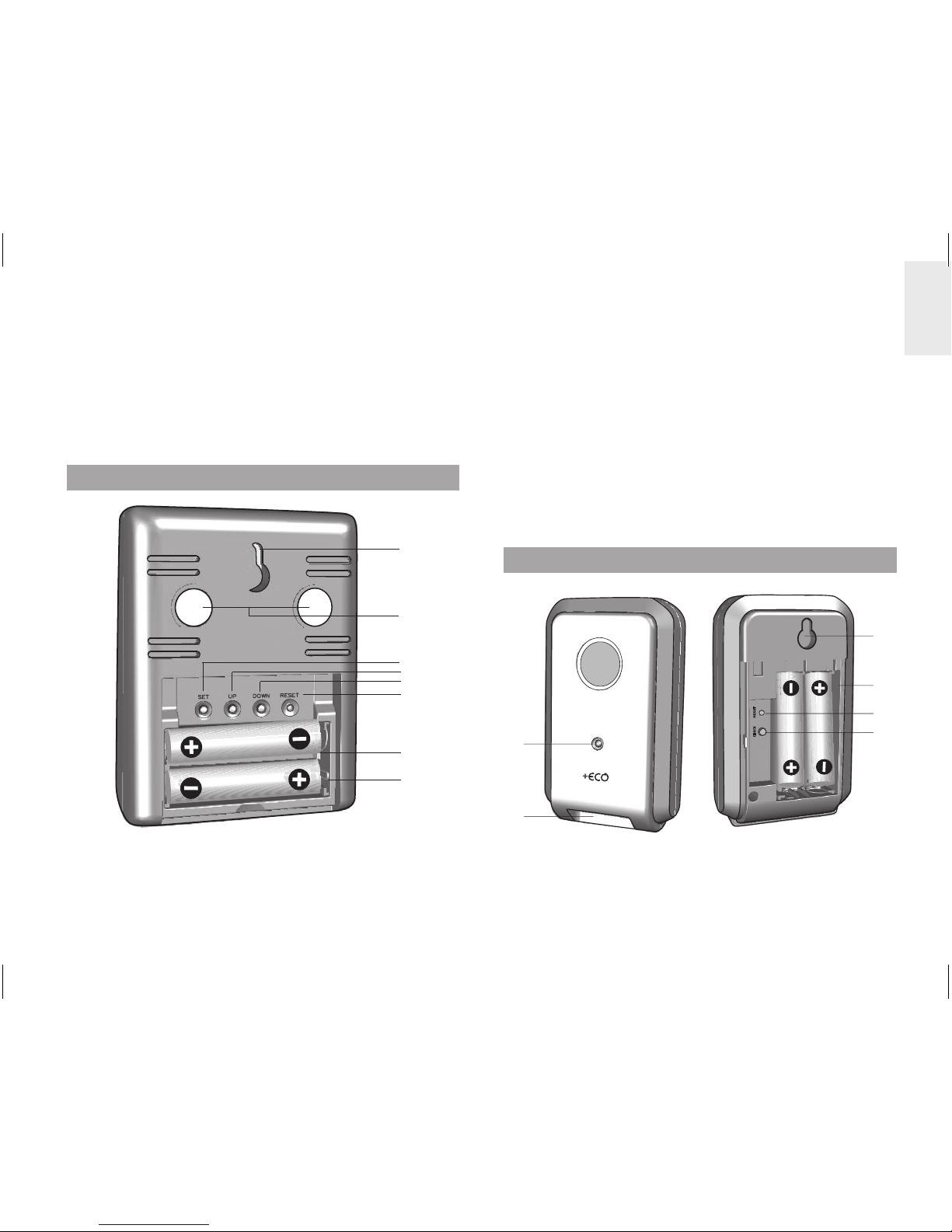
Power 2 x UM-4 (AAA) 1.5V batteries
REMOTE TRANSMITTER
Dimensions
(L x W x H)
59 x 28 x 97 mm
(2.3 x 1.1 x 3.8 inches)
Weight 60 g (2.1 oz) without battery
Power 2 x UM-3 (AA) 1.5V batteries
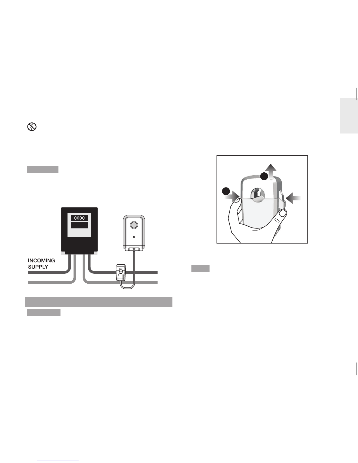
SENSOR CLAMP
CT100
Dimensions
(L x W x H)
40 x 30 x 54 mm
(1.6 x 1.2 x 2.1 inches)
Weight 62 g (2.2 oz)
CT110
Dimensions
(L x W x H)
53 x 40 x 76 mm
(2.1 x 1.6 x 3.0 inches)
Weight 186 g (6.6 oz)
PRECAUTIONS
• Do not subject the unit to excessive force, shock,
dust, temperature or humidity.
• Do not cover the ventilation holes with any items
such as newspapers, curtains etc.
• Do not immerse the unit in water. If you spill liquid
over it, dry it immediately with a soft, lint-free cloth.
• Do not clean the unit with abrasive or corrosive
materials.
• Do not tamper with the unit ’s internal components.
This invalidates the warranty.
• Only use fresh batteries. Do not mix new and old
batteries.
• Images shown in this manual may differ from the
actual display.
• When disposing of this product, ensure it is
collected separately for special treatment and not
as normal household waste.
• Placement of this product on certain types of
wood may result in damage to its finish for which
Oregon Scientific will not be responsible. Consult
the furniture manufacturer's care instructions for
information.
• The contents of this manual may not be reproduced
without the permission of the manufacturer.
• Do not dispose old batteries as unsorted municipal
waste. Collection of such waste separately for
special treatment is necessary.
• Please note that some units are equipped with a
battery safety strip. Remove the strip from the
battery compartment before first use.
NOTE The technical specifications for this product
and the contents of the user manual are subject to
change without notice.
NOTE Features and accessories will not be available
in all countries. For more information, please contact
your local retailer.

11
EN
ABOUT OREGON SCIENTIFIC
Visit our website (www.oregonscientific.com) to learn
more about Oregon Scientific products.
If you’re in the US and would like to contact our
Customer Care department directly, please visit:
www2.oregonscientific.com/service/support.asp
For international inquiries, please visit:
www2.oregonscientific.com/about/international.asp
EU-DECLARATION OF CONFORMITY
Hereby, Oregon Scientific, declares that this
Mini Wireless Energy Manager (model: ESM100
/ ESM100U) is in compliance with the essential
requirements and other relevant provisions of Directive
1999/5/EC. A copy of the signed and dated Declaration
of Conformity is available on request via our Oregon
Scientific Customer Service.
COUNTRIES RTTE APPROVAL COMPLIED
All EU countries, Switzerland CH
and Norway N

TROUBLESHOOTING GUIDE
EMS100 / RMS300 / RMS600
Issues relating to Computer:
Q. Which computers are compatible with the OS Weather software?
A. Personal computer or laptops which run Microsoft Windows XP SP2 or Vista. Apple Mac
computers are not compatible with the software. The system operating requirements are:
• Processor: Pentium 4 or above
• RAM: Min. 512MB
• Hard disk free space: Min. 512MB
• Screen area: 1024 x 768 pixels (recommended)
Q. Can the program work and transmit information during Sleep Mode?
A. No. When the PC enters Sleep mode, the computer effectively disables all working
functions, including the USB port. Thus, it is not possible for information to be transmitted
via the USB port. For this reason, the user manual clearly instructs users to disable sleep
mode function on their computer. Please refer to User Manual or Installation Guide for
instructions.
Q. Can data from the Main Unit and / or Communications Hub be transferred to the
PC when PC is switched off?
A. No. In all circumstances, to transfer weather data (whether upload or download), the
PC must be switched on.
i. For Multi-day Weather Stations (I300, I600, I900) which download weather
information to be displayed on a unit, it is recommended to connect USB
Communications Hub to USB port of PC continuously to allow seamless weather
information download.
ii. For Weather Stations (RMS300, RMS600, EMS100, WMR100N, WMR200,
WMRS200) which upload information collected via sensors to the PC, the PC must be
switched on only when user wishes to upload the information. The unit can continuously
work and display the collected information on the main unit.
Q. How long does data transfer normally take?
A. The amount of time required to transfer the data varies from model to model.
i. For Multi-day Weather Stations that download collected weather data and transfer
it from PC to Main Unit, approximately 30 minutes daily connection to computer is
sufficient to receive current weather data.
ii. For Weather Stations that can only upload information to PC, approximately 1 minute
connection to computer is sufficient to receive current weather data.
iii. For WMR200, the time required depends on the amount of weather data stored in memory.
Q. How can computer run better with the OS Weather Program?
A. By doing Windows update, your system will be updated with new Windows features,
device drivers, and system updates available from Microsoft. It is generally recommended
to this on a regular basis. To do so:
a. Click on
ˇ
Start.
b. In context menu, scroll to All Programs and select Windows Update.
Issues relating to OS Weather Software:
Q. Where can I get the latest software to install and system support documentation from?
A. Once the program has been installed, the computer will automatically alert you of
new updates to the program. Follow the steps as per Installation Guide.
If the program is no longer installed on the PC, you can download the latest version
from:http://download.os-weather.com. A screen will appear with a link to the latest
software (Download) and Installation Guide. Please read thoroughly the Installation
Guide and follow instructions to download the software. For further help, there is also a
link to this Troubleshooting Guide and Quick Start Guide and User Manual.
Q. What should I do if I receive a request to “Repair C++ Redistributable to its
original state”?
A. Please refer to instructions outlined in latest Installation Guide – accessible via
http://download.os-weather.com.
Q. The following error messages pop up:
o “CLOCK/TH/BARO.tmp contains an incorrect path”
o “Weather OS\DATA\TH\sensors.temp”
o “Encountering a sharing violation while accessing C:\ProgramFiles\
OregonScientific\Weather\OS\DATA\TH\sensors[#-#day].temp”
What should I do?
A. If you have Windows Vista, first determine the status of User Account Control. If User
Account Control is turned ON, either click on tick box to deselect it and turn it off, or if you
choose to keep it ON, uninstall and reinstall the program. When you reinstall the program,
you should save the program in C:\Users\admin and create a new folder and name it OS
Weather. For detailed instructions, please refer to Installation Guide.
Q. The SENSORS box on OS Web home page shows dashed lines where data
should be. What should I do?
A. i. For EMS100: Reset the unit.
ii. For RMS300 / RMS600: Press and hold + MODE.
Issues relating to Server:
Q. An error message “server is not currently available” pops up. What does that
mean?
A. There may be temporary suspension of service from the server at times; please try again later.
Q. An error message “The parameter is incorrect” pops up. What should I do?
A. The operations of OS Weather program will not be affected and can continue running.
Issues relating to Main Unit display:
Q. What data will be uploaded to the OS Weather Software?
A. i. For EMS100: Real-time indoor/outdoor temperature
ii. For RMS300 / RMS600: Real-time indoor/outdoor temperature and humidity
Q. What does mean?
A. It means the main unit is successfully connected with PC and the real-time temperature
and/or humidity data are being uploaded. If disconnected from PC (indicated by
), data will not be uploaded.
Q. I have set the temperature range in the alert feature of the OS Weather Software,
but the Ice Alert feature on the main unit does not respond accordingly. Why?
A. The main unit is programmed to only respond to the default temperature range of 3°C to
-2°C (37°F to 28°F) received from outdoor sensor (channel 1). It has no connection with
any settings you make on the software’s alert features.
Q. Does the main unit have memory for data-logging the temperature and/or humidity data?
A. No.
GUIDA ALLA RISOLUZIONE
DEI PROBLEMI
EMS100 / RMS300 / RMS600
Problemi relativi al computer:
D. Quali computer sono compatibili con il software OS Weather?
R. Personal computer o portatili che eseguono Microsoft Windows XP SP2 o Vista. I
computer Apple Mac non sono compatibili con il software. I requisiti del sistema operativo sono:
• Processore: Pentium 4 o versione successiva
• RAM: min. 512 MB
• Spazio libero su disco rigido: min. 512 MB
• Area dello schermo: 1024 x 768 pixel (consigliata)
D. Il programma può funzionare e trasmettere informazioni durante la modalità
sospensione?
R. No. Quando viene attivata la modalità sospensione sul PC, il computer di fatto disabilita
tutte le funzioni attive, inclusa la porta USB. Pertanto, non è possibile trasmettere informazioni
tramite la porta USB. Per questo motivo, nel manuale dell’utente sono contenute semplici
istruzioni per disabilitare la funzione della modalità sospensione sul computer. Per le istruzioni,
fare riferimento al manuale dell’utente o alla Guida all’installazione.
D. È possibile trasferire i dati dall’unità principale e/o dall’hub comunicazioni al
PC quando il PC è spento?
R. No. In qualsiasi caso, per trasferire i dati meteo (sia per caricarli che per scaricarli), il
PC deve essere acceso.
i. Per le stazioni meteorologiche a più giorni (I300, I600, I900) che scaricano le
informazioni meteorologiche per visualizzarle su un’unità, è consigliabile connettere
ininterrottamente l’hub comunicazioni USB alla porta USB del PC per consentire il
download continuo delle informazioni meteorologiche.
ii. Per le stazioni meteorologiche (RMS300, RMS600, EMS100, WMR100N, WMR200,
WMRS200) che caricano sul PC le informazioni raccolte tramite i sensori, il PC deve
essere acceso solo quando l’utente desidera caricare le informazioni. L’unità può
continuare a funzionare e a visualizzare le informazioni raccolte sull’unità principale.
D. Quanto tempo richiede in genere il trasferimento dei dati?
R. Il periodo di tempo necessario per trasferire i dati dipende dal modello.
i. Per le stazioni meteorologiche a più giorni che scaricano i dati meteorologici raccolti e
li trasferiscono dal PC all’unità principale, circa 30 minuti al giorno di connessione al
computer sono sufficienti per ricevere i dati meteorologici correnti.
ii. Per le stazioni meteorologiche che possono solo caricare le informazioni sul PC, circa 1
minuto di connessione al computer è sufficiente per ricevere i dati meteorologici correnti.
iii. Per WMR200, il tempo necessario dipende dalla quantità di dati meteorologici
archiviati in memoria.
D. Come si può far funzionare meglio il computer con il programma OS Weather?
R. Eseguendo Windows Update, il sistema verrà aggiornato con le nuove funzionalità
Windows, driver di dispositivo e aggiornamenti per il sistema disponibili da Microsoft. È in
genere consigliabile eseguire periodicamente questa operazione. A questo scopo:
a. Fare clic su
ˇ
Start.
b. Scegliere Tutti i programmi dal menu di scelta rapida, quindi Windows Update.
Problemi relativi al software OS Weather:
D. Da dove è possibile ottenere il software più recente da installare e la
documentazione sul supporto di sistema?
R. Dopo avere installato il programma, si verrà automaticamente avvisati della
disponibilità di nuovi aggiornamenti per il programma. Seguire la procedura riportata nella
Guida all’installazione.
Se il programma non è più installato nel PC, è possibile scaricare la versione più
recente da: http://download.os-weather.com. Verrà visualizzata una schermata con un
collegamento al software più recente (Download) e alla Guida all’installazione. Leggere
con attenzione la Guida all’installazione e seguire le istruzioni per scaricare il software.
Per ulteriore assistenza, è disponibile anche un collegamento alla presente Guida alla
risoluzione dei problemi, alla Guida introduttiva e al manuale dell’utente.
D. Come si deve procedere se si riceve una richiesta di ripristinare lo stato
originale di C++ ridistribuibile?
R. Fare riferimento alle istruzioni riportate nella Guida all’installazione più recente, a cui
è possibile accedere da http://download.os-weather.com.
D. Vengono visualizzati messaggi di errore analoghi ai seguenti:
o “CLOCK/TH/BARO.tmp contiene un percorso non corretto”
o “Weather OS\DATA\TH\sensors.temp”
o “Rilevamento di una violazione di condivisione durante l’accesso a C:\
Programmi\OregonScientific\Weather\OS\DATA\TH\sensors[#-#day].temp”
Come si deve procedere?
R. Se si dispone di Windows Vista, determinare innanzitutto lo stato di Controllo
dell’account utente. Se Controllo dell’account utente è ATTIVATO, fare clic sulla casella
di controllo per deselezionarlo e disattivarlo oppure, se si sceglie di lasciarlo ATTIVATO,
disinstallare e reinstallare il programma. Quando si reinstalla il programma, è consigliabile
salvare il programma in C:\utenti\admin e creare una nuova cartella denominata OS
Weather. Per istruzioni dettagliate, fare riferimento alla Guida all’installazione.
D. Nella casella SENSORI nella home page Web OS vengono visualizzate linee
tratteggiate invece dei dati. Come di deve procedere?
R. i. Per il modello EMS100: Premere RESET.
ii. Per il modello RMS300 / RMS600: Tenere premuto + MODE.
Problemi relativi al server:
D. Viene visualizzato un messaggio di errore analogo a “Server attualmente non
disponibile”. Che cosa significa?
R. A volte può verificarsi una sospensione temporanea del servizio dal server.
Riprovare in seguito.
D. Viene visualizzato un messaggio di errore analogo a “Parametro non
corretto”. Come si deve procedere?
R. Le operazioni del programma OS Weather non subiranno alcuna modifica e sarà
possibile continuare l’esecuzione del programma.
Problemi relativi alla visualizzazione sull’unità principale:
D. Quali dati verranno caricati sul software OS Weather?
R. a) Per il modello EMS100: temperatura interna/esterna in tempo reale
b) Per il modello RMS300 / RMS600: temperatura e umidità interna/esterna in tempo reale
D. Che cosa significa il simbolo ?
R. Significa che il collegamento tra l’unità principale e il computer è avvenuto correttamente
e che i dati di temperatura e/o umidità vengono caricati in tempo reale. Se l’unità è
scollegata dal computer (caso indicato dal simbolo ), i dati non
verranno caricati.
D. Ho impostato la fascia della temperatura nella funzione di allerta del software OS
Weather, ma questa non risponde correttamente. Perché?
R. L’unità principale è programmata unicamente per rispondere alla fascia di temperatura predefinita
di 3°C a -2°C (da 37°F a 28°F) ricevuta dal sensore esterno (canale 1). Non c’è possibilità di
collegamento con eventuali impostazioni inserite nelle funzioni di allerta del software.
D. L’unità principale è dotata di memoria per la registrazione dei dati di temperatura
e/o umidità?
R. No.
EN
I T

1
DE
Kabelloser Mini-Energie-Manager
Modell: ESM100 / ESM100U
BEDIENUNGSANLEITUNG
INHALT
Einleitung ................................................................. 2
Übersicht .................................................................. 2
Basiseinheit - Vorderansicht ................................ 2
Basiseinheit - Rückansicht .................................... 3
Funksender .......................................................... 3
Sensorklemme ...................................................... 4
Leitungskabel und Phase im Haushalt .................. 4
Erste Schritte ........................................................... 5
Ausgehendes stromführendes Kabel finden ......... 5
Einrichtung des Sensors ....................................... 5
Einrichtung des Senders ...................................... 7
Einrichtung des Basiseinheit ................................ 7
Datenübertragung der Sendeeinheit .................... 7
Elektrizität verstehen .............................................. 8
Anzeigemodi ............................................................ 8
Kostensatz ............................................................... 8
Stromsparfunktion .................................................. 9
Datensätze löschen ................................................. 9
Reset ......................................................................... 9
Fehlersuche und Abhilfe ....................................... 10
Technische Daten .................................................. 10
Vorsichtsmaßnahmen ............................................11
Über Oregon Scientific .......................................... 12
EU-Konformitätserklärung .................................... 12

2
DE
EINLEITUNG
Wir danken Ihnen, dass Sie sich für den kabellosen
Mini-Energie-Manager von Oregon Scientific™
(ESM100 / ESM100U) entschieden haben.
Der kabellose Mini-Energie-Manager verkörpert unser
Engagement für ökologische Belange. Angesichts
der Bedrohungen, mit denen unsere heutige Welt
konfrontiert ist, hat Oregon Scientific™ technologisches
Know-How, Praxisnähe und Stil vereint, um diese
Produktreihe zu schaffen, die dabei hilft, Ihre
persönliche CO2-Bilanz zu verringern.
Mit diesem Produkt der Messkategorie II können Sie
Ihren Stromverbrauch in Echtzeit anzeigen. Durch
die Kenntnis Ihres Verbrauchs können Sie geeignete
Schritte unternehmen, um diesen zu verringern.
Ihre kontinuierlichen Bemühungen werden vom
Messgerät mit aussagekräftigen Werten reflektiert – die
voraussichtlichen Kosten / der Verbrauch verringern
sich mit der Zeit.
Unser Anliegen ist es, Produkte zu schaffen, die
praxisnahe Lösungen bieten und es uns ermöglichen,
unserer Verantwortung für die Umwelt nachzukommen.
Gemeinsam können wir unsere Welt verbessern.
Beachten Sie die bitte nachfolgenden Warnhinweise
und Sicherheitsvorkehrungen bei der Einrichtung und
Verwendung dieses Produkts.
HINWEIS Halten Sie bitte diese Anleitung bereit, wenn
Sie Ihr neues Produkt verwenden. Es enthält praktische
Schritt-für-Schritt-Anweisungen sowie technische Daten
und wichtige Hinweise für den Umgang mit diesem Gerät.
Wenn das Gerät in einer Weise benutzt wird, die in
dieser Anleitung nicht beschrieben ist, kann der vom
Gerät vorgesehene Schutz beeinträchtigt werden.
ÜBERSICHT
BASISEINHEIT - VORDERANSICHT
1
2
3
4
5
6
7
8
1. ENERGY: gibt an, dass der Energieverbrauch
angezeigt wird
2. COST: gibt an, dass die Kosten des
Energieverbrauchs angezeigt werden

3
DE
3. Kosten / Energieverbrauch in Echtzeit
4. Währungseinheit
5. REMOTE / MAIN: Batterien des
Funksenders / der Basiseinheit sind schwach
6. PWR SAVE: Stromsparfunktion ist aktiviert
7. Maßeinheiten für Kosten / Energieverbrauch (KW,
PENCE / CENT pro STUNDE, PENCE/CENT pro
KWH, KWH, PENCE, CENT)
8. Kumulierte Kosten / Energieverbrauch (seit der
letzten Zurücksetzung)
BASISEINHEIT - RÜCKANSICHT
1
2
3
4
5
6
7
8
1. Öffnung für Wandmontage
2. Magnete für Montage
3. SET: Einstellungsmodus für Kostensatz aufrufen;
Einstellungen bestätigen
4. UP: Zwischen Anzeigearten wechseln (Kosten /
Energie); Suche des Funksenders veranlassen;
Wert des Kostensatzes erhöhen
5. DOWN: zwischen Anzeigearten wechseln
(Kosten / Energie); Stromsparfunktion aktivieren /
deaktivieren; Wert des Kostensatzes verringern
6. RESET: Gerät zurücksetzen und kumulierten Speicher
löschen; Suche des Funksenders veranlassen
7. Batteriefach
8. Ausklappbarer Tischaufsteller
FUNKSENDER
1
2
3
4
5
6

4
DE
1. LED-Statusanzeige: blinkt bei Suchvorgang
2. Buchsen für Sensorkabel
3. Öffnung für Wandmontage
4. Batteriefach
5. RESET: Gerät auf Standardeinstellungen
zurücksetzen
6. CHECK: veranlasst Übertragung für alle 2 Sekunden
(für einen Zeitraum von 30 Sekunden), zur Herstellung
einer Verbindung mit der Basiseinheit
SENSORKLEMME
Modell CT100
(Europa / UK)
Modell CT110
(USA, Kanada & andere Länder)
Sensor für:
• 220 V bis 250 V
WS
• Kabelgröße
bis zu 10 mm
Durchmesser
und/oder 70
Ampere RMS)
Sensor für:
• mit 120 V WS + Industrie
• Kabelgröße bis zu 16 mm
Durchmesser und/oder 200
Ampere RMS)
2
3
1
1
2
3
1. Öffnung für Elektrokabel
2. Kunststofflaschen
3. Sensor-Übertragungskabel
Optionale Sensorklemmen, wie die nachstehend
angeführten, können gesondert erworben werden. Für
weitere Informationen wenden Sie sich bitte an Ihren
Händler vor Ort.*
• Modell CT100
• Modell CT110
* Eigenschaften und Zubehörteile sind nicht in allen
Ländern verfügbar.
LEITUNGSKABEL UND PHASE IM HAUSHALT
Strom wird gewöhnlich mit Ein- und Drei-Phasen-
Systemen bereitgestellt.
UK: Die meisten Haushalte in Großbritannien
verwenden Netzanschlüsse mit einer Phase. Bei
solchen Netzanschlüssen fließt der Strom von und
zu Ihrem Haushaltsgerät durch einen Nullleiter und
einen stromführenden Leiter. Der Nullleiter weist
eine Spannung von nahezu 0 auf, während der
stromführende Leiter eine Spannung von 120 bis 240
Volt trägt. Der Unterschied zwischen diesen beiden
Leitern bewirkt den Stromfluss durch Ihre Geräte.
Europa: Die meisten Haushalte in Europa verwenden
Netzanschlüsse mit drei Phasen. Bei solchen
Anschlüssen fließt der Strom von und zu Ihrem Gerät
durch eine Gruppe von drei Leitern – jeder davon trägt
eine veränderliche Phase. Die drei Leiter benötigen

5
DE
daher jeweils einen eigenen Stromsensor, der
gesondert erworben werden kann.
ERSTE SCHRITTE
AUSGEHENDES STROMFÜHRENDES
KABEL FINDEN
Die Sensorklemme sollte um den isolierten,
stromführenden Leiter herum angebracht werden.
Es wird empfohlen, dass Sie die Klemme um den
(ausgehenden) Leiter herum anbringen, der aus dem
Elektrizitätszähler im Zählerkasten herausführt.
Dieses Produkt verwendet einen Stromsensor des
Typs C; sie dürfen diesen nicht bei GEFÄHRLICHEN
STROMFÜHRENDEN Leitern anbringen oder
entfernen.
Unter keinen Umständen dürfen Sie zuviel Kraft oder
übermäßigen Druck auf die Kabel oder Anschlüsse
ausüben.
ACHTUNG Es ist unbedingt zu vermeiden, nicht
isolierte Kabel oder Kontaktelemente zu berühren.
Falls irgendwelche Probleme bei der Installation
auftreten, sollten Sie einen zugelassenen
Elektrotechniker zu Rate ziehen.
Eingehende
Stromversorgung
Ausgehende
Stromversorgung
EINRICHTUNG DES SENSORS
ACHTUNG Es wird empfohlen, dass die Klemme(n)
des Stromsensors von einem zugelassenen
Elektrotechniker installiert werden. Schalten Sie Ihr
Stromnetz vollständig ab, bevor Sie die Sensoren
anbringen oder entfernen.
1. Drücken Sie mit Daumen und Zeigefinger nach
innen auf die Kunststofflaschen, die an beiden
Seiten der Sensorklemme angebracht sind, um
den oberen Teil zu lösen.
2. Entfernen Sie den oberen Teil vom Sensor.

6
DE
2
1
3. Führen Sie das aktive Leitungskabel oder
stromführende Kabel (ausgehend) durch die
Öffnung für das Elektrokabel.
HINWEIS Sie dürfen nicht an den Kabeln ziehen oder
diese verbiegen. Legen Sie das Kabel vorsichtig in die
entsprechende Vertiefung, damit Sie die Sensorklemme
fest um das Kabel schließen können.
4. Bringen Sie den oberen Teil der Sensorklemme
wieder an und drücken Sie ihn nach unten, bis er
festsitzt.
5. Stecken Sie das Sensor-Übertragungskabel in eine
der Kabelbuchsen.
4
3
5
HINWEIS Bei Drei-Phasen-Systemen befestigen Sie
je eine Sensorklemme an jeden stromführenden Leiter.
• Stellen Sie beim Befestigen der Sensorklemme
sicher, dass jede Sensorklemme an einen eigenen
Leiter befestigt wird, da es ansonsten zu einer
falschen Ablesung kommt.
• Stecken Sie anschließend alle Kabel der
Sensorklemmen in den Funksender. Es können
bis zu drei Sensorklemmen am Funksender
angeschlossen werden.
ACHTUNG
• Die Signalverkabelung (etwa 1 Volt, 1 Milliampere)
am Sensorklemme ist zweifach isoliert und eignet sich
für Installationen in häuslichen Stromzählerkästen.
Wenn die Verkabelung durch die Gehäuseöffnung
geführt wird, sollte diese durch einen Knickschutz
vor scharfen Kanten geschützt werden.
• Sie dürfen das Gerät keinesfalls in Betrieb nehmen,
wenn es beschädigt oder dessen Sicherheit nicht
gewährleistet ist.

7
DE
EINRICHTUNG DES SENDERS
1. Öffnen Sie die Abdeckung des Batteriefachs.
2. Legen Sie die Batterien ein und achten Sie auf die
Übereinstimmung der Polaritäten (+ / -).
3. Drücken Sie nach jedem Batteriewechsel auf
RESET.
4. Halten Sie CHECK gedrückt, bis die LED-Leuchte
zu blinken beginnt.
5. Schließen Sie die Abdeckung des Batteriefachs.
6. Montieren Sie den Sender an einer im Mauerwerk
befestigten Schraube.
HINWEIS Installieren Sie die Batterien zuerst im
Sender und anschließend in der Basiseinheit.
Für optimale Ergebnisse:
• Platzieren Sie die Sendeeinheit innerhalb von 30 m
von der Basiseinheit entfernt.
• Platzieren Sie die Sendeeinheit außerhalb von
direkter Sonnenbestrahlung und Feuchtigkeit.
• Positionieren Sie die Sendeeinheit so, dass sie
auf die Basiseinheit (im Haus) gerichtet ist, und
vermeiden Sie Hindernisse, wie Türen, Wände und
Möbel.
TIPP Die Übertragungsreichweite kann von mehreren
Faktoren abhängen. Sie müssen eventuell mehrere
Standorte testen, um optimale Ergebnisse zu erzielen.
EINRICHTUNG DES BASISEINHEIT
1. Öffnen Sie die Abdeckung des Batteriefachs.
2. Legen Sie die Batterien ein und achten Sie auf die
Übereinstimmung der Polaritäten (+ / -).
3. Drücken Sie nach jedem Batteriewechel auf
RESET.
4. Schließen Sie die Batterieabdeckung.
DATENÜBERTRAGUNG DER SENDEEINHEIT
Falls die Basiseinheit keine Daten anzeigt oder Sie
die Batterie des Senders auswechseln:
1. Halten Sie CHECK (innerhalb des Senders)
gedrückt, bis die LED-Leuchte zu blinken beginnt.
Der Sender prüft und überträgt die Daten alle 2
Sekunden an die Basiseinheit (30 Sekunden lang).
2. Halten Sie UP auf der Basiseinheit gedrückt, um
nach dem Signal des Senders zu suchen.

8
DE
ELEKTRIZITÄT VERSTEHEN
Spannung
(Volt)
Elektrisches Potential. Mit 220V-
250V oder 120V festgelegt, je nach
Region.
X
Stromstärke
(Ampere)
Die Strommenge, die z.B. durch
einen Draht fließt (Der Sensor misst
diesen Wert, um die Wattzahl zu
ermitteln)
=
Leistung
(Watt)
Die übertragene Energiemenge.
(KW = 1000 W). Dieser Datentyp
wird in der obersten Zeile des
Energiemodus angezeigt.
kWh ist eine Maßeinheit für den Verbrauch. Ein Kilowatt
pro Stunde bezeichnet die Nutzung von 1000 W Strom
für eine volle Stunde; dies entspricht 10 Glühbirnen mit
je 100 Watt, die 1 Stunde lang brennen.
Wenn der Kostensatz des Stromes eingegeben wurde,
kann das Messgerät einen Schätzwert der Kosten
festlegen.
HINWEIS Dieses Produkt ist ausschließlich für
informative Zwecke bestimmt. Es dient dazu,
das Verständnis der Kosten für den Betrieb von
Elektrogeräten im Haushalt zu fördern. Es kann die
präzisen Messwerte Ihres Elektrizitätszählers nicht
ersetzen.
ANZEIGEMODI
Es stehen 2 Anzeigemodi zur Auswahl:
KOSTEN
UP / DOWN
Echtzeitkosten
der Elektrizität
pro Stunde
Kumulierte
Kosten seit
der letzten
Zurücksetzung
ENERGIE
Energie in
Echtzeit (KW)
Kumulierte
Energie(kWh),
die seit
der letzten
Zurücksetzung
verbraucht
wurde
KOSTENSATZ
Um die ungefähren Kosten des Stromverbrauchs zu
bestimmen, müssen sie die Kosten pro kWh eingeben.
This manual suits for next models
1
Table of contents
Languages:
Popular Switch manuals by other brands

TP-Link
TP-Link tapo 7106509958 quick start guide

HP
HP FlexFabric 7904 Product End-of-Life Disassembly Instructions

Motorola
Motorola WS2000 - Wireless Switch - Network Management... Specification sheet

Neol
Neol 8XS R2 user guide

Aotec
Aotec ZW096 user manual

GESTRA
GESTRA NRS 1-41 Original Installation Instructions