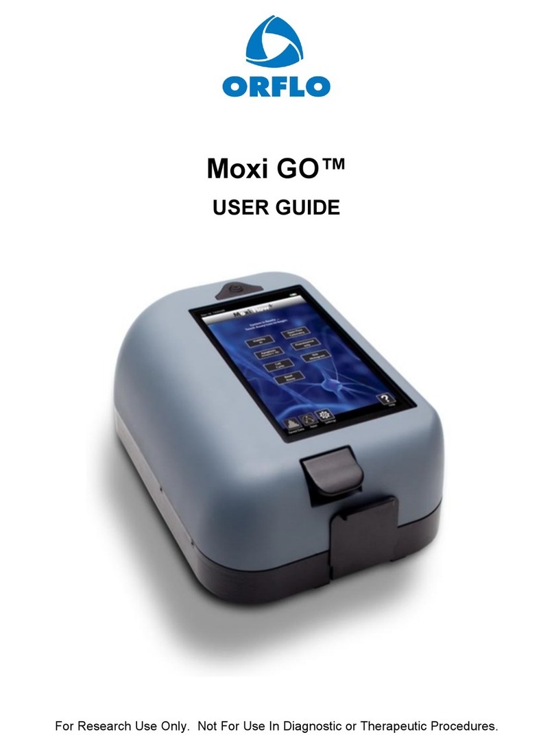
Orflo Moxi Flow User manual

For Research Use Only. Moxi Flow is not for use in diagnostic procedures.
MOXI FlowTM
USER GUIDE

The information in this document is subject to change without notice and should not be construed as a
commitment by ORFLO Technologies, a DBA of E.I. Spectra, LLC. Neither Orflo Technologies nor any of
its affiliated corporations assumes responsibility for any errors that may appear in this document. This
manual is believed to be complete and accurate at the time of publication. In no event shall Orflo
Technologies or any of its affiliated corporations be liable for incidental or consequential damages in
connection with or arising from the use of this manual.
© 2013 ORFLO Technologies, a DBA of E.I. Spectra, LLC. All rights reserved.
Rev. 1.4.3, 5/2016
The ORFLO symbol and Moxi Flow™are trademarks of E.I Spectra, LLC, registered in the U.S. and other countries.
Windows, Windows XP, Windows Vista, Windows 7, and Windows 8 are trademarks of Microsoft Corporation,
registered in the U.S. and other countries.
Mac and Mac OS are trademarks of Apple Corporation, registered in the U.S. and other countries.
FlowJo is a trademark of Treestar, Inc.
Bluetooth and the Bluetooth logos are registered trademarks of Bluetooth SIG, Inc., registered in the U.S. and other
countries.
Accutase is a registered trademark of Innovative Cell Technologies.
TÜV SÜD and the TÜV SÜD symbol are registered trademarks of TÜV SÜD Aktiengesellschaft.

Contents
Introduction ................................................................................................................................... 1!
About the User Guide ................................................................................................................... 1!
Conventions Used in the User Guide ........................................................................................... 1!
Safety Precautions........................................................................................................................ 2!
General Safety .......................................................................................................................... 2!
Laser Safety .............................................................................................................................. 2!
Biological Safety........................................................................................................................ 3!
Moxi FlowTM System Overview ..................................................................................................... 4!
Moxi FlowTM Accessories.............................................................................................................. 5!
Getting Started.............................................................................................................................. 6!
General Guidelines ....................................................................................................................... 6!
Materials Required........................................................................................................................ 7!
Using the Moxi FlowTM .................................................................................................................. 7!
Home (Start) Screen ................................................................................................................. 7!
Settings ..................................................................................................................................... 8!
Passcode Lock ...................................................................................................................... 8!
Fluorescence Gain ................................................................................................................ 9!
Analyzing a Sample .................................................................................................................. 9!
Sample Preparation Considerations...................................................................................... 9!
Running a Test ...................................................................................................................... 9!
Test Screen Output ................................................................................................................. 12!
Scatter/Dot Plot Output........................................................................................................ 12!
Histogram Output ................................................................................................................ 13!
Managing the Data.................................................................................................................. 14!
General Recommended Post-Test Workflow ...................................................................... 14!
Re-scaling the x axis (size range) ....................................................................................... 15!
Removing the noise region.................................................................................................. 15!
Gating the data .................................................................................................................... 16!

Test Naming and Renaming Tests ...................................................................................... 20!
Saving and Deleting Data/Tests.......................................................................................... 21!
Exporting Data Screenshots................................................................................................ 21!
Exporting Data – Connecting Via USB (USB on-the-go) ........................................................ 21!
Instrument Firmware and Software Upgrades ........................................................................ 24!
Updating Moxi FlowTM Firmware via USB ............................................................................... 24!
Moxi FlowTM Apps.................................................................................................................... 25!
Troubleshooting .......................................................................................................................... 26!
Maintenance and Storage........................................................................................................... 29!
Ordering Information................................................................................................................... 30!
Specifications for the Moxi FlowTM .............................................................................................. 31!
Technical Service ....................................................................................................................... 32!
Warranty ..................................................................................................................................... 33!
Applicable Patents ...................................................................................................................... 35!

Moxi Flow™User Guide
Page 1
Introduction
The ORFLO Moxi FlowTM is a portable, micro-flow cytometer that utilizes a disposable, thin-film
cassette and a combination of a 532nm laser, precision optics, 590/40nm filter set,
photomultiplier tube (PMT) analog and digital hardware, and proprietary software to perform
automated particle counting and analysis functions. It combines the gold standard Coulter
Principle with micro-flow cytometry to deliver highly accurate and repeatable results in less than
10 seconds per test.
The Moxi FlowTM performs very accurate cell counts and quantitative assessments of cell
viability, apoptosis, and other labeled antibody markers. The system is portable making it ideal
for use in a hood or multiple lab locations.Test results are displayed in the form of histograms
and scatter plots. The Moxi FlowTM can store up to 16Mb of data and, if desired, the data may
be downloaded to a PC or Mac via USB connectivity.
The system is intended for research use only and has been tested with cell types that are
representative of those commonly used.It is not intended for use in medical diagnostic
procedures.
About the User Guide
The Moxi FlowTM User Guide provides detailed information for operating, maintaining, and
troubleshooting the Moxi FlowTM system.
The user guide does not include instructions for analyzing the provided/output flow cytometry
standard (FCS) files offline.
Similarly, the user guide does not include information on preparing samples prior to running
them in the Moxi FlowTM. For more information on this topic, please visit www.orflo.com.
Conventions Used in the User Guide
WARNING Alerts you to a situation that may cause injury to the user.
CAUTION Alerts you to a situation that may cause damage to the system, loss of
data, or incorrect results.
NOTE Indicates additional related information that may be helpful to the user.

Moxi Flow™User Guide
Page 2
Safety Precautions
The Moxi FlowTM has integrated safety features that are designed for the protection of the user.
Use the Moxi FlowTM only as directed in this guide. Please review and understand the safety
instructions below before operating the system.
General Safety
WARNING To avoid the danger of electric shock:
•Prior to use, verify that the USB cable and USB charging adapter are plugged
securely into a properly grounded AC power outlet. Verify that the connection
between the USB cable and the instrument is secure and the AC power in your
location is within the specifications for the instrument (see page 31).
•Do not immerse the instrument, USB cable, or USB power adapter in liquid or allow
liquid to enter the instrument.
•Do not attempt to disassemble or service the Moxi FlowTM. The instrument has no
user serviceable parts. All service must be performed by ORFLO Technologies.
WARNING To avoid the danger of fire or explosion, do not use the Moxi FlowTM with
flammable or explosive liquids.
Laser Safety
WARNING The Moxi FlowTM is a Class 1 laser product in accordance with IEC 60825-
1:2014. The system contains a Class IIIb laser that operates at 532 nm with
a maximum output power of 50 mW. Direct exposure to laser radiation is
harmful. The following guidelines should be followed to avoid exposure:
•An interlock on the upper door prevents the laser from operating when the door is
open. Do not attempt to defeat the interlock and run a test with the door open.
•Do not operate the Moxi FlowTM if there is any damage to the instrument’s enclosure.
•The laser in the instrument is not adjustable or serviceable. Attempts to adjust or
service the laser may result in hazardous radiation exposure.

Moxi Flow™User Guide
Page 3
Biological Safety
WARNING Biological samples have the potential to transmit harmful or fatal disease.
The following guidelines should be followed to minimize the risk of exposure
to biohazardous materials.
•Handle all biological samples as if they are capable of transmitting harmful
infections.
•Wear appropriate personal protective equipment (PPE) including clothing, eyewear,
and gloves.
•Do not pipette by mouth.
•Dispose of biological waste in accordance with all applicable local, state, and
federal regulations.

Moxi Flow™User Guide
Page 4
Moxi FlowTM System Overview
The Moxi FlowTM Kit includes the Moxi FlowTM instrument, USB Cable, Power Adapter (US, UK,
and EU versions only), User Guide and one pack of 25 Cassettes.
USB Cable Port Touch Screen Display
Power/Reset Button Lower Door Upper Door
Disposable Test Cassette
Test 2 Fill Port
Test 1 Fill Port

Moxi Flow™User Guide
Page 5
Component Function
Touch Screen Display Allows user to interface with the instrument by pressing
on icons and targets. Displays all information needed for
operation and analysis of results.
Power/Reset Button Turns instrument on and off.
Resets the unit when pressed and held for >5 seconds.
Lower Door Manually opened and closed by user to allow insertion of
a test cassette.
Upper Door Manually opened and closed by user to allow loading of
a test sample. Door must be closed prior to running a test.
USB Cable Port Connects instrument to USB cable.
Cassette Disposable used for loading samples. Each cassette
contains two fill ports thereby allowing for two tests to be
run per cassette.
Moxi FlowTM Accessories
Power Adapter (US style) Power Adapter (EU style)
USB Cable Power Adapter (UK Style)

Moxi Flow™User Guide
Page 6
Part Function
USB Cable Connects instrument to PC/Mac or power adapter
Power Adapter, US Style Connects USB cable to a 110 VAC outlet
(US kit only)
Power Adaptor, UK Style Connects USB cable to a 230 VAC outlet
(UK kit only)
Power Adaptor, EU Style Connects USB cable to a 220 VAC outlet
(EU kit only)
Getting Started
The Moxi FlowTM is shipped in a condition ready for initial use. To begin, plug the USB Cable
into the instrument at one end (mini-USB). Plug the opposite end of the USB Cable (standard
USB) into the Power Adapter. Plug the Power Adapter into an AC outlet that matches the rating
of the Power Adapter.
CAUTION Use only an Orflo supplied USB Cable and Power Adapter. Use of other
products may result in inaccurate test results or damage to the
instrument.
NOTE Tests should only be performed with the instrument powered by an AC
source. Although the instrument has an internal, rechargeable battery,
Orflo strongly recommends that tests not be run on battery power alone.
General Guidelines
The Moxi FlowTM system is used with Moxi Type MF-M and Type MF-S Cassettes. Refer to the
Specifications section for information on the operating size and concentration ranges for the
system.
The sample volume for a test should be 75 µL.
Cells should be suspended in 0.9% salt solution (e.g. PBS or equivalent) to ensure proper
conductivity for unit operation and to ensure proper particle sizing. Water, hypotonic, or
hypertonic solutions are not acceptable diluents.
Cells need to be prepared as single-cell suspensions. Clusters/aggregates should be broken
apart with mechanical trituration and/or protease dissociation (e.g., Accutase - MXA020)
As the Moxi Flow™ uses a 532nm laser with a 590/40nm detection filter, dye/fluorophore

Moxi Flow™User Guide
Page 7
selection should be based accordingly (e.g. R-PE, PI, Suncoast Yellow). For assays other than
the “Open Flow Cytometry,” Orflo approved kits/reagents are strongly recommended.
Materials Required
•Cell or bead sample (diluted and dissociated, if necessary); 75 µL minimum.
•MF-S or MF-M cassette
•Pipette and appropriately sized pipette tips
•Cell staining/labeling reagents (test specific)
Using the Moxi FlowTM
Home (Start) Screen

Moxi Flow™User Guide
Page 8
Settings
Press the Power Button to turn on the instrument. Set the date and time by pressing the
Settings icon on the main menu of the Moxi FlowTM. Then use the arrow keys and follow the
instructions displayed on the screen.
!"##$%&'()%$*(
The Moxi Flow™ can be setup to require a password login to use the unit and access the units
data. To set the Password lock, use the left and right arrows on the Settings screen to highlight
the “Passcode Lock” field. Use the up or down arrows to change the “Passcode Lock” field
value to “On” and select Done. The system will present a keyboard to enter the four digit
numeric passcode. On entering the passcode, the user will be required to “Re-enter Passcode”
to prevent accidental entry of a wrong code. Upon successful re-entry of the passcode, the
system will display a “lock enabled” message. The system will now require a passcode for
access on initial startup and after entering sleep mode. Note: In order to turn the Passcode
Lock off, the user will be required to enter the correct passcode.
(

Moxi Flow™User Guide
Page 9
+,-%.'#$'/$'(0"1/(
The “Fluorescence Gain” field sets the level of fluorescence gain for the “Open Flow Cytometry”
only. Four possible values (Low, Default, Medium, High) can be entered here and will seed the
value of the dropdown list on the “Open Flow Cytometry” start screen. Note: the user can also
make a one-time (per-test) change to the fluorescent gain value of the “Open Flow Cytometry”
by touching the value on the test start screen as described in Step 3 of the “Analyzing a
Sample” | “Running a Test” section.
Analyzing a Sample
2"34,'(!.'4"."51%/(6%/#1&'."51%/#(
There are four key considerations for preparing a sample for analysis with the Moxi Flow:
1. Solution Conductivity – Cells must be suspended in 0.9% salt solution (e.g. PBS or
equivalent) for proper particle sizing and test function. Deviations of ~50% can be
tolerated without sacrificing count performance. However, the reported particle diameter
will vary accordingly (~ linear correlation b/w percent increase in measured volume and
percent in solution impedance)
2. Particle Size and Concentration - Tests must be run within the size and concentration
range specifications of the cassette being used. For Type MF-M cassettes, a dilution of
1:5 to 1:20 is recommended for most mammalian cell lines, but the appropriate dilution
will depend on cell type and seeding density. Type MF-S cassettes will typically require
NO to 1:5 dilution depending on cell type and seeding density. :
a. MF-S Cassettes:
i. Size Range: 3-16um effective diameter (14 – 2144fL volume)
ii. Concentration range: 1e4 – 1.75e6 total particles/ml
b. MF-M Cassettes:
i. Size Range: 4-22um effective diameter (34 – 5575fL volume)
ii. Concentration range: 1e4 – 7.5e5 total particles/ml
3. Single Cell Suspensions – While the Moxi Flow™ cassette does have a pre-filter for
removing the sporadic larger particles, cell samples should be prepared as single cell
suspensions to avoid clogging of cassettes. Clusters/aggregates can be broken apart
with mechanical trituration and/or protease dissociation (e.g. Accutase – MXA020).
4. Fluorescent Labeling/Stains - The Moxi Flow™ uses a 532nm laser for excitation with
a 590/40nm detection filter. Dye selection should be based accordingly (e.g. R-PE, PI,
Suncoast Yellow). For assays other than the “Open Flow Cytometry,” Orflo approved
kits/reagents, and associated preparation protocols, are strongly recommended
(www.ORFLO.com)
7-//1/8("(9'#5(
1. Please follow sample preparation guidelines above (“Sample Preparation
Considerations”) in preparing the sample. Note: The minimum volume required for a
test is 75 µL.

Moxi Flow™User Guide
Page 10
2. Turn the instrument on by pressing the
power button and the Home screen will be
displayed. Select a test type by pressing
one of the icons displayed on the screen.
NOTE: The instrument must be plugged in
to an AC source to run a test. Tests should
not be run on battery power alone.
3. Basic test instructions are presented for all tests (example for “Viability Test” shown to
the left below). For the “Open Flow Cytometry” test, the additional option of setting the
“Fluorescence Gain” is presented (image below/right). Touch the gray box (red arrow in
image) to change this gain. Four options, in order of increasing gain for the fluorescence
signal output, are possible: Low, Default, Medium, High. The initial value populated in
this field is determined by the global “Fluorescence Gain” setting that can be set from the
Settings icon off of the Home Screen.
4. Open the Upper and Lower Doors. Slide a test cassette into the tray and close both
Doors. The Moxi FlowTM will automatically perform a calibration step (all tests except
“Size Histogram”) as outlined below. The automated sequence aligns the laser to the
cassette flow cell (“System Calibration”), and prompts the user to open the OUTER door
Note: System status messages are displayed in the black bar at the top of the screen.

Moxi Flow™User Guide
Page 11
5. System messages at the top of the screen prompt the user to Open the Upper Door and
pipette a 75 µL sample into the fill port of the cassette (either test 1 or test 2, depending
on which end of the cassette was inserted into the instrument) and close the Upper
Door. The current disk usage space is also indicated at the bottom right of the screen at
this point. Note: The system provides the user a 60 second window to complete each
step (opening the outer door, loading the sample, waiting for the fluid to reach the start
electrode). If the time limit for any of the steps is exceeded, the test will automatically
cancel and the user will be returned to the Home screen
6. The Moxi FlowTM will begin the test. While the system waits for sample/fluid detection an
“Analyzing…” message is indicated in top left of the screen a countdown until the test is
auto-cancelled (auto cancel occurs after 60 seconds if no fluid is detected). Once the
fluid is detected, the system message changes to “Counting…” and the results are
dynamically populated on the scatter/dot plot. Results for most samples will be complete
in approximately 10 seconds but may be longer for higher concentration, sticky, or
aggregated samples.

Moxi Flow™User Guide
Page 12
Test Screen Output
The Moxi Flow™ test output screen components are fully labeled in the images below for both
the scatter/dot plot output and the size histogram output. More detailed workflow instructions for
each function are outlined in the “Managing the Data” section below.
2$"55'.:;%5(!,%5(<-54-5(
(
(

Moxi Flow™User Guide
Page 13
=1#5%8."3(<-54-5(

Moxi Flow™User Guide
Page 14
Managing the Data
Test results are presented to the user immediately following a test in the form of a scatter (dot)
plot (below/left) for fluorescent tests or as a size-only histogram (bottom/right, “Size Histogram”
test only).
Saved tests can be accessed by selecting the Saved Data icon off of the Home screen (Image
below left). Once selected, the user is presented with a list of saved test thumbnails (image
below right), ordered by test date/time. Note: the disk usage percentage is indicated in the
upper right corner of this screen. Selecting a thumbnail opens that test for editing, identical to
the post-test editing, with the exception that the size (x) axis rescale and noise gating
capabilities are no longer available.
0'/'.",(7'$%33'/&'&(!%#5>9'#5(?%.*@,%A(
Adjust the size
(x) axis to
optimize the
size
resolution.
Gate the test
results based
on fluorescent
intensity (red
markers).
Gate the test
results based
on size (blue
markers).
Read results and
perform file
operations (e.g.
export screenshot,
save, save gates)
Verify that the
noise auto-find
feature
properly
identifies the
noise. Adjust if
necessary.

Moxi Flow™User Guide
Page 15
7'>#$",1/8(5B'(C("C1#(D#1E'(."/8'F(
Upon completion of a test (but prior to saving the test), the x-axis scale can be adjusted. This is
accomplished by selecting the re-scale button below the scatter plot (magnifying glass with
arrow, see image sequence for an MF-S cassette below). With each button press, the text
under the button changes to indicate the scale range that will be displayed on the next button
push. The possible size scale ranges are:
•MF-S Cassettes: 2-25 µm, 2-17 µmand 2-9 µm.
•MF-M Cassettes: 3-33 µm, 3-25 µm, 3-17 µm, and 3-9 µm
Rescaling the axis results in reprocessing of the raw data to ensure that resolution is not lost
during the rescale process (1000 histogram bins). This allows (and is recommended for) users
to achieve finer resolution of smaller particle populations and potentially increased separation
between particle sub-populations. However, once a test has been saved, rescaling the x-
axis is not a possibility.
7'3%G1/8(5B'(/%1#'(.'81%/(
The Moxi Flow automatically identifies the noise region and removes it. To manually adjust the
noise gate, press the red gate button at the top right of the screen and toggle until the yellow
noise gate appears (see left image below). The yellow noise marker can then be dragged
around the noise region. Once the test has been saved, the noise region is permanently
removed and the noise gate cannot be re-adjusted.
Touch Rescale
Touch Rescale
Toggle
Noise Gate
Size Gates
Fl. Gate

Moxi Flow™User Guide
Page 16
0"51/8(5B'(&"5"(
Size%Gating%of%Scatter%(Dot)%Plots%
The results of all fluorescent tests (all tests except for the “Size Histogram” test) are initially
displayed as scatter plots with the size (blue) gates enabled (see image below, left). Gates can
be adjusted by dragging the blue markers around the edges of the scatter plot (left image
below). Touching the marker at the base of the left gate toggles the marker from green
(unlocked, left image below) to red (locked, middle image below). Touching the marker again
will switch it back to the prior state. Moving the left cursor with base unlocked (green) results in
the base moving synchronously/equivalently with the top left cursor (gate line is forced to be
vertical). Moving the left cursor with the base marker locked (red) anchors the base point
allowing the user to pivot the top point around it. This top cursor can even be dragged around
the left edge of the scatter plot if needed (right image below). Events to the left of the left size
gate and to the right of the right size gate are not included in the count totals or population
percentages (e.g. Live Cell %). The total particle count in the size-gated region is displayed
above the scatter plot, between the blue gating markers.
Fluorescent%Gating%of%Scatter%(Dot)%Plots% % %
To adjust the fluorescent (red) gate, the user can press the red gate toggle button at the top
right of the screen (see red arrow on the image to the left below). Touching this button enables
the red touch markers on the fluorescent gate line and disables the blue size gating markers
(see the image on the right below). Using that red gate toggle button, the user can switch back
and forth between size and fluorescent gating modes.
Information pertinent to the population above the fluorescent (red) gate and between the size
Left cursor can
wrap around the
side.
Drag blue cursors.
Touch dot at base
of left gate to pivot
left gate.
Toggle between
size and
Fluorescent Gates
Table of contents
Other Orflo Measuring Instrument manuals
Popular Measuring Instrument manuals by other brands

Wohler
Wohler A 550 Operation manual

ElektroPhysik
ElektroPhysik SmarTest quick start guide

PCB Piezotronics
PCB Piezotronics IMI SENSORS RTD602D11 Installation and operating manual

Kipp & Zonen
Kipp & Zonen LAS MkII ET System instruction manual

LaserLiner
LaserLiner SuperLine 2D operating instructions

Contrec
Contrec 415 user manual