manuals.online logo
Brands
  1. Home
  2. •
  3. Brands
  4. •
  5. Mastech
  6. •
  7. Measuring Instrument
  8. •
  9. Mastech MS2025C User manual

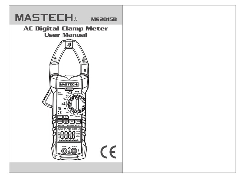
Mastech MS2025C User manual

MS2025C
CAT III
1000V
..................................01
......................................................01
.............................................................02
..........................................................03
...................................................03
......................................................05
....................................................07
...........................................................08
........................................09
.................................................13
...................................13
..................14
.............................................14
.............................................04
.........................................08
...............................13
............................................15
CONTENTS
1. Safety Information
1.1 Preliminary
1.2 Usage
1.3 Symbols
1.4 Maintenance
2. Description
2.1 Part Name
2.2 LCD Display
3. Specifications
3.1 General
3.2 Technical Indicators
4. Operating Guidance
4.1 Reading Hold
4.2 Relative Measurement
4.3 Manual Measuring Range Choice
4.4 Function Switch
4.5 Back light and
Clamp Head light
CONTENTS
4.6 Automatic Power-Off
4.7 Measurement Preparation
4.8 Current Measurement
4.9 AC Voltage Measurement
4.10 DC Voltage Measurement
4.12 Resistance Test
4.13 Diode Test
4.14 Circuit Continuity Test
4.15 Capacitance Measurement
4.16 Temperature Measurement
5. Maintenance
5.1 Replace Battery
5.2 Replace Probe
6. Accessories
4.17 NCV (non-contact voltage detection)
.....................................15
...................................16
.............................17
..........................18
...........................19
...........................................21
...................................................22
.................................22
.........................23
.........................23
..........23
.............................................24
..............................................25
..........................................24
...........................................25
.............................16
4.11 Frequency and Duty Cycle
1.2.13 Unless the meter bottom case and the battery cover are
completely fastened completely, do not use the meter.
Be extremely careful when using this meter. Improper use of
this device can result in electric shock or destruction of the
meter. Take all normal safety precautions and follow the
safeguards suggested in this manual. To exploit full
functionality of the meter and ensure safe operation, please
read carefully and follow the directions in this manual. If the
equipment is used in a manner not specified by the
manufacturer, the protection provided by the equipment may
be impaired.
WARNING
This meter is designed and manufactured according to safety
requirements of EN 61010-1, EN 61010-2-032,
EN 61010-2-033 concerning electronic measuring instruments
with a measurement CAT III 1000V and pollution degree 2 and
safety requirements for hand-held clamps for electrical
measurement and test.
1.1.3 If the meter is store and shipped under hard
conditions, please confirm if the meter is damaged.
1.1.4 Probe should be in good condition. Before use,
please check whether the probe insulation is
damaged and if the metal wire is bare.
1.1.5 Use the probes provided with the meter to ensure
safety. If necessary, replace the probe with another
identical probe or one with the same specification.
fter receiving the meter, please check for damage
that may have occurred during the transport.
1.3 Symbols
1.4 Maintenance
1.4.1 Don't try to open the meter bottom case to adjust or
repair. Such operations can only be performed by
technicians who fully understand the meter and
electrical shock hazard.
1.4.2 Before opening the meter bottom case or battery
cover, remove probe from the circuit to be measured.
1.4.3 To avoid wrong readings causing electric shock,
when " " appears on the meter display, replace
the battery immediately.
Note-Important safety information, refer to the
instruction manual.
Conforms to UL STD. 61010-1, 61010-2-032,
61010-2-033; Certified to CSA STD C22.2 NO.
61010-1, 61010-2-032,61010-2-033
Complies with European (EU) safety standards
Earth (ground) TERMINAL
Caution, possibility of electric shock
Equipment protected throughout by double
insulation or reinforced insulation.
Application around and removal from UNINSULATED
HAZARDOUS LIVE conductors is permitted.
Direct current
Alternating current
Both direct and alternating current
1.4.4 Clean the meter with damp cloth and mild detergent.
Do not use abrasives or solvents.
1.4.5 Power off the meter when the meter is not used.
Switch the measuring range to OFF position.
1.4.6 If the meter is not used for long time, remove the
battery to prevent the meter being damaged.
2. Description
- The meter is a portable, professional measuring
instrument with LCD display and back light for easy
reading by users. Measuring range switch is operated by
single hand for easy operation with overload protection
and low battery indicator. It is an ideal multifunction
meter for professionals, factories, schools, fans and
family use.
- The meter is used to measure AC current, AC voltage,
DC voltage, frequency, duty ratio, resistance,
capacitance measurement, temperature, NCV and circuit
connection, and to make diode tests.
- The meter has an auto measuring range function.
- The meter has a test data dual display function.
- The meter has a reading hold function.
- The meter has a relative test function.
- The meter has max. and min. display function.
- The meter has a manual measuring range selection
function.
- The meter has a back light function.
- The meter has a auto power-off function.
CAT III: MEASUREMENT CATEGORY III is applicable to
test and measuring circuits connected to the distribution
part of the building's low-voltage MAINS installation.
16
(16) Protective Barrier (to warn the operator of the limit of
safe access)
3.1.12 Power supply: DC 9V battery
(battery type: NEDA 1604, 006P or 6F22)
238x92x50mm
390
3 3
3 3
10
3.2.10 Duty cycle
0.1~99.9% 0.1% ±(3.0%)
4.11 Frequency And Duty Ratio Measurement
Electric shock hazard.
Remove the probe from the meter before
measuring with current clamp.
Warning
(1) Measuring switch is placed to position A .
(2) Hold the trigger, open clamp head, clip one lead of
measurement circuit to be tested in the clamp.
(3) Press Hz/% key to switch to frequency measuring
state.
(4) Rad the current value on the LCD display.
(5) Pressing Hz/% again can enter duty ratio measuring
state.
1) Clamp head measuring frequency
(through AC current):
Note:
(1) Clamping two or more leads of circuit to be tested
simultaneously will not get the correct
measuring results.
(2) Frequency measurement range is 10Hz~1kHz the
frequency to be tested is less than 10Hz, or if
frequency is higher than 10 kHz, accuracy is
not guarantee
(3) Duty ratio measuring range is 10 ~ 95%.
(4) “ ”means that maximum input current is 1000A AC
(RMS).
2) In Voltage Measurement Mode:
Electric shock hazard.
Pay special attention to avoid shock when
measuring high voltage.
Don't input voltage more than AC 750 RMS.
Warning
(1) Insert black probe to COM jack, insert red probe
to INPUT jack.
(2) Place transfer switch to or position, press
FUNC to enter AC voltage measurement state.
(3) Prss “Hz/%” key to switch to frequency measuring
state.
(4) onnect the probe with signal or both ends of load in
parallel for measurement.
(5) VRead on the LCD.
(6) Pressing “Hz/%”again can enter duty ratio measurig
state.
mV
V
(1) Frequency measurement range is 10Hz~1kHz
When the frequency to be tested is less than 10Hz,the
LCD will show “00.0” Masuring frequency higher than
10kHz is possible, but ccuracy is ot guarantee
(2) Duty ratio measuring range is 10 ~ 95%.
(3) “ ”means that maximum input voltage is 750V AC
(RMS).
Note:
3) In HZ/DUTY Measurement Mode:
Electric shock hazard.
Pay special attention to avoid shock when
measuring high voltage.
Don't input voltage more than AC 250V RMS.
Warning
5
(1) Insert black probe to COM jack, insert red probe to
NPUT ack.
(2) Transfer switch is placed to position HZ.
(3) Connect the probe with signal or both ends of load in
parallel for measurement.
(4) Read on the LCD.
(5) Pressing “Hz/%” again can enter duty ratio measuring
state.
Frequency measurement range is 10Hz~1kHz When the
frequency to be tested is more than 10Hz,the LCD will
show “00.0”measuring frequency higher than 10 kHz is
possible, but accuracy is not guarantee
Note:
5.1.1. If the symbol “ ” appears, it means that the batteries
should be replaced.
5.1.2. Loosen the screw of the battery cover and remove it.
5.1.3. Replace the used battery with a new one.
5.1.4. Return the battery cover and tighten the screw.
To avoid electric shock, make sure that the test leads have
been clearly move away from the circuit under
measurement before opening the battery cover.
The battery polarity can't be reversed.
Note:
WARNING
23 2 4
R-00-05-1805
5.2 Replace Probe
6. Accessories
Replace test leads if leads become damaged or worn.
Use meet EN 61010-031 standard, rated CAT III 1000V,
or better test leads.
WARNING
To avoid electric shock, make sure the probes are
disconnected from the measured circuit before
removing the rear cover. Make sure the rear cover is
tightly screwed before using the instrument.
WARNING
Test Probe 1 pair
1)
K-type temperature Probe 1 pcs
Operating Manual 1 pcs
9V DC battery (6FF2)
1 pcs
2)
3)
Case 1 pcs
4)
5)
25

Other Mastech Measuring Instrument manuals

Mastech MS2001 Assembly instructions

Mastech

Mastech MS2001 Assembly instructions

Mastech MS2010B User manual

Mastech

Mastech MS2010B User manual

Mastech MS8332C User manual

Mastech

Mastech MS8332C User manual

Mastech MS2140A User manual

Mastech

Mastech MS2140A User manual

Mastech MS6701 User manual

Mastech

Mastech MS6701 User manual

Mastech MS2025A User manual

Mastech

Mastech MS2025A User manual

Mastech MS2109A User manual

Mastech

Mastech MS2109A User manual

Mastech MS2208 User manual

Mastech

Mastech MS2208 User manual

Mastech MS2102 User manual

Mastech

Mastech MS2102 User manual

Mastech MS2205 User manual

Mastech

Mastech MS2205 User manual

Mastech MS5900 User manual

Mastech

Mastech MS5900 User manual

Mastech MS6460 User manual

Mastech

Mastech MS6460 User manual

Mastech MS6508 User manual

Mastech

Mastech MS6508 User manual

Mastech MS6503 User manual

Mastech

Mastech MS6503 User manual

Mastech MS2128 User manual

Mastech

Mastech MS2128 User manual

Mastech MS2026 User manual

Mastech

Mastech MS2026 User manual

Mastech MS2108 User manual

Mastech

Mastech MS2108 User manual

Mastech MS3300 Assembly instructions

Mastech

Mastech MS3300 Assembly instructions

Mastech MS2225A User manual

Mastech

Mastech MS2225A User manual

Mastech MS5908C User manual

Mastech

Mastech MS5908C User manual

Mastech MS2201 User manual

Mastech

Mastech MS2201 User manual

Mastech MS2015B User manual

Mastech

Mastech MS2015B User manual

Mastech MS20006 User manual

Mastech

Mastech MS20006 User manual

Mastech MS2010A User manual

Mastech

Mastech MS2010A User manual

Popular Measuring Instrument manuals by other brands

SMI SeeSV-S205 user manual

SMI

SMI SeeSV-S205 user manual

Anritsu MS2830A Configuration guide

Anritsu

Anritsu MS2830A Configuration guide

RLS Wacon SYCON P-value operating instructions

RLS Wacon

RLS Wacon SYCON P-value operating instructions

SEFRAM MW3036 user manual

SEFRAM

SEFRAM MW3036 user manual

Monroe Electronics Digital Stat-Arc 2 Operator's manual

Monroe Electronics

Monroe Electronics Digital Stat-Arc 2 Operator's manual

PCB Piezotronics 3991A1160KG Installation and operating manual

PCB Piezotronics

PCB Piezotronics 3991A1160KG Installation and operating manual

YOKOGAWA ROTAMASS Total Insight General instruction manual

YOKOGAWA

YOKOGAWA ROTAMASS Total Insight General instruction manual

LSI LASTEM Heat Shield Quick user guide

LSI LASTEM

LSI LASTEM Heat Shield Quick user guide

TechnipFMC Smith Meter AccuLoad IV Installation & maintenance manual

TechnipFMC

TechnipFMC Smith Meter AccuLoad IV Installation & maintenance manual

Datasensor DS3 Series instruction manual

Datasensor

Datasensor DS3 Series instruction manual

RNS electronics TripMaster GFX v2 Pro user manual

RNS electronics

RNS electronics TripMaster GFX v2 Pro user manual

Extech Instruments FM300 user manual

Extech Instruments

Extech Instruments FM300 user manual

RIEKER Flex MPI Series user guide

RIEKER

RIEKER Flex MPI Series user guide

Micromeritics GEMINI VII 2390 Service manual

Micromeritics

Micromeritics GEMINI VII 2390 Service manual

AEMC instruments SR759 user manual

AEMC instruments

AEMC instruments SR759 user manual

GC CORPORATION Fuji II LC CAPSULE user manual

GC CORPORATION

GC CORPORATION Fuji II LC CAPSULE user manual

IFM SM6x04 operating instructions

IFM

IFM SM6x04 operating instructions

KBR Multimess F96-***-5 Series quick guide

KBR

KBR Multimess F96-***-5 Series quick guide

manuals.online logo
manuals.online logoBrands
  • About & Mission
  • Contact us
  • Privacy Policy
  • Terms and Conditions

Copyright 2025 Manuals.Online. All Rights Reserved.