Oriel LIDA-SRS-KIT User manual

Family of Brands – ILX Lightwave® • New Focus™ • Ophir® • Corion • Richardson Gratings™ • Spectra-Physics®
MLIDA, Rev A
s
Lock-In Digital Amplifier
Radiometry System
User's Manual
LIDA-SRS-KIT

Family of Brands – ILX Lightwave® • New Focus™ • Ophir® • Corion • Richardson Gratings™ • Spectra-Physics®
MLIDA, Rev A
TABLE OF CONTENTS
1GENERAL INFORMATION..................................................................................................................4
1.1 SYMBOLS AND DEFINITIONS .............................................................................................4
1.2 GENERAL WARNINGS .........................................................................................................6
1.3 ELECTRICAL HAZARDS.......................................................................................................6
1.4 FIRE HAZARDS.....................................................................................................................6
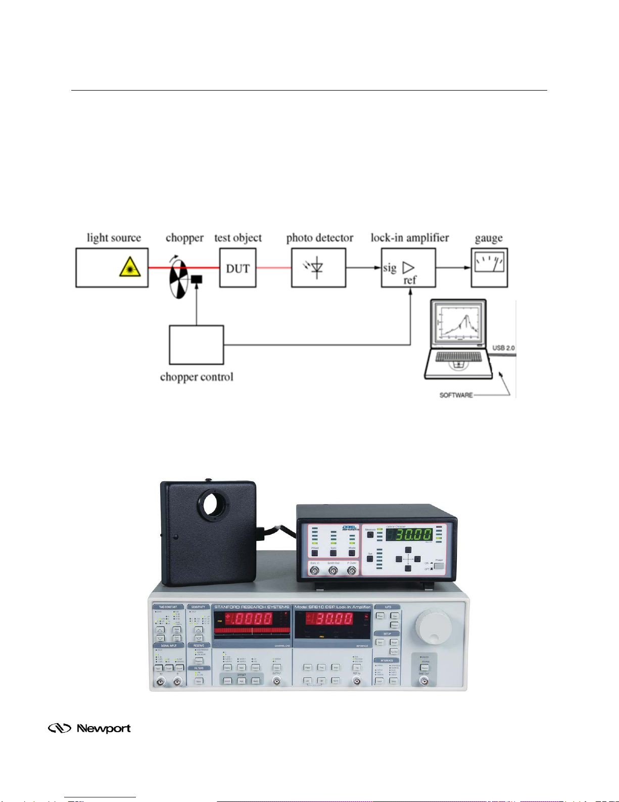
2INTRODUCTION..................................................................................................................................7
3FEATURES ..........................................................................................................................................8
3.1 SR810 LOCK-IN DIGITAL AMPLIFIER (LIDA)......................................................................8
3.1.1 Input Channel ............................................................................................9
3.1.2 Extended Dynamic Reserve ......................................................................9
3.1.3 Digital Filtering...........................................................................................9
3.1.4 Digital Phase Shifting.................................................................................9
3.1.5 Frequency Synthesizer..............................................................................9
3.1.6 Auto Functions.........................................................................................10
3.1.7 Analog Inputs and Outputs ......................................................................10
3.1.8 Internal Memory.......................................................................................10
3.1.9 Easy Operation........................................................................................10
4BASIC SYSTEM SETUP....................................................................................................................11
4.1 WHAT’S INCLUDED............................................................................................................11
4.2 REQUIRED ITEMS ..............................................................................................................11
4.3 UNPACKING........................................................................................................................11
4.4 CHOOSING A LOCATION...................................................................................................12
4.5 CHOPPER CONTROLLER CONNECTIONS......................................................................12
4.6 COMPUTER CONNECTIONS.............................................................................................13
4.7 DETECTOR CONNECTIONS..............................................................................................14
4.8 ELECTRICAL CONNECTIONS ...........................................................................................16
5SOFTWARE CONFIGURATION........................................................................................................17
5.1 ESTABLISHING COMMUNICATION...................................................................................17
5.2 SETTING OPERATING PARAMETERS..............................................................................19
6BASIC OPERATION...........................................................................................................................20
6.1 SET INTERNAL FREQUENCY GENERATOR....................................................................20
6.2 SET SIGNAL INPUT MODE ................................................................................................20
6.3 SET AUTO GAIN AND AUTO PHASE.................................................................................21
7ADVANCED CONFIGURATIONS AND APPLICATIONS..................................................................22
7.1 RATIO MODE SETUP..........................................................................................................22
7.2 CALIBRATION .....................................................................................................................24
7.3 QUANTUM EFFICIENCY MEASUREMENTS.....................................................................26
8DETECTORS .....................................................................................................................................28
8.1 ORIEL LIDA-COMPATIBLE DETECTORS..........................................................................28
8.2 OTHER DETECTORS..........................................................................................................29
9SPECIFICATIONS..............................................................................................................................30
10 WARRANTY AND SERVICE .............................................................................................................32
10.1 CONTACTING NEWPORT CORPORATION......................................................................32
10.2 REQUEST FOR ASSISTANCE / SERVICE.........................................................................33
10.3 REPAIR SERVICE...............................................................................................................33
10.4 NON-WARRANTY REPAIR.................................................................................................33
10.5 WARRANTY REPAIR ..........................................................................................................34
10.6 LOANER / DEMO MATERIAL..............................................................................................35

Family of Brands – ILX Lightwave® • New Focus™ • Ophir® • Corion • Richardson Gratings™ • Spectra-Physics®
MLIDA, Rev A
LIST OF FIGURES
Figure 1: Typical experimental setup...........................................................................................................7
Figure 2: The LIDA-SRS-KIT .......................................................................................................................7
Figure 3: Chopper Synchronization Connections ......................................................................................12
Figure 4: GPIB/USB Cable Connection.....................................................................................................13
Figure 5: Detector Signal Output Connection............................................................................................14
Figure 6: Detector Amplifier Cable Model CBL-70054-LIDA .....................................................................15
Figure 7: Amplifier Power Connection on SR810 with LIDA-Compatible Oriel Detector...........................15
Figure 8: Stand-Alone Preamplifier 70710 (left) with PMT Housing 70693...............................................15
Figure 9: Main Power Connector and On/Off Switch Locations ................................................................16
Figure 10: SR810 GPIB Address Selection ...............................................................................................17
Figure 11: View GPIB Address on SR810.................................................................................................18
Figure 12: LIDA Communication Established............................................................................................18
Figure 13: Setting Operating Parameters in TracQ Basic ..........................................................................19
Figure 14: Source Button, SINE out and Frequency Selector Knob...........................................................20
Figure 15: Signal Input Connections...........................................................................................................20
Figure 16: Auto Gain and Phase Buttons ...................................................................................................21
Figure 17: Reference Connections ............................................................................................................22
Figure 18: Reference Display.....................................................................................................................23
Figure 19: Ratio Measurement Configuration............................................................................................23
Figure 20: Oriel Monochromator Integration with TracQ Basic..................................................................24
Figure 21: Calibrated Detector File............................................................................................................25
Figure 22: Setting Detector Gain Value.....................................................................................................25
Figure 23: QE Measurement Configuration ...............................................................................................26
Figure 24: Reference Spectra Measurement Using TracQ Basic..............................................................27
Figure 25: QE Measurements of Samples.................................................................................................27
Figure 26: Oriel HgCdZnTe Detector.........................................................................................................29

Family of Brands – ILX Lightwave® • New Focus™ • Ophir® • Corion • Richardson Gratings™ • Spectra-Physics®
MLIDA, Rev A
1 GENERAL INFORMATION
Thank you for your purchase of this Lock-In Digital Amplifier System from Oriel Instruments.
Please carefully read the following important safety precautions prior to unpacking and operating this
equipment. In addition, please refer to the complete User’s Manual and all other documentation provided
for additional important notes and cautionary statements regarding the use and operation of the system.
Do not attempt to operate the system without reading all the information provided with each of the
components.
1.1 SYMBOLS AND DEFINITIONS
WARNING
Situation has the potential to cause bodily harm or death.
CAUTION
Situation has the potential to cause damage to property or equipment.
ELECTRICAL SHOCK
Hazard arising from dangerous voltage. Any mishandling could result
in irreparable damage to the equipment, and personal injury or death.
HOT SURFACE
Hazard arising from hot surfaces. Objects or persons making contact
with a hot surface could result in personal injury or damage to property
or equipment.
EUROPEAN UNION CE MARK
The presence of the CE Mark on Newport Corporation equipment
means that it has been designed, tested and certified as complying
with all applicable European Union (CE) regulations and
recommendations.
Note:
Additional important information the user or operator should consider.

Family of Brands – ILX Lightwave® • New Focus™ • Ophir® • Corion • Richardson Gratings™ • Spectra-Physics®
MLIDA, Rev A
WARNING
Situation has the potential to cause bodily harm or death.
ALTERNATING (AC) VOLTAGE
This international symbol designates an alternating voltage.
WEEE
This symbol on the product or on its packaging indicates that this
product must not be disposed of with regular waste. Instead, it is the
user’s responsibility to dispose of waste equipment according to the
local laws. The separate collection and recycling of the waste
equipment at the time of disposal will help to conserve natural
resources and ensure that the materials are recycled in a manner that
protects human health and the environment.
PROTECTIVE CONDUCTOR TERMINAL
The protective conductor terminal symbol in the above figure identifies
the location of the bonding terminal inside the unit, which is bonded to
conductive accessible parts of the enclosure for safety purposes.
ON
The ON symbol in the above figure indicates the ON position of the
power switch.
OFF
The OFF symbol in the above figure indicates the OFF position of the
power switch.
Please read all instructions that were provided prior to operation of the system. If
there are any questions, please contact Oriel Instruments or the representative
through whom the system was purchased.

Family of Brands – ILX Lightwave® • New Focus™ • Ophir® • Corion • Richardson Gratings™ • Spectra-Physics®
MLIDA, Rev A
1.2 GENERAL WARNINGS
•Read all warnings and operating instructions for this system prior to setup and use.
•Do not use this equipment in or near water.
•To prevent damage to the equipment, read the instructions in the equipment manual for proper
input voltage.
•This equipment is grounded through the grounding conductor of the power cords.
•Route power cords and other cables so they are not likely to be damaged.
•Disconnect power before cleaning the equipment
•Do not use liquid or aerosol cleaners; use only a damp lint-free cloth.
•Lock out all electrical power sources before servicing the equipment.
•To avoid explosion, do not operate this equipment in an explosive atmosphere.
•Qualified service personnel should perform safety checks after any service.
•If this equipment is used in a manner not specified in this manual, the protection provided by this
equipment may be impaired.
•To prevent damage to equipment when replacing fuses, locate and correct the problem that
caused the fuse to blow before re-applying power.
•Do not block ventilation openings.
•Do not position this product in such a manner that would make it difficult to disconnect the power
cords.
•Use only the specified replacement parts.
•Follow precautions for static sensitive devices when handling this equipment.
•This product should only be powered as described in the manual.
•Do not remove the cover for normal usage
1.3 ELECTRICAL HAZARDS
Make all connections to or from the power supply with the power off.
Do not use the lock-in digital amplifier without its cover in place. Lethal voltages are present inside.
1.4 FIRE HAZARDS
To avoid fire hazard, use only the specified fuses with the correct type number, voltage and
current ratings as referenced in the appropriate locations in the service instructions or on the
equipment. Only qualified service personnel should replace fuses.

Family of Brands – ILX Lightwave® • New Focus™ • Ophir® • Corion • Richardson Gratings™ • Spectra-Physics®
MLIDA, Rev A
2 INTRODUCTION
The LIDA-SRS-KIT is an easily integrated kit, which provides a powerful measurement metrology for
experiments by removing background signals through phase sensitive detection. This technique is often
used to extract very small signals obscured by noise sources many times larger by locking into the
specific modulation frequency of your desired signal.
Oriel created an application kit (LIDA-SRS-KIT) using the Stanford Research Systems (SRS) Lock In
Digital Amplifier (LIDA) model SR810. The LIDA-SRS-KIT includes the chopper, chopper control, and
lock-in amplifier and readout (gauge or software) used in a typical experimental set-up and connects to
any BNC-ended detector. A typical setup is shown in Figure 1.
Figure 1: Typical experimental setup
In Figure 2, the Oriel model 75160NF chopper controller sits on top of a Stanford Research Systems
(SRS) model SR810 Lock-In Digital Amplifier (LIDA) instrument. The chopper is being driven at 30Hz
through the internal frequency generator of the SR810.
Figure 2: The LIDA-SRS-KIT

Family of Brands – ILX Lightwave® • New Focus™ • Ophir® • Corion • Richardson Gratings™ • Spectra-Physics®
MLIDA, Rev A
3 FEATURES
The LIDA-SRS-KIT includes the chopper, chopper control, lock-in amplifier, and readout (gauge or
software) used in a typical experimental set-up and connects to any BNC-ended detector.
The Stanford Research Systems (SRS) SR810 Lock-In-Digital-Amplifier (LIDA) provides high
performance at a reasonable cost and integrates into Oriel’s product line.
•Single Channel
•Higher resolution frequency control
•Voltage or current input
•Wider range of time constant
•Internal or external reference frequency source
•Auto-gain, -phase, -reserve, and –offset
•Standard RS-232 and GPIB (IEEE488.2) interfaces
•“AUX IN” provides inputs for reference channels
•Reference input corrects your measurement channel to compensate for source drift
•“TTL OUT” controls the external chopper
•“PREAMP” connection may be used to power up detector pre-amplifiers
3.1 SR810 LOCK-IN DIGITAL AMPLIFIER (LIDA)
The SR810 Lock-in Digital Amplifier (LIDA) provides high performance at a reasonable cost.
Simultaneously displays the magnitude and uses digital signal processing (DSP) to replace the
demodulators, output filters, and amplifiers found in conventional lock-ins. The SR810 provides
uncompromised performance with an operating range of 1 MHz to 102 kHz and 100 dB of drift-free
dynamic reserve.
Lock-In Digital Amplifier model SR810
Oriel model 75160NF Optical Chopper System
Cable, BNC male to male (2 meters long)
Oriel TracQ Basic software
Cable, BNC male to male (2 meters long)
Cable, GPIB to USB
U.S. and European power cords
An electronic copy of this user’s manual on a thumb drive

Family of Brands – ILX Lightwave® • New Focus™ • Ophir® • Corion • Richardson Gratings™ • Spectra-Physics®
MLIDA, Rev A
3.1.1 Input Channel
The SR810 Lock-In Amplifiers have differential inputs with 6 nV/√Hz input noise. The input
impedance is 10 MΩ, and minimum full-scale input voltage sensitivity is 2 nV. The input can also
be configured for current measurements with selectable current gains of 106 and 108 V/A. A line
filter (50 Hz or 60 Hz) and a 2× line filter (100 Hz or 120 Hz) are provided to eliminate line related
interference. However, unlike conventional lock-in amplifiers, no tracking band-pass filter is
needed at the input. This filter is used by conventional lock-ins to increase dynamic reserve.
Unfortunately, band pass filters also introduce noise, amplitude and phase error, as well as drift.
The DSP based design of these lock-ins has such inherently large dynamic reserve that no
tracking band-pass filter is necessary.
3.1.2 Extended Dynamic Reserve
The dynamic reserve of a lock-in amplifier at a given full-scale input voltage is the ratio (in dB) of
the largest interfering signal to the full-scale input voltage. The largest interfering signal is
defined as the amplitude of the largest signal at any frequency that can be applied to the input
before the lock-in cannot measure a signal with its specified accuracy.
Conventional lock-in amplifiers use an analog demodulator to mix an input signal with a reference
signal. Dynamic reserve is limited to about 60 dB and these instruments suffer from poor
stability, output drift, and excessive gain and phase error. Demodulation in the SR810 Lock-In
Amplifier is accomplished by sampling the input signal with a high-precision A/D converter, and
multiplying the digitized input by a synthesized reference signal. This digital demodulation
technique results in more than 100 dB of true dynamic reserve (no prefiltering). It is free of the
errors associated with analog instruments.
3.1.3 Digital Filtering
The digital signal processor also handles the task of output filtering, allowing time constants from
10 µsec to 30,000 s, with a choice of 6, 12, 18 and 24 dB/oct roll-off. For low frequency
measurements (below 200 Hz), synchronous filters can be engaged to notch out multiples of the
reference frequency. Since the harmonics of the reference have been eliminated, (notably 2F),
effective output filtering can be achieved with much shorter time constants.
3.1.4 Digital Phase Shifting
Analog phase shifting circuits have also been replaced with a DSP calculation. Phase is
measured with 0.01° resolution, and the X and Y outputs are orthogonal to 0.001°.
3.1.5 Frequency Synthesizer
The built-in direct digital synthesis (DDS) source generates a very low distortion (-80 dBc)
reference signal. Single frequency sine waves can be generated from 1 MHz to 102 kHz with 4½
digits of resolution. Both frequency and amplitude can be set from the front panel or from a
computer. When using an external reference, the synthesized source is phase locked to the
reference signal.

Family of Brands – ILX Lightwave® • New Focus™ • Ophir® • Corion • Richardson Gratings™ • Spectra-Physics®
MLIDA, Rev A
3.1.6 Auto Functions
Auto-functions allow parameters that are frequently adjusted allowing automatic setting by the
instrument. Gain, phase, offset and dynamic reserve are each quickly optimized with a single key
press. The offset and expand features are useful when examining small fluctuations in a
measurement. The input signal is quickly nulled with the auto-offset function, and resolution is
increased by expanding around the relative value by up to 100×. Harmonic detection is no longer
limited to only the 2F component. Any harmonic (2F, 3F, ... nF) up to 102 kHz can now be
measured without changing the reference frequency.
3.1.7 Analog Inputs and Outputs
The SR810 has user-defined output for measuring X, R, X-noise, Aux1, Aux 2, or the ratio of the
input signal to an external voltage. The SR810 has X and Y analog outputs (rear panel) that are
updated at 256 kHz. Four auxiliary inputs (16-bit ADCs) are provided for general purpose use,
such as normalizing the input to source intensity fluctuations. Four programmable outputs (16-bit
DACs) provide voltages from -10.5 V to +10.5 V and can be set via the front panel or computer
interfaces.
3.1.8 Internal Memory
The SR810 Lock-In has an 8,000 point memory buffer for recording the time history of a
measurement at rates up to 512 samples/s. Data transfers from the buffers using the computer
interfaces. A trigger input provides externally synchronized data recording.
3.1.9 Easy Operation
The SR810 Lock-In Amplifier is simple to use. All instrument functions are set from the front-
panel keypad, and a spin knob is provided to quickly adjust parameters. Up to nine different
instrument configurations can be stored in non-volatile RAM for fast and easy instrument set-up.
Standard RS-232 and GPIB (IEEE-488.2) interfaces allow communication with computers. All
functions can be controlled and read through these interfaces.

Family of Brands – ILX Lightwave® • New Focus™ • Ophir® • Corion • Richardson Gratings™ • Spectra-Physics®
MLIDA, Rev A
4 BASIC SYSTEM SETUP
4.1 WHAT’S INCLUDED
The LIDA-SRS-KIT includes the following items:
Lock-In Digital Amplifier model SR810
Oriel model 75160NF Optical Chopper System
Cable, BNC male to male (2 meters long)
Oriel TracQ Basic software
Cable, BNC male to male (2 meters long)
Cable, GPIB to USB
U.S. and European power cords
An electronic copy of this user’s manual on a thumb drive
Please refer to the Optical Chopper System user’s manual for the items provided with the 75160NF.
4.2 REQUIRED ITEMS
The following items are required to be provided by the user for setting up the LIDA:
Computer for TracQ Basic software installation
Optical detector
Detector signal cable with BNC male connector
Refer to the TracQ Basic user’s manual for minimum system requirements for the computer. If an Oriel
LIDA-compatible detector is utilized, it includes a signal cable and amplifier power cable.
4.3 UNPACKING
Remove all items from the shipping containers and verify each item is accounted for.The system
is carefully packaged to minimize the possibility of damage during shipment. Inspect the shipping
boxes for external signs of damage or mishandling. Inspect the contents for damage.
If any item is missing or damaged, immediately contact Oriel Instruments or the Newport
representative from whom the system was purchased.
WARNING
Do not attempt
to operate this equipment if there is evidence of
shipping damage or there is suspicion that the equipment will not
operate correctly. Damaged equipment may present hazards.

Family of Brands – ILX Lightwave® • New Focus™ • Ophir® • Corion • Richardson Gratings™ • Spectra-Physics®
MLIDA, Rev A
4.4 CHOOSING A LOCATION
Choose an installation location where the power requirements can be met for the system. Be sure
power is not applied to the system until the setup has been completed.
The environment should be that of a typical laboratory atmosphere, without excessive humidity
and contaminants in the air. Do not allow the ventilation holes on the system’s components or its
computer to be blocked. Air should be able to circulate freely around the system.
4.5 CHOPPER CONTROLLER CONNECTIONS
A lock-in digital amplifier is capable of reading read chopped light signals from an optical detector.
Therefore, it is required to install the 75160NF Optical Chopper System. Install a wheel into the
chopper head based on the desired chopping frequency and beam size. When using a wheel with
more than two apertures, install the appropriate aperture disk supplied with the chopper head.
Use the cable supplied with the 75160NF to connect the chopper controller to the enclosed
chopper head. Refer to its user’s manual for more details.
Connect one end of the BNC cable supplied with the LIDA to “TTL OUT” on the back of the
SR810. Connect the other end to “REF” on the front of the chopper controller. This allows TracQ
Basic software to control the chopping frequency through the LIDA. For signal reading accuracy,
the frequency must be synchronized between the LIDA and the chopper.
Figure 3: Chopper Synchronization Connections

Family of Brands – ILX Lightwave® • New Focus™ • Ophir® • Corion • Richardson Gratings™ • Spectra-Physics®
MLIDA, Rev A
4.6 COMPUTER CONNECTIONS
Install the driver provided with the GPIB/USB cable from National Instruments. Connect the cable
to the GPIB connector on the back of the LIDA and tighten the connections. Plug the USB
connector into the computer. If successfully installed, the computer’s Device Manager will display
“GPIB USB HS”.
For computers which have a GPIB card, a standard GPIB cable may be used. This cable is
available from Newport as model 70038, and is ordered separately.
Figure 4: GPIB/USB Cable Connection

Family of Brands – ILX Lightwave® • New Focus™ • Ophir® • Corion • Richardson Gratings™ • Spectra-Physics®
MLIDA, Rev A
4.7 DETECTOR CONNECTIONS
The output signal from the detector is typically connected to the Channel “A” signal input BNC
connector on the front of the SR810. This connector may accept either current or voltage signals.
The B output from the preamp (preamp ground) may be connected to the B input of the SR810. In
this case, use A-B as the input configuration. Be sure to twist the A and B cables to avoid
differential noise pickup between the cables.
Unamplified detectors provide a current signal, while amplified detectors provide a voltage signal.
If the signal exceeds the maximum which can be read by the SR810, the “OVLD” indicator
illuminates. The SR810 has greater dynamic reserve when reading voltage signals, so the LIDA-
compatible detectors offered by Oriel are all amplified models. Additionally, Oriel offers the 70310
stand-alone current preamplifier to use with unamplified detectors or photomultiplier tubes.
Oriel’s amplified detectors and stand-alone current preamplifier require a power source to operate.
The “PREAMP” connection on the back of the SR810 is able to provide the power required. It
must be utilized with Oriel cable model CBL-70054-LIDA only. The user of any other Oriel cable
will damage the amplifier circuit and void the warranty on the detector or stand-alone preamplifier.
This power cable, as well as a BNC signal cable, are included with all LIDA-compatible detectors
offered by Oriel. For other setups, the CBL-70054-LIDA may be purchased separately. To use
this power cable with the model 70310 current preamplifier, the cable’s mini-DIN connector can be
cut off and the stripped wire ends may be installed into the preamplifier’s terminal block.
Note: the SR810 does NOT compensate for the gain of the preamp. The SR810 sets both
preamps to their maximum gains. Measurements made by the SR810 with a preamp should be
divided by the gain of the preamp.
Figure 5: Detector Signal Output Connection

Family of Brands – ILX Lightwave® • New Focus™ • Ophir® • Corion • Richardson Gratings™ • Spectra-Physics®
MLIDA, Rev A
Figure 6: Detector Amplifier Cable Model CBL-70054-LIDA
Figure 7: Amplifier Power Connection on SR810 with LIDA-Compatible Oriel Detector
Figure 8: Stand-Alone Preamplifier 70710 (left) with PMT Housing 70693

Family of Brands – ILX Lightwave® • New Focus™ • Ophir® • Corion • Richardson Gratings™ • Spectra-Physics®
MLIDA, Rev A
4.8 ELECTRICAL CONNECTIONS
Before powering up the system for the first time, it is suggested to have a qualified electrician
verify the wall socket to be used with the LIDA-SRS-KIT meets the requirements for operation as
noted.
Before making any electrical connections, verify the power switches are in the off position for the
lock-in digital amplifier and chopper controller.
WARNING
To avoid electric shock, connect the instrument to properly earth-
grounded, 3-
prong receptacles only. Failure to observe this
precaution can result in severe injury or death.
Refer to the specifications section of this users’ manual for the power requirements for the lock-in
digital amplifier. Refer to the specifications section of the 75160NF user’s manual for the power
requirements for the chopper controller.
The LIDA-SRS-KIT conforms to CE standards for both safety and EMC. During normal use, this
equipment will not pose any electrical hazards to the user. Read all warnings before installing or
operating this system. If there are any questions or concerns, contact Oriel Instruments or the
regional sales representative for Newport.
ELECTRICAL SHOCK
Never attempt to open the lock-in digital amplifier. This items does not
contain any user serviceable parts. Failure to follow this warning can
result in severe injury or death.
Figure 9: Main Power Connector and On/Off Switch Locations

Family of Brands – ILX Lightwave® • New Focus™ • Ophir® • Corion • Richardson Gratings™ • Spectra-Physics®
MLIDA, Rev A
5 SOFTWARE CONFIGURATION
Follow the instructions provided with TracQ Basic to install the software onto a computer. The software is
used to control the LIDA settings. After the setup is complete, TracQ Basic allows the user to select the
desired chopping frequency and operating parameters for the SR810.
The software is also able to control various Oriel monochromators. Please refer to the user’s manual
included with the software for a list of compatible instruments.
5.1 ESTABLISHING COMMUNICATION
The SR810 must be connected to the computer with the GPIB/USB cable and powered on before
opening the software application. When starting the TracQ Basic software for the first time,
prompts guide the user to select the detection instrument and monochromator for the system. If
no monochromator instrument is to be used, click Cancel. Otherwise, select the instrument based
on the instructions provided with the software.
To select the LIDA, navigate to the following folder:
C:\Program Files\Newport – Oriel Instruments\TracQ Basic.
Highlight the folder named “SR810”, then click Select Folder.
Verify that the indicator on the front panel of the software is green for the Detection Instrument and
monochromator, if utilized. If the SR810 communication cannot be established, go to Detector
Instr. Setup Communication and verify the appropriate GPIB address is selected.
The GPIB address should match the setting on the SR810. To view the GPIB address on the
SR810, press the Setup button under INTERFACE on the front panel of the instrument until the
Address LED is illuminated. The right side reference display will show the GPIB address. To
change the address, rotate the SR810 front panel knob.
Figure 10: SR810 GPIB Address Selection

Family of Brands – ILX Lightwave® • New Focus™ • Ophir® • Corion • Richardson Gratings™ • Spectra-Physics®
MLIDA, Rev A
Figure 11: View GPIB Address on SR810
Figure 12: LIDA Communication Established

Family of Brands – ILX Lightwave® • New Focus™ • Ophir® • Corion • Richardson Gratings™ • Spectra-Physics®
MLIDA, Rev A
5.2 SETTING OPERATING PARAMETERS
To set the chopping frequency and other operating parameters for the SR810, select Detection
Instr. Setup Parameters.
Figure 13: Setting Operating Parameters in TracQ Basic

Family of Brands – ILX Lightwave® • New Focus™ • Ophir® • Corion • Richardson Gratings™ • Spectra-Physics®
MLIDA, Rev A
6 BASIC OPERATION
6.1 SET INTERNAL FREQUENCY GENERATOR
Set the SR810 to lock using the internal frequency generator by pressing the SOURCE button on
the front panel of the instrument until the INTERNAL LED is active.
Figure 14: Source Button, SINE out and Frequency Selector Knob
6.2 SET SIGNAL INPUT MODE
Set the SR810 for current mode operation by pressing the INPUT button on the front panel of the
instrument until the I(106) or I(108) LED indicator is active. This is used with unamplified detectors.
Select A or A-B when using amplified detectors with a voltage signal.
Figure 15: Signal Input Connections
Table of contents