Oriental motor MB S Series User manual

1
㆙࿌
この警告事項に反した取り扱いをすると、死亡または重傷を負う場
合がある内容を示しています。
ὀព
この注意事項に反した取り扱いをすると、傷害を負うまたは物的損
害が発生する場合がある内容を示しています。
重要製品を正しくお使いいただくために、お客様に必ず守っていただき
たい事項を本文中の関連する取り扱い項目に記載しています。
[図記号の説明]
㆙࿌
•爆発性雰囲気、引火性ガスの雰囲気、腐食性の雰囲気、水のかかる場所、
可燃物のそばでは使用しないでください。火災・感電・けがの原因になります。
•通電状態で移動、設置、接続、点検の作業をしないでください。電源を切っ
てから作業してください。けがの原因になります。
•リード線を無理に曲げたり、引っ張ったり、はさみ込まないでください。
火災・感電の原因になります。
•ファンを分解・改造しないでください。けがの原因になります。
•設置、接続、運転・操作、点検・故障診断の作業は、適切な資格、知識を有
する人が行なってください。火災・感電・けがの原因になります。
•過熱保護装置(サーマルプロテクタ)がはたらいたときは、電源を切ってく
ださい。過熱保護装置が自動復帰したときにファンが突然起動して、けが・
装置破損の原因になります。
•ファンは、クラスⅠ機器です。設置するときは、保護接地端子を使って必
ず接地してください。感電の原因になります。
•ファンは筐体内に設置してください。感電・けがの原因になります。
•電源入力電圧は、定格範囲を必ず守ってください。火災・感電の原因にな
ります。
•接続は、接続図にもとづき確実に行なってください。火災・感電の原因に
なります。
•停電したときは、電源を切ってください。停電復旧時にファンが突然起動
して、けが・装置破損の原因になります。
ὀព
•ファンの仕様値を超えて使用しないでください。感電・けが・装置破損の原
因になります。
•ファンの開口部に指や物を入れないでください。けがの原因になります。
•運転中および停止後しばらくの間は、モーター部に触れないでください。
モーター部の表面が高温のため、やけどの原因になります。
•ファンの回転部(ランナー)やリード線で、製品を持ち上げないでください。
けがの原因になります。
•ファンの周囲に、可燃物を置かないでください。火災・やけどの原因にな
ります。
•ファンの周囲に、通風を妨げる障害物を置かないでください。装置破損の
原因になります。
•運転中は回転部(ランナー)に触れないでください。けがの原因になります。
フィンガーガードなどを使って保護してください。
•異常が発生したときは、ただちに運転を停止して、電源を切ってください。
火災・感電・けがの原因になります。
•ファンは筐体に確実に固定してください。けが・装置破損の原因になります。
•ファンは、正常な運転状態でもモーター部の表面温度が 70•°C
を超えることがあります。運転中のファンに接近する可能性
があるときは、図の警告ラベルをはっきり見える位置に貼っ
てください。やけどの原因になります。 警告ラベル
□•ファン•............................1台 □•コンデンサ•.....................1個
•••(単相入力のみ)
□•取扱説明書(本書)•..........1部 □•コンデンサキャップ•......1個
•••(単相入力のみ)
MB S 12 - JA
①②③④
① シリーズ名 MB
:
MBシリーズ
② タイプ S
:
Sタイプ
③ ランナー直径 12
:Ø120•mm
④
電源電圧 JA
:単相 100•V• UA
:単相 110/115•V
JC
:単相 200•V• EC
:単相 220/230•V
JS:三相 200•V• ES:三相 220/230•V
HF-3171-4
お買い上げいただきありがとうございます。
この取扱説明書には、製品の取り扱いかたや安全上の注意事項を示しています。
•取扱説明書をよくお読みになり、製品を安全にお使いください。
•お読みになったあとは、いつでも見られるところに必ず保管してください。
MBS

2
吸込口
吐出口
風方向
モーター部
ファンフレーム
回転部(ランナー)
周辺機器(別売)
□吐出口用取付金具
組付用ねじ:4本
ねじサイズ:M5
□取付台座
組付用ねじ:4本
コンデンサ組付用ねじ:1本
ねじサイズ:M4
[付属品] [付属品]
PASF12 PAS12
z
取付板
取付用ねじ
M5×4本
締付トルク:2.5N·m
4×M5
深さ:8mm
ばね座金
平座金
取付穴参考寸法図•
(単位:mm)
61
40
±0.2
4ר5.5
81
95±0.2
組付用ねじ(付属)
M5×4本
締付トルク:2.5N·m
吐出口用取付金具:
PASF12
取付板
取付用ねじ
M6×4本
締付トルク:3.0N·m
平座金
取付穴参考寸法図•
(単位:mm)
90
±0.2
110
95
±0.2
65
4×M6
z
取付用ねじ
M6×3本
締付トルク:3.0N·m
取付板
ナット
平座金
取付穴参考寸法図•
(単位:mm)
Ø135
3×
Ø6.5
20
80107
90 60
30
組付用ねじ(付属)
M4×4本
締付トルク:1.3N·m
取付台座:PAS12
重要必ず付属のねじで組み付けてください。首下が長いねじを使用すると製
品が破損するおそれがあります。
取付方向
取付板
地面
垂直方向
取付用ねじ
M5×4本
締付トルク:2.5N·m
平座金
重要垂直方向以外に取り付けないでください。製品や装置の振動により製品
が破損するおそれがあります。
吐出口用取付金具(別売)の取り付け 取付台座(別売)の取り付け

3
z
Ø4.3mm
組付用ねじ
M4×1本
締付トルク:1.0N·m
組付用ねじ(付属)
M4×1本
締付トルク:1.0N·m
モーター組付用ねじ
M6×4本
締付トルク:3.0N·m
重要モーター部は持ち上げて回転しないでください。モーター部を持ち上げ
て回転すると製品が破損するおそれがあります。
組付用ねじ(付属)
M5×4本
締付トルク:2.5N·
m
ダクト継ぎ手:FD12A
重要ダクト継ぎ手でファンを持ち上げないでください。製品が破損するおそ
れがあります。
組付用ねじ(付属)
M5×4本
締付トルク:2.5N·m
吐出口用フィンガーガード:FGB12E
S
FGB12ESPASF12 FD12A
FGB12 FLB12
接地
Ø4.1mm以上
4.8mm以下
9.5mm以下
重要必ず製品についている保護接地用のねじをご使用ください。首下が長い
ねじを使用すると装置が破損するおそれがあります。
z
接地
回転方向
L
N
電源
白
黒
赤
z
接地
回転方向
電源
白
黒
赤
L1(R)
L2(S
)
L3(T
)
コンデンサ
187シリー
ズ
コンデンサ
キャップ
187シリー
ズ
重要1 個の端子に 1 本のリード線を接続してください。
取付台座(別売)を使用の場合
ダクト継ぎ手(別売)の組み付け
吐出口用フィンガーガード(別売)の組み付け

4
重要ファンを運転するときはモーター部のケース温度を 90•°C以下に抑えて
ください。90•°Cを超えて運転すると、モーター巻線、ボールベアリン
グの寿命が短くなります。モーター部のケース温度は、温度計、サーモ
テープ、または熱電対で測定・確認してください。
ダンパ:DMP12
蝶ナット
8
6
4
2
8
6
4
2
8
6
4
小
大
風量
アジャスタ
重要蝶ナットは定期的に増し締めしてください。振動や衝撃で蝶ナットが
緩むおそれがあります。
組付用ねじ(付属)
M3×3本
締付トルク:0.4N·
m
重要必ず付属のねじで組み付けてください。首下が長いねじを使用すると製
品が破損するおそれがあります。
サーマルプロテクタ方式
z
適用規格 認証機関/ファイル No.
UL•507 UL / E58377
CSA•C22.2•No.113
z
適用規格
設置条件
(適用規格 EN規格)

1
Introduction
Before use
Only qualied personnel should work with the product. Use the product correctly after
thoroughly reading the section “Safety precautions.” In addition, be sure to observe the
contents described in warning, caution, and note in this manual. The product described in
this manual has been designed and manufactured to be incorporated in general industrial
equipment. Do not use for any other purpose. Oriental Motor Co., Ltd. is not responsible for
any damage caused through failure to observe this warning.
Safety precautions
The precautions described below are intended to ensure the safe and correct use of the
product, and to prevent the customer and others from exposure to the risk of injury. Use
the product only after carefully reading and fully understanding these instructions.
WARNING
Handling the product without observing the instructions
that accompany a "WARNING" symbol may result in serious
injury or death.
CAUTION
Handling the product without observing the instructions
that accompany a "CAUTION" symbol may result in injury or
property damage.
Note
The items under this heading contain important handling
instructions that the user should observe to ensure safe use
of the product.
Explanation of
graphic symbols
:Indicates "prohibited" actions that must not be performed.
: Indicates "compulsory" actions that must be performed.
WARNING
•Do not use the product in explosive or corrosive environments, in the
presence of ammable gases, locations subjected to splashing water, or near
combustibles. Doing so may result in re, electric shock or injury.
•Do not transport, install, connect, or inspect the product while the power is
supplied. Always turn o the power before carrying out these operations. Injury
may result.
•Do not forcibly bend, pull or pinch the lead wire. Doing so may result in re or
electric shock.
•Do not disassemble or modify the fan. Doing so may cause injury.
•Only qualied and educated personnel should be allowed to perform
installation, connection, operation and inspection/troubleshooting of the
product. Handling by unqualied and uneducated personnel may result in re,
electric shock or injury.
•Turn o the power in the event the overheat protection device (thermal
protector) is triggered. Failure to do so may result in injury or damage to
equipment, since the fan will start abruptly when the overheat protection
device (thermal protector) is automatically reset.
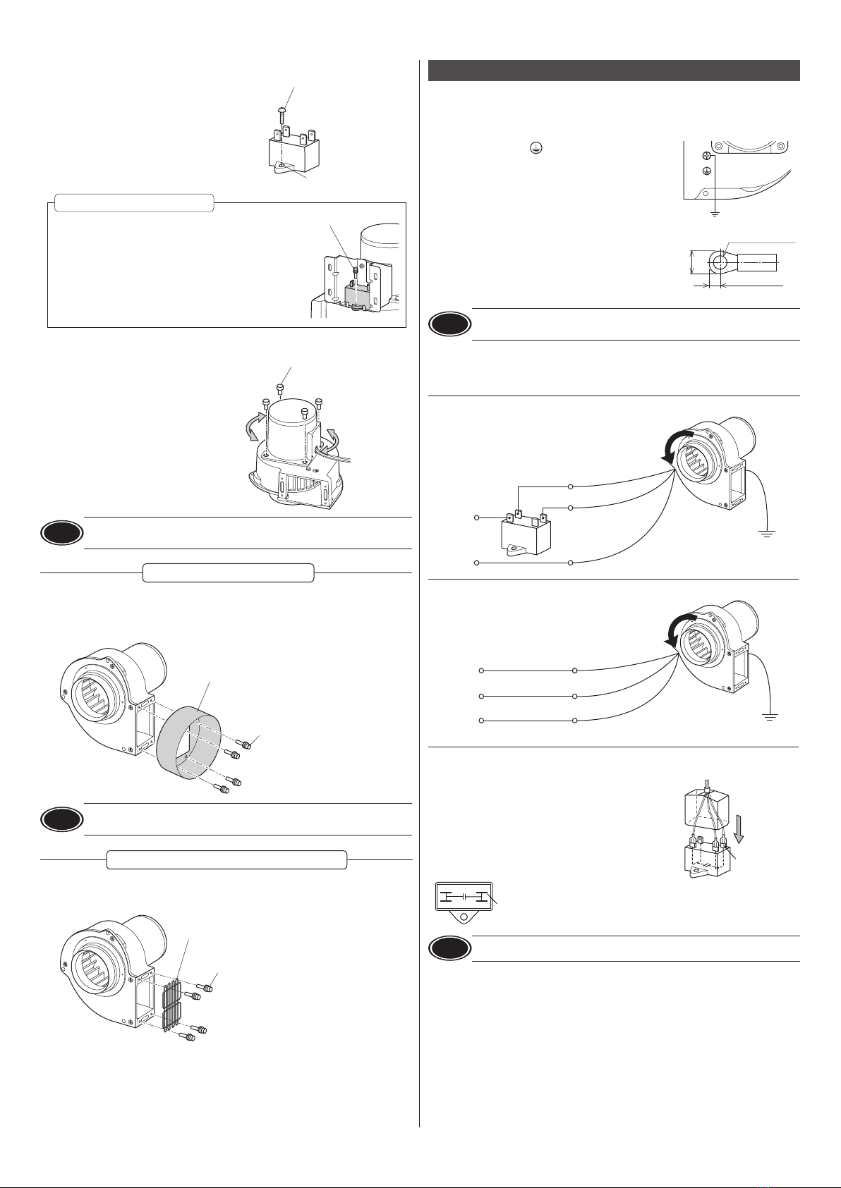
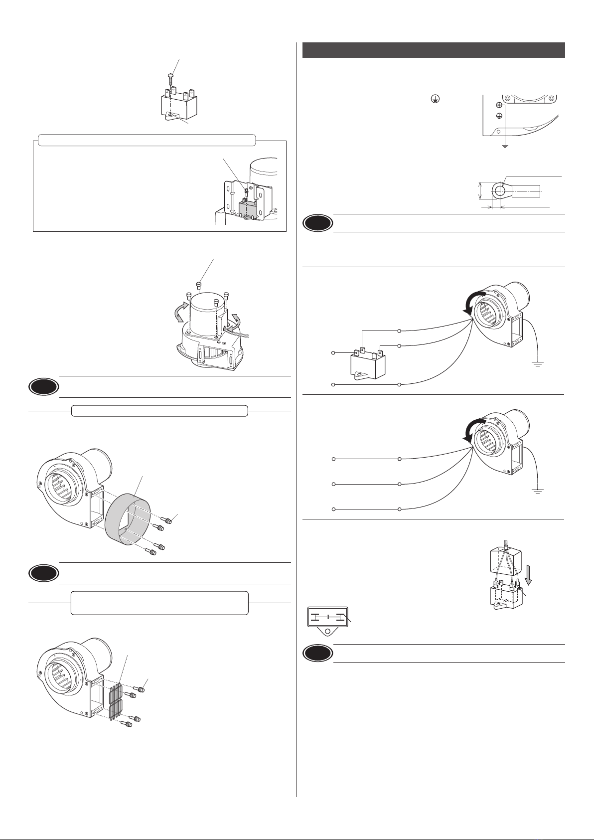
•The fan for ClassⅠequipment. Be sure to ground the Protective Earth Terminal
when installing the fan. Failure to do so may result in electric shock.
•Install the fan in an enclosure. Failure to do so may result in electric shock or
injury.
•Be sure to keep the input power voltage within the specied range. Failure to
do so may result in re or electric shock.
•Perform connections securely according to the connection diagram. Failure to
do so may result in re or electric shock.
•Turn o the power in the event of a power failure. Otherwise, the fan will start
unexpectedly when the power is restored. This may cause injury or damage to
equipment.
CAUTION
•Do not use the fan beyond its specications, or electric shock, injury or damage
to equipment may result.
•Keep your ngers and objects out of the openings in the fan. This may cause
injury.
•Do not touch the motor part while operating or immediately after stopping.
The surface is hot and it may cause a skin burn(s).
•Do not lift the product by holding the rotating part (impeller) or lead wire of
the fan. Doing so may cause injury.
•Keep the area around the fan free of combustible materials. Failure to do so
may result in re or a skin burn(s).
•Do not leave anything around the fan that would obstruct ventilation. Doing so
may result in damage to equipment.
•Do not touch the rotating part (impeller) when the fan is in operation. Doing
so may cause injury. The use of the nger guard is recommended to ensure
protection.
CAUTION
•Immediately when trouble has occurred, stop operation and turn o the power
supply. Failure to do so may result in re, electric shock or injury.
•Securely install the fan in an enclosure. Failure to do so may result in injury or
damage to equipment.
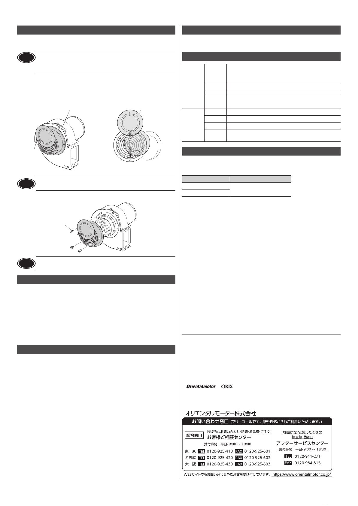
•The motor surface temperature of the fan may exceed 70 °C (158 °F)
even under normal operating conditions. If the operator is allowed to
approach the fan that is operating, attach a warning label as shown
in the gure in a conspicuous position. Failure to do so may result in
a skin burn(s).
Warning
label
Checking the product
Package contents
Verify that the items listed below are included. Report any missing or damaged items to
the branch or sales oce from which you purchased the product.
Fan .................................. 1 unit Capacitor ...................... 1 piece
(single-phase input only)
OPERATING MANUAL
(this document) ......... 1 copy
Capacitor cap .............. 1 piece
(single-phase input only)
Checking the model name
Verify the model name of the purchased product against the model shown on the name
plate of the product. Tell us the model name, product serial number, and manufacturing
date shown on the name plate when you contact us.
MB S 12 - JA
①②③④
①Series name MB: MB Series
②Type S: S type
③Impeller Diameter 12: Ø120 mm (Ø4.72 in.)
④Power supply
voltage
JA: Single-phase 100 VAC UA: Single-phase 110/115 VAC
JC: Single-phase 200 VAC EC: Single-phase 220/230 VAC
JS: Three-phase 200 VAC ES: Three-phase 220/230 VAC
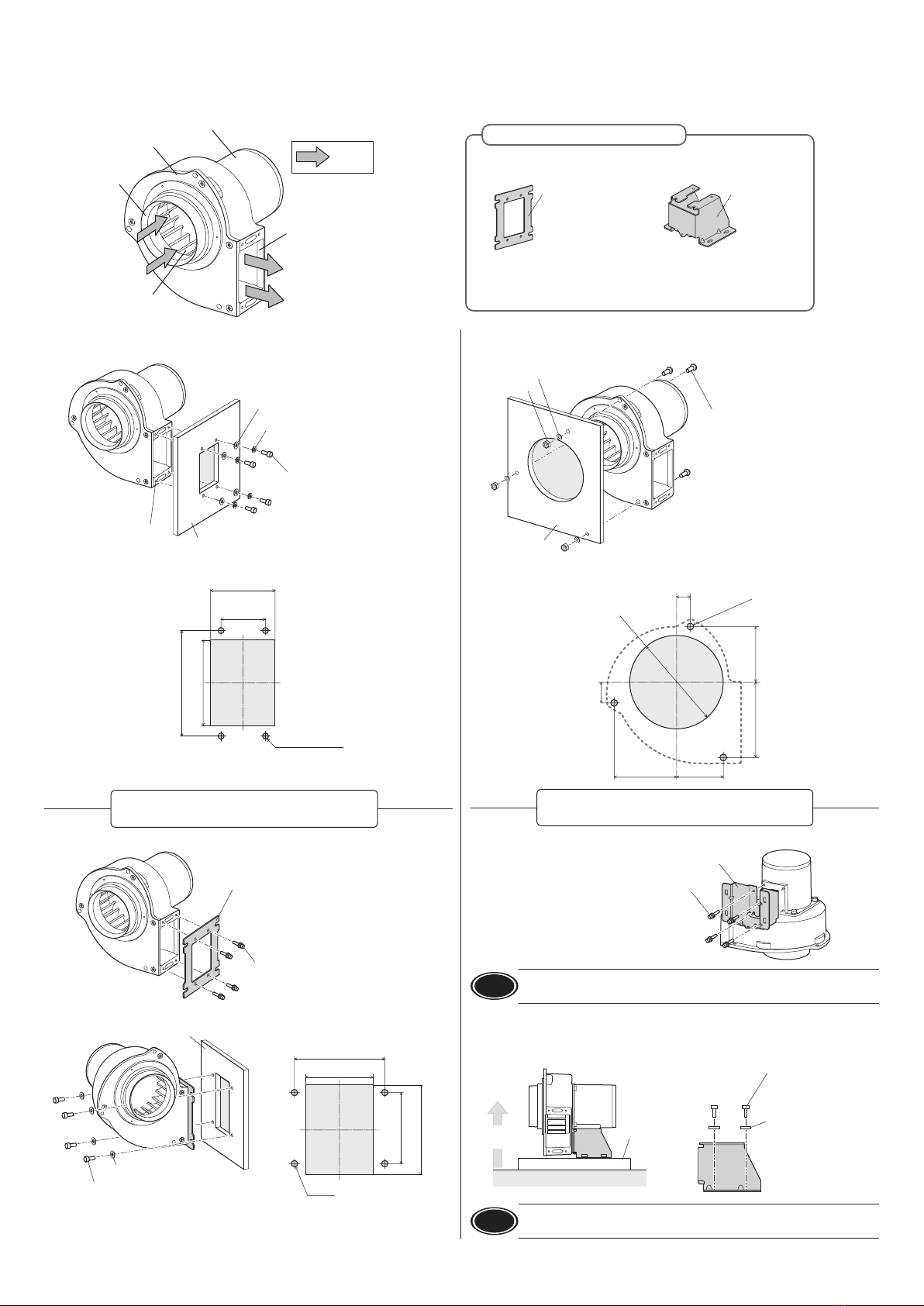
Installation
Location for installation
Install the product in a well-ventilated location that provides easy access for inspection.
The location must also satisfy the following conditions:
•Inside an enclosure that is installed indoors
•Operating ambient temperature:−10 to +50 °C [+14 to +122 °F] (non-freezing)*
* When the intake air temperature (temperature of air to be sucked) exceeds
+50 °C [+122 °F]: −10 to +40 °C [+14 to +104 °F].
(Range of intake air temperature: -10 to +90 °C [+14 to +194 °F])
•Operating ambient humidity: 85 % or less (non-condensing)
•Area that is free from an explosive atmosphere or toxic gas (such as sulfuric gas) or liquid
•Area not exposed to direct sun
•Area free of excessive amount dust, iron particles or the like
•Area not subject to splashing water (storms, water droplets), oil (oil droplets) or other
liquids
•Area not subject to continuous vibration or excessive shocks
•Area free of radioactive materials, magnetic elds or vacuum
•Altitude Up to 1000 m (3300 ft.) above sea level
•Area free of excessive electromagnetic noise (from welders, power machinery, etc.)When
using near a switching circuit or high-frequency power supply, the induced current may
ow inside the fan due to electromagnetic noise (conductive noise, radiative noise). If
the induced current ows, the electric corrosion is caused in the bearings of the fan. As a
result, it may generate the noise or shorten the service life of the products. Use the fan in
the environment that the electromagnetic noise does not cause.
HF-3171-4
OPERATING MANUAL Thank you for purchasing an Oriental Motor product.
This Operating Manual describes product handling procedures and safety precautions.
•Please read it thoroughly to ensure safe operation.
•Always keep the manual where it is readily available.
AC Centrifugal Blowers
MB Series S Type

2
zInstallation using the exhaust outlet of fan
Install the fan to equipment as shown in the gure.
Mounting plate
Mounting screw
M5-4 pieces
Tightening torque: 2.5 N·m (22 lb-in)
4×M5
Depth: 8 mm (0.315 in.)
Spring washer
Washer
Reference panel cut-out [Unit: mm (in.)]
61 (2.4)
40
±0.2
(1.575
±0.008
)
81 (3.19)
95±0.2 (3.74±0.008)
4ר5.5 (0.217)
Assemble the mounting bracket for exhaust outlet to the fan and install it to equipment.
Assembly screw (included)
M5-4 pieces
Tightening torque: 2.5 N·m (22 lb-in)
Mounting bracket for
exhaust outlet : PASF12
Mounting plate
Assembly screw
M6-4 pieces
Tightening torque: 3.0 N·m (26 lb-in)
Washer
Reference panel cut-out [Unit: mm (in.)]
90
±0.2
(3.543
±0.008
)
110(4.33)
95
±0.2
(3.74
±0.008
)
65
(2.56)
4×M6
zInstallation using the intake side of fan
Install the fan to equipment as shown in the gure.
Mounting screw
M6-3 pieces
Tightening torque: 3.0 N·m (26 lb-in)
Nut
Washer
Mounting plate
Reference panel cut-out [Unit: mm (in.)]
Ø135
(5.31)
3ר6.5
±0.1
(0.256
±0.004
)
20 (0.79)
80 (3.15)107 (4.21)
90 (3.54) 60 (2.36)
30 (1.18)
Assemble the installation pedestal to the fan and install it to equipment.
Assembly screw (included)
M4-4 pieces
T
ightening torque: 1.3 N·m (11.5 lb-in)
Installation pedestal: PAS12
Note Be sure to assemble using the included screws. Using a longer screw than the
included screws may cause damage to product.
• Installation direction
When installing the fan to equipment using the installation pedestal, install it in a direction
vertical to the ground as shown in the gure.
Mountin
g
plate
Ground
Vertical
direction
Mounting screw
M5-4 pieces
Tightening torque
:
2.5 N·m (22 lb-in)
Washer
Note Do not install in a direction other than a vertical direction. Doing so may
cause damage to the product due to vibration of the product or equipment.
Installation method
Install the fan onto an appropriate at metal plate having excellent vibration resistance and heat conductivity. Install the fan so that there is no gap between the mounting plate or
peripheral equipment and the fan. Screws other than the supplied screws should be provided by a customer.
Intake
Exhaust outlet
Air ow
Motor part
Fan frame
Rotating part
(impeller)
Peripheral equipment (sold separately)
□Mounting bracket for
exhaust outlet
Assembly screw: 4 pieces
Screw size: M5
□Installation pedestal
Assembly screw: 4 pieces
Capacitor mounting screw: 1 piece
Screw size: M4
[ Included ][Included ]
PASF12 PAS12
Installation using the mounting bracket
for exhaust outlet (sold separately)
Installation using the installation pedestal
(sold separately)

3
zMounting the capacitor (single-phase input only)
Mount the capacitor using the assembly
screw securely.
Ø4.3 mm (Ø0.169 in.)
Assembly screw
M4-1 piece
Tightening torque: 1.0 N·m (8.8 lb-in)
If the intake air temperature is
+50°C (+122°F) or below, the
capacitor can be mounted as
shown in the gure.
Assembly screw (included)
M4-1 piece
Tightening torque:
1.0 N·m (8.8 lb-in)
Changing the position of exhaust outlet
The position of the exhaust outlet can be
changed to the left or right 90-degree direction,
or the 180-degree direction. Loosen the motor
assembling screws with the intake side facing
downward as shown in the gure. Turn the motor
part without lifting it.
Motor assembling screws
M6-4 pieces
Tightening torque:
3.0 N·m (26 lb-in)
Note Do not lift the motor part to rotate it. Lifting the motor part may cause
damage to the product.
The duct joint (sold separately) is provided for attaching a duct.
Assemble as shown in the gure.
Applicable duct size (inner diameter): Ø125 mm (Ø4.92 in.)
Assembly screw (included)
M5-4 pieces
Tightening torque: 2.5 N·m (22 lb-in)
Duct joint: FD12A
Note Do not lift the fan with the duct joint. Doing so may cause damage to the
product.
Installing the nger guard for exhaust outlet (sold separately) can prevent ngers from
entering. Assemble as shown in the gure.
Assembly screw (included)
M5-4 pieces
Tightening torque: 2.5 N·m (22 lb-in)
Finger guard for exhaust outlet: FGB12ES
•When assembling FGB12ES together with PASF12 or FD12A to a fan
Provide screws (length: 12 mm [0.47 in.] ) with washer set (spring washer and plain
washer) separately.
The nger guard FGB12 and the lter FLB12 (both sold separately) are provided for intake
side. Use them in a condition where the intake air temperature is +50°C (+122°F) or below.
Connection
Insulate all connections such as connecting sections between the fan lead wires and the
power supply connections, and the capacitor connections.
Connecting Protective Earth Terminal
Ground using the Protective Earth Terminal of the fan.
Grounding
Applicable crimp terminal:
Insulated round crimp terminal
Terminal screw size: M4
Tightening torque: 1.0 to 1.3 N·m (8.8 to 11.5 lb-in)
Applicable lead wire: AWG18 (0.75 mm2) or thicker
Ø4.1 (0.16) or more
[ Unit: mm (in.) ]
4.8 (0.19) or less
9.5 (0.37)
or less
Note Be sure to use the screw for grounding attached on the product. Using a
longer screw than the included screw may damage to equipment.
Connection diagram
Check the fan model name used before connecting.
Use lead wires of AWG 20 (0.5 mm2) or thicker for a power supply.
zSingle-phase input
Grounding
Rotation
direction
L
N
Power
supply
White
Black
Red
zThree-phase input
Grounding
Rotation
direction
White
Black
Red
Power
supply
L1 (R)
L2 (S)
L3 (T)
Connecting the capacitor (single-phase input only)
When crimp terminals are used, use the FASTON terminals
187 Series (TE Connectivity).
Use the included capacitor cap to insulate the capacitor
terminal connection.
The capacitor has four terminals that are internally
connected as shown in the gure.
Capacitor
187 series
Capacitor
cap
<Capacitor internal wiring diagram>
187 series
Note For lead wire connection, use one lead wire for each individual terminal.
When using the installation pedestal (sold separately)
Assembling the duct joint (sold separately)
Assembling the nger guard for exhaust
outlet (sold separately)

•Unauthorized reproduction or copying of all or part of this manual is prohibited.
•Oriental Motor shall not be liable whatsoever for any problems relating to
industrial property rights arising from use of any information, circuit, equipment
or device provided or referenced in this manual.
•Characteristics, specications and dimensions are subject to change without
notice.
•While we make every eort to oer accurate information in the manual, we
welcome your input. Should you nd unclear descriptions, errors or omissions,
please contact the nearest oce.
•is a registered trademark or trademark of Oriental Motor Co., Ltd.,
in Japan and other countries.
© Copyright ORIENTAL MOTOR CO., LTD. 2019
Published in July 2020
T
echnical Support Tel:(800)468-3982
8:30
A.M. to 5:00 P.M., P.S.T. (M-F)
7:30
A.M. to 5:00 P.M., C.S.T. (M-F)
www
.orientalmotor.com
Schiessstraße 44, 40549 Düsseldor
f, Germany
T
echnical Support Tel:00 800/22 55 66 22
www
.orientalmotor.de
T
el:01256-347090
www
.oriental-motor.co.uk
T
el:01 47 86 97 50
www
.orientalmotor.fr
T
el:02-93906346
www
.orientalmotor.it
T
el:+55-11-3266-6018
www
.orientalmotor.com.br
• Please contact your nearest Oriental Motor oce for further information.
4-8-1Higashiueno
,Taito-ku,Tokyo 110-8536
Japan
T
el:03-6744-0361
www
.orientalmotor.co.jp
Tel:0800-060708
www.orientalmotor.com.tw
Singapore
Tel:1800-8420280
www.orientalmotor.com.sg
Tel:1800-806161
www.orientalmotor.com.my
Korea
Tel:080-777-2042
www.inaom.co.kr
Tel:1800-888-881
www.orientalmotor.co.th
Tel:400-820-6516
www.orientalmotor.com.cn
Tel:+91-80-41125586
www.orientalmotor.co.in
Hong Kong Branch
Tel:+852-2427-9800
4
Operation
The fan rotates when the power supply is turned on.
For protection against electric shock, do not turn on the power supply until the wiring is
complete.
Note Make sure that the motor case temperature does not exceed 90 °C (194 °F)
when operating the fan. Operation exceeding case temperature 90 °C (194°F)
may signicantly deteriorate the coils and ball bearings of the motor and
shorten the motor's life span. Motor case temperature can be measured by
xing a thermometer on the motor surface. It can also be measured using
thermo tape or a thermocouple.
Air ow adjustment
The air ow can be adjusted by assembling the damper for air ow adjustment (sold
separately) to the fan. Use numbers on the damper as a marker when adjusting the air ow
by moving the adjuster. The adjuster can be moved to either side of the right and left.
Damper :DMP12
Buttery nut
8
6
4
2
8
6
4
2
8
6
4
Small
Large
Air o
w
Adjuster
Note Retighten the buttery nut regularly. The buttery nut may loosen due to
vibrations or shocks.
Assemble as shown in the gure.
Assembly screw (included)
M3-3 pieces
T
ightening torque: 0.4 N·m (3.5 lb-in)
Note Be sure to assemble using the included screws. Using a longer screw than the
included screws may cause damage to product.
Locked rotor burnout protection
The fan is equipped with a function of burning protection for locked-rotor state.
• Thermal protection
The fan motor contains an automatic return type thermal protector in the motor windings.
When the motor internal temperature exceeds the specied value, the thermal protector is
activated to stop the fan. Always turn o the power before performing inspections.
Thermal protector activation range:
Power is turned o at 130±5 °C (266±9 °F)
Power is turned back on at 85±20 °C (185±36 °F)
Inspection and maintenance
Inspection
It is recommended that periodic inspections for the items listed below are conducted after
each operation.
If an abnormal condition is noted, discontinue any use and contact your nearest Oriental
Motor sales oce.
zInspection item
•Check if any of the screws of the fan and peripheral equipment is loose.
•Check if the fan generates unusual noises.
Warranty
Check on the Oriental Motor Website for the product warranty.
Disposal
Dispose the product correctly in accordance with laws and regulations, or instructions of
local governments.
Specications
Check on the Oriental Motor Website for the product specications.
General specications
Operating
environment
Ambient
temperature
−10 to +50°C [+14 to +122°F] (non-freezing)*
*When the intake air temperature (temperature of air to
be sucked) exceeds +50°C [+122°F]:
−10 to +40°C [+14 to +104°F]. (Range of intake air
temperature: -10 to +90°C [+14 to +194°F])
Ambient
humidity 85% or less (non-condensing)
Altitude Up to 1000 m (3300 ft.) above sea level
Surrounding
atmosphere
No corrosive gas, dust, water, or oil Cannot be used in
radioactive materials, magnetic eld, vacuum or other
special environment
Storage
environment
Shipping
environment
Ambient
temperature −10 to +60 °C [+14 to +140°F] (non-freezing)
Ambient
humidity 85% or less (non-condensing)
Altitude Up to 3000 m (10000 ft.) above sea level
Surrounding
atmosphere
No corrosive gas, dust, water, or oil Cannot be used in
radioactive materials, magnetic eld, vacuum or other
special environment
Regulations and standard
UL Standards and CSA Standards
This product is recognized by UL under the UL and CSA standards.
Applicable Standards Certication Body / File No.
UL 507 UL / E58377
CSA C22.2 No.113
•Thermal class UL/CSA Standards:130(B)
CE Marking
This fan is axed the CE Marking under the Low Voltage Directive.
zLow Voltage Directive
Applications standards
EN 62368-1
Installation conditions (For EN standard)
Overvoltage categoryⅡ, Pollution degree 2, ClassⅠequipment
If the specied values of the overvoltage category Ⅲis required based on the equipment,
supply the rated voltage to the fan via an isolation transformer.
RoHS Directive
The products do not contain the substances exceeding the restriction values of RoHS
Directive (2011/65/EU).
Table of contents
Other Oriental motor Blower manuals
Popular Blower manuals by other brands

Poulan Pro
Poulan Pro 530164107 instruction manual

Makita
Makita maktec MT401 technical information

Sonic Air Systems
Sonic Air Systems Sonic 150 Installation quick guide

Ryobi
Ryobi RY18BLXA Original instructions

Little Wonder
Little Wonder SHO LB601-00-01 Technical manual

Flymo
Flymo C-Li 20VB Operator's manual