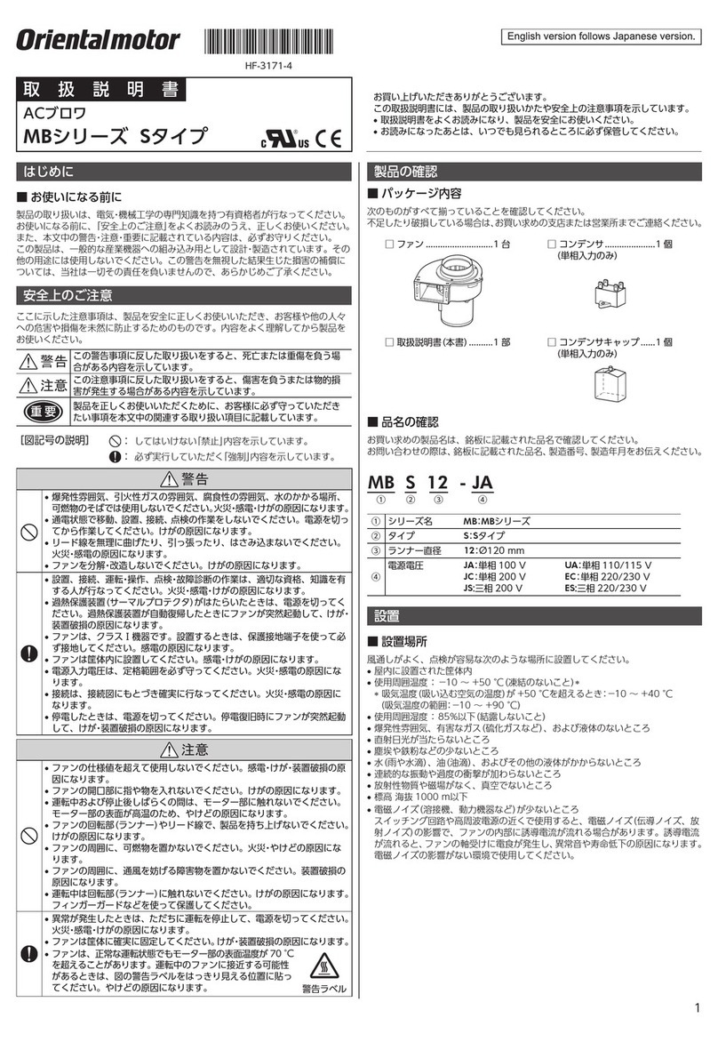
Oriental motor MBS Series User manual

1
HF-3123-4
OPERATING MANUAL Thank you for purchasing an Oriental Motor product.
This Operating Manual describes product handling procedures and
safety precautions.
•Please read it thoroughly to ensure safe operation.
•Always keep the manual where it is readily available.
AC Centrifugal Blowers MBS Series
Introduction
Before using the fan
Only qualied and educated personnel should work with the product.
Use the product correctly after thoroughly reading the section
“Safety precautions.” The product described in this manual has been
designed and manufactured to be incorporated in general industrial
equipment. Do not use for any other purpose. Oriental Motor Co.,
Ltd. is not responsible for any damage caused through failure to
observe this warning.
Standard and CE Marking
This product is recognized by UL and certied by CSA, and bears
the CE Marking (Low Voltage Directive) in compliance with the EN
Standards.
Standards
Applicable Standards Certication body
UL 507
CSA C22.2 No.113 UL
Installation conditions (For EN Standards)
Overvoltage category II, Pollution degree 2, Class I equipment
When connecting to a power supply of overvoltage category III,
supply power via the insulation transformer.
RoHS Directive
The products do not contain the substances exceeding the restriction
values of RoHS Directive (2011/65/EU).
Safety precautions
The precautions described below are intended to prevent danger or
injury to the user and other personnel through safe, correct use of
the product. Use the product only after carefully reading and fully
understanding these instructions.
Warning
Handling the product without observing the
instructions that accompany a “Warning” symbol may
result in serious injury or death.
Caution
Handling the product without observing the
instructions that accompany a “Caution” symbol may
result in injury or property damage.
Warning
•Do not use the product in explosive or corrosive environments, in
the presence of ammable gases, locations subjected to splashing
water, or near combustibles. Doing so may result in re, electric
shock or injury.
•Only qualied and educated personnel should be allowed to
perform installation, connection, operation and nspection/
troubleshooting of the product. Handling by unqualied and
uneducated personnel may result in re, electric shock or injury.
•Do not transport, install the product, perform connections or
inspections when the power is on. Always turn the power off before
carrying out these operations. Failure to do so may result in electric
shock.
•Turn off the power in the event the overheat protection device
(thermal protector) is triggered. Failure to do so may result in injury
or damage to equipment, since the fan will start abruptly when the
overheat protection device (thermal protector) is automatically
reset.
•The fan for class I equipment. Be sure to ground the protective
earth conductor when installing the fan. Failure to do so may result
in electric shock.
•Install the fan in an enclosure in order to prevent electric shock or
injury.
•Keep the input-power voltage within the specied range to avoid
re and electric shock.
•Connect the cables securely according to the wiring diagram in
order to prevent re and electric shock.
•Do not forcibly bend, pull or pinch the cable. Doing so may result
in re.
•Turn off the power in the event of a power failure, or the fan will
suddenly start when the power is restored and may cause injury or
damage to equipment.
•Do not disassemble or modify the fan. This may cause electric
shock or injury. Refer all such internal inspections and repairs to
the branch or sales ofce from which you purchased the product.
Caution
•Do not use the fan beyond its specications, or electric shock,
injury or damage to equipment may result.
•Keep your ngers and objects out of the openings in the fan. This
may cause injury.
•Do not touch the motor during operation or immediately after
stopping. The surface is hot and may cause a burn.
•Do not hold the lead wire. This may cause injury.
•Keep the area around the fan free of combustible materials in order
to prevent re or a burn.
•To prevent the risk of damage to equipment, leave nothing around
the fan that would obstruct ventilation.
•Do not touch the rotating parts (runner) when the fan is in
operation. This may cause injury.
•When an abnormality is noted, stop the operation immediately, or
re, electric shock or injury may occur.
•The motor’s surface temperature may exceed 70 °C
(158 °F), even under normal operating conditions. If
a fan is accessible during operation, post the warning
label shown in the gure in a conspicuous position to
prevent the risk of burns.
Warning
label
•Dispose the product correctly in accordance with laws and
regulations, or instructions of local governments.

2
Preparation
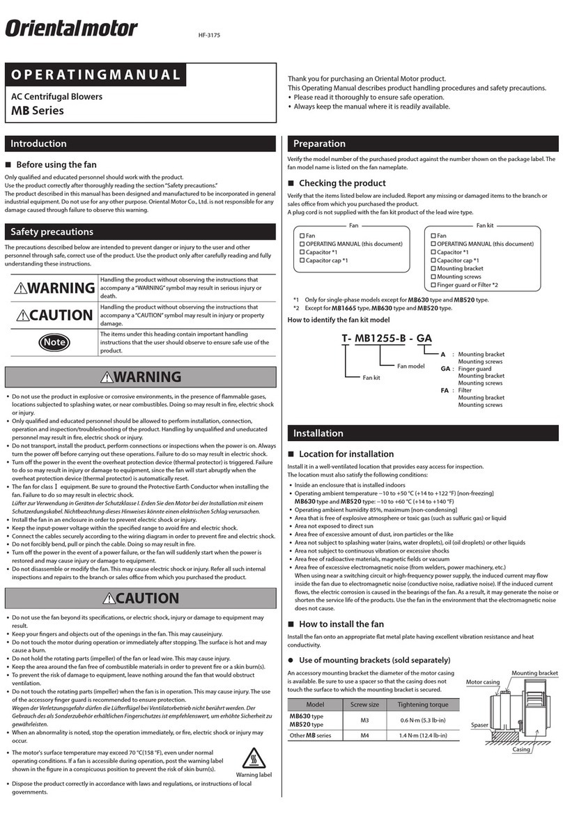
Checking the product
Upon opening the package, verify that the items listed below are
included. Report any missing or damaged items to the branch or
sales ofce from which you purchased the product.
•Fan .............................................................................. 1 pc.
•Power cable ................................................................ 1 pc.
•Air Control Louver ..................................................... 1 pc.
•Set of mounting screws for fan mounting .................. 1 set
(M5 Hexagonal socket head screws with captive washer,
Hexagonal nuts with ange 4 pcs. each)
•Mounting screws for Air Control Louver (M5 Cross-recessed pan
head screws with captive washer) .............................. 4 pcs.
•Operating manual (this manual) ................................. 1 copy
Checking the model name
To verify that the unit you’ve purchased is the correct one, check the
model number shown on the identication plate.
MBS18-BH, MBS18-BWH, MBS18-DH, MBS18-DWH,
MBS18-TH, MBS18-TWH, MBS20-BH, MBS20-BWH,
MBS20-DH, MBS20-DWH, MBS20-TH, MBS20-TWH
Installation
Location for installation
The fan is designed and manufactured for installation in equipment.
Install it in a well-ventilated location that provides easy access for
inspection. The location must also satisfy the following conditions:
•Inside an enclosure that is installed indoors
•Operating ambient temperature −10 to +60 °C (+14 to +140 °F)
(non-freezing)
•Operating ambient humidity 85% or less (non-condensing)
•Area that is free of explosive atmosphere or toxic gas (such as
sulfuric gas) or liquid
•Area not exposed to direct sun
•Area free of excessive amount of dust, iron particles or the like
•Area not subject to splashing water (rains, water droplets), oil (oil
droplets) or other liquids
•Area not subject to continuous vibration or excessive shocks
•Area free of radioactive materials, magnetic elds or vacuum
•Area free of excessive electromagnetic noise (from welders, power
machinery, etc.)
When using near a switching circuit or high-frequency power
supply, the induced current may ow inside the fan due to
electromagnetic noise (conductive noise, radiative noise). If the
induced current ows, the electric corrosion is caused in the
bearings of the fan. As a result, it may generate the noise or shorten
the service life of the products. Use the fan in the environment that
the electromagnetic noise does not cause.
How to install the fan
Install the fan onto an appropriate at metal plate having excellent
vibration resistance and heat conductivity. Consider the weight of the
fan and install the fan in a location where sufcient strength can be
ensured.
Drill mounting holes in your equipment and afx the fan using the
supplied screws and the four mounting holes provided in the fan
casing.
Tightening torque: 1.2 N·m
zInstalling method and installation dimensions
Motor side installation Installation dimensions
[Unit: mm (in.)]
L2
L1
L4
4ר5.5 (Ø0.217)
L1
Outflow
L5
L3
Model L1 L2 L3 L4 L5
MBS18-152.7
(6.012)
60
(2.36)
51
(2.01)
82
(3.23)
68
(2.68)
MBS20-166.9
(6.571)
59
(2.32)
52
(2.05)
92
(3.62)
68
(2.68)
Suction side installation Installation dimensions
[Unit: mm (in.)]
L2
L1
L4
L1
L3
Outflow
4ר5.5 (Ø0.217)
Model L1 L2 L3 L4
MBS18-152.7
(6.012)
4
(0.17)
13
(0.52)
107
(4.21)
MBS20-166.9
(6.571)
3.5
(0.14)
12.5
(0.49)
122
(4.8)
Exhaust side installation Installation dimensions
[Unit: mm (in.)]
L2
L1
L4
L3
4ר5.5 (Ø0.217)
Model L1 L2 L3 L4
MBS18-105
(4.13)
72
(2.83)
80
(3.15)
40
(1.57)
MBS20-120
(4.72)
72
(2.83)
92
(3.62)
40
(1.57)
Select mounting screws that are no more than 8 mm (0.315 in.)
longer than the thickness.

3
zInstallation method for Air Control Louver
Use the louver if airow must be controlled in a certain direction,
such as spot cooling.
The louver must be installed in the specied direction. Align the
projections on the louver with the holes in the blower outlet, and
afx the louver using the supplied screws.
Installation dimensions [Unit: mm (in.)]
25 (0.98) 10.5 (0.41)
3 (0.12)
4ר5.5
(Ø0.217)
40 (1.57)
L1
L2
L3
74 (2.90)
80 (3.15)
Applicable
model L1 L2 L3
MBS18-118 (4.65) 105 (4.13) 83 (3.27)
MBS20-134 (5.28) 120 (4.72) 95 (3.74)
zRotational direction and air orientation
Air flow
Rotation
Wiring
Single-phase
zMBS-BH, MBS-BWH, MBS-DH, MBS-DWH
Black
White
Green/Yellow
Grounding
Power cable
L
N
Three-phase
zMBS-TH, MBS-TWH
Red
White
Black
Green/Yellow
Power cable
L1 (R)
L2 (S)
L3 (T)
Grounding
zPower supply connector pin assignments
Single-phase Three-phase
Black (1)
White (2)
None (3)
Green/Yellow (4)
Red (1)
White (2)
Black (3)
Green/Yellow (4)
Projection Projection
zPower cable connector housings/contacts
Manufacturer: TE Connectivity
Housing model number: 350779-1
Contact model number: 350536-1
Poles: 4
Applicable minimum lead wire size: AWG18 (0.75 mm2)
Overheat protection
The fan uses a thermal protector for overheat protection. Once the
temperature reaches a specied level, the internal thermal protector
that has an automatic-return feature is triggered to stop the fan
operation.
Be sure to turn off the power when checking the thermal protector.
Operating temperature of thermal protectors
Open (Power OFF) .........130±5 °C (266±9 °F)
Close (Power ON) ..........82±15 °C (179.6±27 °F)

4
•Unauthorized reproduction or copying of all or part of this manual is
prohibited.
•Oriental Motor shall not be liable whatsoever for any problems
relating to industrial property rights arising from use of any
information, circuit, equipment or device provided or referenced in
this manual.
•Characteristics, specications and dimensions are subject to change
without notice.
•While we make every effort to offer accurate information in
the manual, we welcome your input. Should you nd unclear
descriptions, errors or omissions, please contact the nearest ofce.
• and are registered trademark or trademark
of Oriental Motor Co., Ltd., in Japan and other countries.
© Copyright ORIENTAL MOTOR CO., LTD. 2006
Published in November 2017
Technical Support Tel:(800)468-3982
8:30 A.M. to 5:00 P.M., P.S.T. (M-F)
7:30 A.M. to 5:00 P.M., C.S.T. (M-F)
www.orientalmotor.com
Schiessstraße 44, 40549 Düsseldorf, Germany
Technical Support Tel:00 800/22 55 66 22
www.orientalmotor.de
Tel:01256-347090
www.oriental-motor.co.uk
Tel:01 47 86 97 50
www.orientalmotor.fr
Tel:02-93906346
www.orientalmotor.it
Tel:+55-11-3266-6018
www.orientalmotor.com.br
• Please contact your nearest Oriental Motor oce for further information.
4-8-1Higashiueno,Taito-ku,Tokyo 110-8536
Japan
Tel:03-6744-0361
www.orientalmotor.co.jp
Tel:0800-060708
www.orientalmotor.com.tw
Singapore
Tel:1800-8420280
www.orientalmotor.com.sg
Tel:1800-806161
www.orientalmotor.com.my
Korea
Tel:080-777-2042
www.inaom.co.kr
Tel:1800-888-881
www.orientalmotor.co.th
Tel:400-820-6516
www.orientalmotor.com.cn
Tel:+91-80-41125586
www.orientalmotor.co.in
Hong Kong Branch
Tel:+852-2427-9800
Other Oriental motor Blower manuals
Popular Blower manuals by other brands

Lithium Earthwise
Lithium Earthwise LB20024 Operator's manual

EINHELL
EINHELL GE-CL 36 Li E Original operating instructions

EINHELL
EINHELL VENTURRO 18/210 operating instructions

Troy-Bilt
Troy-Bilt 657 Operator's manual

Weed Eater
Weed Eater VS2000BV instruction manual

KRAUSMANN
KRAUSMANN U37020-00 Operation manual