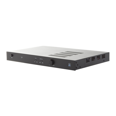
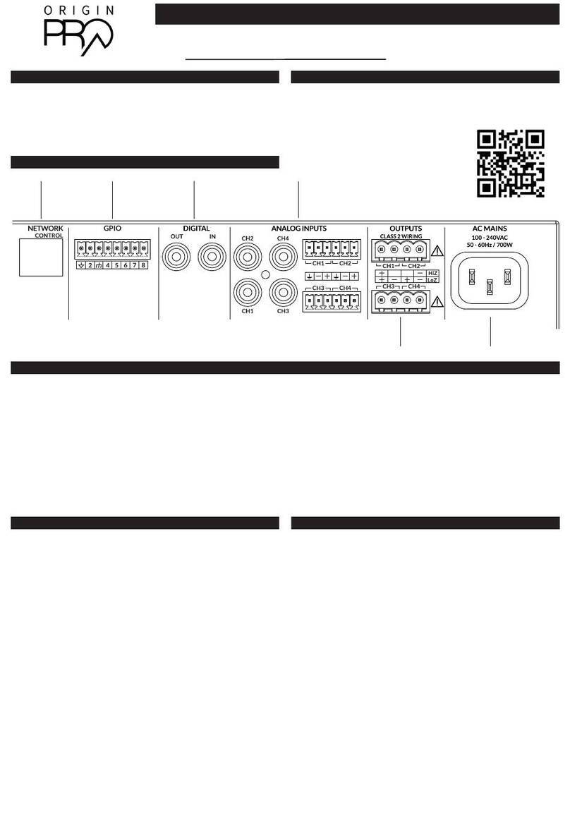
Origin Acoustics SUBA500 User manual

Installation Manual
SUBA-500
materials:K=K
565.0 325.0
125.0
SUBA500 SUBWOOFER AMPLIFIER
page | 3
FEATURES
IN
R
L
(LFE)
OUT
OUT
IN IR UPDATE
OPERATE
TRIGGER
DC 12V
EA-AMP-SUB-1D-500R
SUB 1 SUB 2
Total Impedance
(Sub 1 + Sub 2) Minimum 4Ω
100-120V AC
220-240V AC
FUSE T8AL/250V
100-120V~60Hz/220-240V~50Hz 500W ATTS
Designed and Engineered in US A
Made in China
A. POWER
Red: O/Standby
Blue: On/Operating
B. STATUS DISPLAY MENU
Displays current function/setting.
C. SELECTION KNOB/ROTARY ENCODER
Navigates and controls menu display functions.
D. RCA LINE LEVEL INPUTS
LFE IN: Connects the left female RCA input to an LFE output connection on a receiver or pre-amp processor.
L/R IN: Connects the left and right female RCA input to the left and right front output connections on a
receiver or pre-amp processor.
E. RCA LINE LEVEL OUTPUTS
OUT: Connects additional ampliers.
F. 12V TRIGGER IN/OUT
12V TRIGGER IN: Turns on the amp when a 12V signal is received from another 12V trigger device.
12V TRIGGER OUT: Sends a 12V signal to another 12V trigger device.
G. IR PORT
Connects IR device.
H. MINI USB PORT
Reserved for future use.
I. OPERATION MODE SWITCH
UPDATE: For future use only.
OPERATE: Normal function.
J. SPEAKER OUTPUTS
Connects the speaker wires to the binding posts.
NOTE: Total impedance (SUB 1 + SUB 2) should not be less than 4Ω.
K. VOLTAGE SELECTOR
Selects the appropriate input voltage setting: 100V or 220V.
L. AC POWER IN
IEC power cord.
M. FUSE
Additional fuse included for servicing.
N. MASTER POWER SWITCH
Switch between on/o.
D E F G H I J K L M N
SUBA500 SUBWOOFER AMPLIFIER

IMPORTANT SAFETY INSTRUCTIONS
• Read these instructions
• Keep these instructions
• Heed all warnings
• Follow all instructions
• Do not use apparatus near water
• Clean only with dry cloth
• Do not block any ventilation openings. Install in accordance with the
manufacturer’s instructions
• Do not install near any heart sources such as radiators, head registers,
stoves, or other apparatus including amplifiers that produce heart
• Do not install near heat sources such as radiators heat registers, stoves,
or other apparatus (including amplifiers) that produce heat.
• Do not defeat the safety purpose of polarized or grounding type plug. A
polarized plug has two blades with one wider than the other. A grounding type
plug has two blades and a third grounding plug. The wide blade or the third prong
are provided for you safety. If the plug does not fit into your outlet consult an
electrician for replacement or the obsolete outlet.
• Protect the power plug from being walked on or pinched particularly at
plugs, convenience receptacles, and the point where they exit from the apparatus.
• Only user attachments/accessories specified by the manufacturer.
• Use only with the cart, stand, tripod, or table specified by the
manufacturer or sold with the apparatus. When a cart is used, use caution when
moving the car/apparatus combination to avoid injury form tipping over.

• Unplug this apparatus during lightning storms or when unused for
period of times.
• Refer all servicing to qualified service personnel. Servicing is required
when the apparatus had been damaged, liquid had been damaged in any way,
such as power supply cord or plug id damaged, liquid had been dropped or
objects have fallen into the apparatus, the apparatus has been exposed to rain or
moisture, does not operate normally or has been dropped.
• The equipment shall be used at a maximum temperature of 35 degrees
Celsius ambient temperature.
• Do not open the equipment to reduce the risk of electric shock. For
safety reasons it is only allowed to be opened by a qualified service person.
• WARNING: To reduce the risk of fire or electric shock, do not expose this
apparatus to the rain or moisture. And the apparatus shall not be e3xposed to
dripping or splashing and that no objects filled with liquid, such as vases, shall be
placed on the apparatus.
• The MAINS plug is used as a disconnect device and shall remain
readily operable.
• The product shall be used in an open area or bench.
• No naked flame sources, such as lighted candles, should be placed on
the apparatus.
• The apparatus should be connected to a mains socket outlet with a
protective earthing connection.
• Ventilation should not be impeded by covering the ventilation openings
with items, such as newspapers, table-cloths, curtains, etc.
• This apparatus is suitable for use in tropical climates.

Introduction 1
Amplifier Specifications 2
Amplifier Features | Menu Display | Functions 3
Setup Guide 4
Fine Tuning 4
Trouble Shooting 6
Technical Assistance 6
Warranty 8
Return Process 9

SUBA -500 AMPLIFIER INSTALLATION USER MANUAL
1
Thank you for purchasing the SubA Series amplifier. At Origin Acoustics, we take pride in
providing you with a high quality product. All of Origin Acoustics’ products are designed to
have excellent sound quality, longevity, and a simple installation process.
This instruction booklet covers the necessary information for a smooth installation,
including: the tools you will need, step-by-step instructions for installation, troubleshooting
tips for any errors that may occur, and all warranty information. If for any reason you
experience problems or if you have installation questions please call us at (844) 674-4461.
Hours of operation are 8:00am to 5:00pm (Pacific Time), Monday through Friday.
Introduction

2
SUBA -500 AMPLIFIER INSTALLATION USER MANUAL
250 watts RMS at 8 ohms
500 watts RMS at 4 ohms (< 0.5% THD)
100 mV for 500W output 4 ohms
15,000 ohms
88 dB (5 kHz bandwidth relative to 500W @ 4 ohms)
-1.1dB at 300 Hz (Flat EQ, LFE Crossover Setting)
-1.5dB at 20 Hz
< 0.2%
< 5.5 mV (Le)
< 22 mV (Right)
12V +/-1.2V no load
10.5 V with 100 mA load)
2.6 V
3.5 ohms (4 ohm minimum speaker load)
3.6 V RMS (L + R, 20 Volume, 40 Hz Signal, Flat EQ, LFE Crossover)
16.9” W (19” including rack mounts)
1.75” H (2.1” including feet)
8.1” D (front switch to rear chassis)
8.9” D (front switch rear speaker connector)
8.5 lb
TUV Listed and tested under UL/EN60065 for US and Canada

SUBA -500 AMPLIFIER INSTALLATION USER MANUAL
3
*Rack Ears For Dual 1U Mount Sold Separately
SUBA500 SUBWOOFER AMPLIFIER
page | 3
FEATURES
IN
R
L
(LFE)
OUT
OUT
IN IR UPDATE
OPERATE
TRIGGER
DC 12V
EA-AMP-SUB-1D-500R
SUB 1 SUB 2
TotalImpedance
(Sub 1 + Sub 2) Minimum 4Ω
100-120V AC
220-240V AC
FUSE T8AL/250V
100-120V~60Hz/220-240V~50Hz 500W ATTS
Designed and Engineered in US A
Made in China
A. POWER
Red: O/Standby
Blue: On/Operating
B. STATUS DISPLAY MENU
Displays current function/setting.
C. SELECTION KNOB/ROTARY ENCODER
Navigates and controls menu display functions.
D. RCA LINE LEVEL INPUTS
LFE IN: Connects the left female RCA input to an LFE output connection on a receiver or pre-amp processor.
L/R IN: Connects the left and right female RCA input to the left and right front output connections on a
receiver or pre-amp processor.
E. RCA LINE LEVEL OUTPUTS
OUT: Connects additional ampliers.
F. 12V TRIGGER IN/OUT
12V TRIGGER IN: Turns on the amp when a 12V signal is received from another 12V trigger device.
12V TRIGGER OUT: Sends a 12V signal to another 12V trigger device.
G. IR PORT
Connects IR device.
H. MINI USB PORT
Reserved for future use.
I. OPERATION MODE SWITCH
UPDATE: For future use only.
OPERATE: Normal function.
J. SPEAKER OUTPUTS
Connects the speaker wires to the binding posts.
NOTE: Total impedance (SUB 1 + SUB 2) should not be less than 4Ω.
K. VOLTAGE SELECTOR
Selects the appropriate input voltage setting: 100V or 220V.
L. AC POWER IN
IEC power cord.
M. FUSE
Additional fuse included for servicing.
N. MASTER POWER SWITCH
Switch between on/o.
D E F G H I J K L M N
page | 6

4
SUBA -500 AMPLIFIER INSTALLATION USER MANUAL
Red: O/Standby
Blue: On/Operating
Displays current function/setting.
Navigates and controls menu display functions.
Connects the le female RCA input to an LFE output connection on a
receiver or pre-amp processor.
Connects the le and right female RCA input to the le and right front
output connections on a receiver or pre-amp processor.
Connects additional amplifiers.
Turns on the amp when a 12V signal is received from another
12V trigger device.
Sends a 12V signal to another 12V trigger device.
SUBA500 SUBWOOFER AMPLIFIER
B CA

SUBA -500 AMPLIFIER INSTALLATION USER MANUAL
5
Reserved for future use.
Connects the speaker wires to the binding posts.
Total impedance (SUB 1 + SUB 2) should not be less than 4Ω.
Selects the appropriate input voltage setting: 100V or 220V.
Switch between on/o.
Additional fuse included for servicing.
IEC power cord.
SUBA500 SUBWOOFER AMPLIFIER
DF H IJL
GE K
4 Ω minimum
LFE SUB OUT
Single Sub Connection
SWITCHED OUTLET
AV RECEIVER
CEN
SUB
RS
LSL
R
OUT
4 Ω minimum
LFE SUB OUT
Single Sub Connection
SWITCHED OUTLET
AV RECEIVER
CEN
SUB
RS
LSL
R
OUT

6
SUBA -500 AMPLIFIER INSTALLATION USER MANUAL
Displays the volume level.
Lock mode overrides power mode.
Displays the power control mode for the amplifier. No display if FRONT PANEL
power control mode is selected.
Only the volume level can be adjusted while on the main menu screen.
Displays the current sound mode setting. No display if sound mode is set to
BYPASS.
page | 4
MENU DISPLAY
55
V O L UME
MO V I EA U T O
A. VOLUME DISPLAY
B. VOLUME LEVEL
Displays the volume level.
NOTE: Lock mode overrides power mode.
C. POWER MODE
Displays the power control mode for the amplier. No display if FRONT PANEL power control mode is selected.
NOTE: Only the volume level can be adjusted while on the main menu screen.
D. NIGHT MODE
Displays if night mode is ON. No display if night mode is OFF.
E. SOUND MODE
Displays the current sound mode setting. No display if sound mode is set to BYPASS.
MENU FUNCTION SCREEN
• Press the selection knob to enter the function sub menu.
• Turn the selection knob to cycle through each sub menu option.
• Press the selection knob to adjust the menu function.
• A carat will appear when levels can be adjusted.
• Press theselection knob again to exit the adjustment menuand turn the knob toadvance to the next sub menu function.
• Repeat to set all functions.
• Once reaching the last option in the funtion sub menu, press to exit to the main menu.
NOTE: The sub menu will scroll continuously in both directions until the knob is pressed to exit once reaching the
“Menu Exit” screen.
A. CROSSOVER: 40Hz250Hz/LFE
Selects the low pass lter for the amplier
NOTE: Set LFE when using the LPF on an AVR.
DEFAULT: LFE
B. SPEAKER EQ: FLAT/DUAL8/BSUB12/HSUB10
Selects the EQ mode for the amplier.
FLAT: 0 reference setting (unmodied sound).
DUAL8/BSUB12/HSUB10 : Preset values optimized by
subwoofer type. See Fine Tune section on page 8.
DEFAULT: FLAT
C. PHASE: 0315° (45° steps)
Contours subwoofer performance to match speaker
performance and acoustic environment.
DEFAULT: 0°
D. SOUND MODE: BYPASS/MUSIC/MOVIE
Selects media preference.
BYPASS: Reference
MUSIC: Boosts +1.5dB @ 50Hz
MOVIE: Boosts +3dB @ 30Hz
DEFAULT: BYPASS
E. NIGHT MODE: ON/OFF
ON: Limits high and low sound threshold for night time
viewing. Reduces maximum power to 250W and relative sub
level by 3dB.
OFF: No limiting
DEFAULT: OFF
4 5 H
CRossO V E R
F L A T
s p E A k E R
0
PHAS E
O F F
N I G H T MO D E
A
Press Turn Carat
Selector Knob
YB P A S S
s O U N D MO D E
B
C
D

SUBA -500 AMPLIFIER INSTALLATION USER MANUAL
7
Press the selection knob to enter the function sub menu.
• Turn the selection knob to cycle through each sub menu option.
• Press the selection knob to adjust the menu function.
• A carat will appear when levels can be adjusted.
• Press the selection knob again to exit the adjustment menu and turn the knob to
advance to the next sub menu function.
• Repeat to set all functions.
• Once reaching the last option in the funtion sub menu, press to exit to the main
menu.
The sub menu will scroll continuously in both directions until the knob is
pressed to exit once reaching the
“Menu Exit” screen.
40Hz‒250Hz/LFE
Selects the low pass filter for the amplifier
Set LFE when using the LPF on an AVR.
LFE
LFE(FLAT)/ EQ1/ EQ2/ EQ3
Selects the EQ mode for the amplifier.
0 reference setting (unmodified sound).
Preset values table on page 14.
FLAT
0‒180° (45° steps)
Contours subwoofer performance to match speaker
performance and acoustic environment.
0°
page | 4
MENU DISPLAY
55
V O L UM E
MO V I EA U T O
A. VOLUME DISPLAY
B. VOLUME LEVEL
Displays the volume level.
NOTE: Lock mode overrides power mode.
C. POWER MODE
Displays the power control mode for the amplier. No display if FRONT PANEL power control mode is selected.
NOTE: Only the volume level can be adjusted while on the main menu screen.
D. NIGHT MODE
Displays if night mode is ON. No display if night mode is OFF.
E. SOUND MODE
Displays the current sound mode setting. No display if sound mode is set to BYPASS.
MENU FUNCTION SCREEN
• Press the selection knob to enter the function sub menu.
• Turn the selection knob to cycle through each sub menu option.
• Press the selection knob to adjust the menu function.
• A carat will appear when levels can be adjusted.
• Press theselection knob again to exit the adjustment menuand turn the knob toadvance to the next sub menu function.
• Repeat to set all functions.
• Once reaching the last option in the funtion sub menu, press to exit to the main menu.
NOTE: The sub menu will scroll continuously in both directions until the knob is pressed to exit once reaching the
“Menu Exit” screen.
A. CROSSOVER: 40Hz250Hz/LFE
Selects the low pass lter for the amplier
NOTE: Set LFE when using the LPF on an AVR.
DEFAULT: LFE
B. SPEAKER EQ: FLAT/DUAL8/BSUB12/HSUB10
Selects the EQ mode for the amplier.
FLAT: 0 reference setting (unmodied sound).
DUAL8/BSUB12/HSUB10 : Preset values optimized by
subwoofer type. See Fine Tune section on page 8.
DEFAULT: FLAT
C. PHASE: 0315° (45° steps)
Contours subwoofer performance to match speaker
performance and acoustic environment.
DEFAULT: 0°
D. SOUND MODE: BYPASS/MUSIC/MOVIE
Selects media preference.
BYPASS: Reference
MUSIC: Boosts +1.5dB @ 50Hz
MOVIE: Boosts +3dB @ 30Hz
DEFAULT: BYPASS
E. NIGHT MODE: ON/OFF
ON: Limits high and low sound threshold for night time
viewing. Reduces maximum power to 250W and relative sub
level by 3dB.
OFF: No limiting
DEFAULT: OFF
4 5 H
CRossO V E R
F L A T
s p E A k E R
0
PHAS E
O F F
N I G H T MO D E
A
Press Turn Carat
Selector Knob
YB P A S S
s O U N D MO D E
page | 4
MENU DISPLAY
55
V O L UM E
MO V I EA U T O
A. VOLUME DISPLAY
B. VOLUME LEVEL
Displays the volume level.
NOTE: Lock mode overrides power mode.
C. POWER MODE
Displays the power control mode for the amplier. No display if FRONT PANEL power control mode is selected.
NOTE: Only the volume level can be adjusted while on the main menu screen.
D. NIGHT MODE
Displays if night mode is ON. No display if night mode is OFF.
E. SOUND MODE
Displays the current sound mode setting. No display if sound mode is set to BYPASS.
MENU FUNCTION SCREEN
• Press the selection knob to enter the function sub menu.
• Turn the selection knob to cycle through each sub menu option.
• Press the selection knob to adjust the menu function.
• A carat will appear when levels can be adjusted.
• Press theselection knob again to exit the adjustment menuand turn the knob toadvance to the next sub menu function.
• Repeat to set all functions.
• Once reaching the last option in the funtion sub menu, press to exit to the main menu.
NOTE: The sub menu will scroll continuously in both directions until the knob is pressed to exit once reaching the
“Menu Exit” screen.
A. CROSSOVER: 40Hz250Hz/LFE
Selects the low pass lter for the amplier
NOTE: Set LFE when using the LPF on an AVR.
DEFAULT: LFE
B. SPEAKER EQ: FLAT/DUAL8/BSUB12/HSUB10
Selects the EQ mode for the amplier.
FLAT: 0 reference setting (unmodied sound).
DUAL8/BSUB12/HSUB10 : Preset values optimized by
subwoofer type. See Fine Tune section on page 8.
DEFAULT: FLAT
C. PHASE: 0315° (45° steps)
Contours subwoofer performance to match speaker
performance and acoustic environment.
DEFAULT: 0°
D. SOUND MODE: BYPASS/MUSIC/MOVIE
Selects media preference.
BYPASS: Reference
MUSIC: Boosts +1.5dB @ 50Hz
MOVIE: Boosts +3dB @ 30Hz
DEFAULT: BYPASS
E. NIGHT MODE: ON/OFF
ON: Limits high and low sound threshold for night time
viewing. Reduces maximum power to 250W and relative sub
level by 3dB.
OFF: No limiting
DEFAULT: OFF
4 5 H
CRossO V E R
F L A T
s p E A k E R
0
PHAS E
O F F
N I G H T MO D E
A
Press Turn Carat
Selector Knob
YB P A S S
s O U N D MO D E
page | 4
MENU DISPLAY
55
V O L UM E
MO V I EA U T O
A. VOLUME DISPLAY
B. VOLUME LEVEL
Displays the volume level.
NOTE: Lock mode overrides power mode.
C. POWER MODE
Displays the power control mode for the amplier. No display if FRONT PANEL power control mode is selected.
NOTE: Only the volume level can be adjusted while on the main menu screen.
D. NIGHT MODE
Displays if night mode is ON. No display if night mode is OFF.
E. SOUND MODE
Displays the current sound mode setting. No display if sound mode is set to BYPASS.
MENU FUNCTION SCREEN
• Press the selection knob to enter the function sub menu.
• Turn the selection knob to cycle through each sub menu option.
• Press the selection knob to adjust the menu function.
• A carat will appear when levels can be adjusted.
• Press theselection knob again to exit the adjustment menuand turn the knob toadvance to the next sub menu function.
• Repeat to set all functions.
• Once reaching the last option in the funtion sub menu, press to exit to the main menu.
NOTE: The sub menu will scroll continuously in both directions until the knob is pressed to exit once reaching the
“Menu Exit” screen.
A. CROSSOVER: 40Hz250Hz/LFE
Selects the low pass lter for the amplier
NOTE: Set LFE when using the LPF on an AVR.
DEFAULT: LFE
B. SPEAKER EQ: FLAT/DUAL8/BSUB12/HSUB10
Selects the EQ mode for the amplier.
FLAT: 0 reference setting (unmodied sound).
DUAL8/BSUB12/HSUB10 : Preset values optimized by
subwoofer type. See Fine Tune section on page 8.
DEFAULT: FLAT
C. PHASE: 0315° (45° steps)
Contours subwoofer performance to match speaker
performance and acoustic environment.
DEFAULT: 0°
D. SOUND MODE: BYPASS/MUSIC/MOVIE
Selects media preference.
BYPASS: Reference
MUSIC: Boosts +1.5dB @ 50Hz
MOVIE: Boosts +3dB @ 30Hz
DEFAULT: BYPASS
E. NIGHT MODE: ON/OFF
ON: Limits high and low sound threshold for night time
viewing. Reduces maximum power to 250W and relative sub
level by 3dB.
OFF: No limiting
DEFAULT: OFF
4 5 H
CRossO V E R
F L A T
s p E A k E R
0
PHAS E
O F F
N I G H T MO D E
A
Press Turn Carat
Selector Knob
YB P A S S
s O U N D MO D E
SUBA -500 AMPLIFIER INSTALLATION USER MANUAL
7
Menu Function Screen
Press the selection knob to enter the function sub menu.
• Turn the selection knob to cycle through each sub menu option.
• Press the selection knob to adjust the menu function.
• A carat will appear when levels can be adjusted.
• Press the selection knob again to exit the adjustment menu and turn the knob to
advance to the next sub menu function.
• Repeat to set all functions.
• Once reaching the last option in the funtion sub menu, press to exit to the main
menu.
NOTE: The sub menu will scroll continuously in both directions until the knob is
pressed to exit once reaching the
“Menu Exit” screen.
A. CROSSOVER: 40Hz‒250Hz/LFE
Selects the low pass filter for the amplifier
NOTE: Set LFE when using the LPF on an AVR.
DEFAULT: LFE
B. SPEAKER EQ: LFE(FLAT)/ EQ1/ EQ2/ EQ3
Selects the EQ mode for the amplifier.
FLAT: 0 reference setting (unmodified sound).
EQ1/ EQ2 / EQ3: Preset values table on page 14.
DEFAULT: FLAT
C. PHASE: 0‒180° (45° steps)
Contours subwoofer performance to match speaker
performance and acoustic environment.
DEFAULT: 0°
page | 4
MENU DISPLAY
55
V O L UME
MO V I EA U T O
A. VOLUME DISPLAY
B. VOLUME LEVEL
Displays the volume level.
NOTE: Lock mode overrides power mode.
C. POWER MODE
Displays the power control mode for the amplier. No display if FRONT PANEL power control mode is selected.
NOTE: Only the volume level can be adjusted while on the main menu screen.
D. NIGHT MODE
Displays if night mode is ON. No display if night mode is OFF.
E. SOUND MODE
Displays the current sound mode setting. No display if sound mode is set to BYPASS.
MENU FUNCTION SCREEN
• Press the selection knob to enter the function sub menu.
• Turn the selection knob to cycle through each sub menu option.
• Press the selection knob to adjust the menu function.
• A carat will appear when levels can be adjusted.
• Press theselection knob again to exit the adjustment menuand turn the knob toadvance to the next sub menu function.
• Repeat to set all functions.
• Once reaching the last option in the funtion sub menu, press to exit to the main menu.
NOTE: The sub menu will scroll continuously in both directions until the knob is pressed to exit once reaching the
“Menu Exit” screen.
A. CROSSOVER: 40Hz250Hz/LFE
Selects the low pass lter for the amplier
NOTE: Set LFE when using the LPF on an AVR.
DEFAULT: LFE
B. SPEAKER EQ: FLAT/DUAL8/BSUB12/HSUB10
Selects the EQ mode for the amplier.
FLAT: 0 reference setting (unmodied sound).
DUAL8/BSUB12/HSUB10 : Preset values optimized by
subwoofer type. See Fine Tune section on page 8.
DEFAULT: FLAT
C. PHASE: 0315° (45° steps)
Contours subwoofer performance to match speaker
performance and acoustic environment.
DEFAULT: 0°
D. SOUND MODE: BYPASS/MUSIC/MOVIE
Selects media preference.
BYPASS: Reference
MUSIC: Boosts +1.5dB @ 50Hz
MOVIE: Boosts +3dB @ 30Hz
DEFAULT: BYPASS
E. NIGHT MODE: ON/OFF
ON: Limits high and low sound threshold for night time
viewing. Reduces maximum power to 250W and relative sub
level by 3dB.
OFF: No limiting
DEFAULT: OFF
4 5 H
CRossO V E R
F L A T
s p E A k E R
0
PHAS E
O F F
N I G H T MO D E
A
Press Turn Carat
Selector Knob
YB P A S S
s O U N D MO D E
page | 4
MENU DISPLAY
55
V O L UME
MO V I EA U T O
A. VOLUME DISPLAY
B. VOLUME LEVEL
Displays the volume level.
NOTE: Lock mode overrides power mode.
C. POWER MODE
Displays the power control mode for the amplier. No display if FRONT PANEL power control mode is selected.
NOTE: Only the volume level can be adjusted while on the main menu screen.
D. NIGHT MODE
Displays if night mode is ON. No display if night mode is OFF.
E. SOUND MODE
Displays the current sound mode setting. No display if sound mode is set to BYPASS.
MENU FUNCTION SCREEN
• Press the selection knob to enter the function sub menu.
• Turn the selection knob to cycle through each sub menu option.
• Press the selection knob to adjust the menu function.
• A carat will appear when levels can be adjusted.
• Press theselection knob again to exit the adjustment menuand turn the knob toadvance to the next sub menu function.
• Repeat to set all functions.
• Once reaching the last option in the funtion sub menu, press to exit to the main menu.
NOTE: The sub menu will scroll continuously in both directions until the knob is pressed to exit once reaching the
“Menu Exit” screen.
A. CROSSOVER: 40Hz250Hz/LFE
Selects the low pass lter for the amplier
NOTE: Set LFE when using the LPF on an AVR.
DEFAULT: LFE
B. SPEAKER EQ: FLAT/DUAL8/BSUB12/HSUB10
Selects the EQ mode for the amplier.
FLAT: 0 reference setting (unmodied sound).
DUAL8/BSUB12/HSUB10 : Preset values optimized by
subwoofer type. See Fine Tune section on page 8.
DEFAULT: FLAT
C. PHASE: 0315° (45° steps)
Contours subwoofer performance to match speaker
performance and acoustic environment.
DEFAULT: 0°
D. SOUND MODE: BYPASS/MUSIC/MOVIE
Selects media preference.
BYPASS: Reference
MUSIC: Boosts +1.5dB @ 50Hz
MOVIE: Boosts +3dB @ 30Hz
DEFAULT: BYPASS
E. NIGHT MODE: ON/OFF
ON: Limits high and low sound threshold for night time
viewing. Reduces maximum power to 250W and relative sub
level by 3dB.
OFF: No limiting
DEFAULT: OFF
4 5 H
CRossO V E R
F L A T
s p E A k E R
0
PHAS E
O F F
N I G H T MO D E
A
Press Turn Carat
Selector Knob
YB P A S S
s O U N D MO D E
page | 4
MENU DISPLAY
55
V O L UME
MO V I EA U T O
A. VOLUME DISPLAY
B. VOLUME LEVEL
Displays the volume level.
NOTE: Lock mode overrides power mode.
C. POWER MODE
Displays the power control mode for the amplier. No display if FRONT PANEL power control mode is selected.
NOTE: Only the volume level can be adjusted while on the main menu screen.
D. NIGHT MODE
Displays if night mode is ON. No display if night mode is OFF.
E. SOUND MODE
Displays the current sound mode setting. No display if sound mode is set to BYPASS.
MENU FUNCTION SCREEN
• Press the selection knob to enter the function sub menu.
• Turn the selection knob to cycle through each sub menu option.
• Press the selection knob to adjust the menu function.
• A carat will appear when levels can be adjusted.
• Press theselection knob again to exit the adjustment menuand turn the knob toadvance to the next sub menu function.
• Repeat to set all functions.
• Once reaching the last option in the funtion sub menu, press to exit to the main menu.
NOTE: The sub menu will scroll continuously in both directions until the knob is pressed to exit once reaching the
“Menu Exit” screen.
A. CROSSOVER: 40Hz250Hz/LFE
Selects the low pass lter for the amplier
NOTE: Set LFE when using the LPF on an AVR.
DEFAULT: LFE
B. SPEAKER EQ: FLAT/DUAL8/BSUB12/HSUB10
Selects the EQ mode for the amplier.
FLAT: 0 reference setting (unmodied sound).
DUAL8/BSUB12/HSUB10 : Preset values optimized by
subwoofer type. See Fine Tune section on page 8.
DEFAULT: FLAT
C. PHASE: 0315° (45° steps)
Contours subwoofer performance to match speaker
performance and acoustic environment.
DEFAULT: 0°
D. SOUND MODE: BYPASS/MUSIC/MOVIE
Selects media preference.
BYPASS: Reference
MUSIC: Boosts +1.5dB @ 50Hz
MOVIE: Boosts +3dB @ 30Hz
DEFAULT: BYPASS
E. NIGHT MODE: ON/OFF
ON: Limits high and low sound threshold for night time
viewing. Reduces maximum power to 250W and relative sub
level by 3dB.
OFF: No limiting
DEFAULT: OFF
4 5 H
CRossO V E R
F L A T
s p E A k E R
0
PHAS E
O F F
N I G H T MO D E
A
Press Turn Carat
Selector Knob
YB P A S S
s O U N D MO D E
page | 4
MENU DISPLAY
55
VOLUME
MOVIENIGHTAUTO
A. VOLUME DISPLAY
B. VOLUME LEVEL
Displays the volume level.
NOTE: Lock mode overrides power mode.
C. POWER MODE
Displays the power control mode for the amplifier. No display if FRONT PANEL power control mode is selected.
NOTE: Only the volume level can be adjusted while on the main menu screen.
D. NIGHT MODE
Displays if night mode is ON. No display if night mode is OFF.
E. SOUND MODE
Displays the current sound mode setting. No display if sound mode is set to BYPASS.
MENU FUNCTION SCREEN
• Press the selection knob to enter the function sub menu.
• Turn the selection knob to cycle through each sub menu option.
• Press the selection knob to adjust the menu function.
• A carat will appear when levels can be adjusted.
• Press the selection knob again to exit the adjustment menu and turn the knob to advance to the next sub menu function.
• Repeat to set all functions.
• Once reaching the last option in the funtion sub menu, press to exit to the main menu.
NOTE: The sub menu will scroll continuously in both directions until the knob is pressed to exit once reaching the
“Menu Exit” screen.
A. CROSSOVER: 40Hz‒250Hz/LFE
Selects the low pass filter for the amplifier
NOTE: Set LFE when using the LPF on an AVR.
DEFAULT: LFE
B. SPEAKER EQ: FLAT/DUAL8/BSUB12/HSUB10
Selects the EQ mode for the amplifier.
FLAT: 0 reference setting (unmodified sound).
DUAL8/BSUB12/HSUB10: Preset values optimized by
subwoofer type. See Fine Tune section on page 8.
DEFAULT: FLAT
C. PHASE: 0‒315° (45° steps)
Contours subwoofer performance to match speaker
performance and acoustic environment.
DEFAULT: 0°
D. SOUND MODE: BYPASS/MUSIC/MOVIE
Selects media preference.
BYPASS: Reference
MUSIC: Boosts +1.5dB @ 50Hz
MOVIE: Boosts +3dB @ 30Hz
DEFAULT: BYPASS
E. NIGHT MODE: ON/OFF
ON: Limits high and low sound threshold for night time
viewing. Reduces maximum power to 250W and relative sub
level by 3dB.
OFF: No limiting
DEFAULT: OFF
45H
CRossOVER
FLAT
spEAkER
0
PHASE
YBPASS
sOUNDMODE
OFF
NIGHTMODE
C E
D
A B
Press Turn Carat
Selector Knob
PRESS CARATTURN

8
SUBA -500 AMPLIFIER INSTALLATION USER MANUAL
BYPASS/MUSIC/MOVIE
Selects media preference.
Reference
Boosts +1.5dB @ 50Hz
Boosts +3dB @ 30Hz
BYPASS
FRONT PANEL/12V TRIGGER/AUDIO SENSE
Sets the power on state.
Always on. Amplifier does not turn o automatically. Turn until
ON/OFF using the front panel power button.
Amplifier turns on when 12V signal is detected and o when 12V
signal is absent.
Audio Sense enabled. Amplifier turns on when audio signal is
detected. Unit enters standby mode if no signal is detected aer 15 minutes.
FRONT PANEL
page | 4
MENU DISPLAY
55
V O L UM E
MO V I EA U T O
A. VOLUME DISPLAY
B. VOLUME LEVEL
Displays the volume level.
NOTE: Lock mode overrides power mode.
C. POWER MODE
Displays the power control mode for the amplier. No display if FRONT PANEL power control mode is selected.
NOTE: Only the volume level can be adjusted while on the main menu screen.
D. NIGHT MODE
Displays if night mode is ON. No display if night mode is OFF.
E. SOUND MODE
Displays the current sound mode setting. No display if sound mode is set to BYPASS.
MENU FUNCTION SCREEN
• Press the selection knob to enter the function sub menu.
• Turn the selection knob to cycle through each sub menu option.
• Press the selection knob to adjust the menu function.
• A carat will appear when levels can be adjusted.
• Press theselection knob again to exit the adjustment menuand turn the knob toadvance to the next sub menu function.
• Repeat to set all functions.
• Once reaching the last option in the funtion sub menu, press to exit to the main menu.
NOTE: The sub menu will scroll continuously in both directions until the knob is pressed to exit once reaching the
“Menu Exit” screen.
A. CROSSOVER: 40Hz250Hz/LFE
Selects the low pass lter for the amplier
NOTE: Set LFE when using the LPF on an AVR.
DEFAULT: LFE
B. SPEAKER EQ: FLAT/DUAL8/BSUB12/HSUB10
Selects the EQ mode for the amplier.
FLAT: 0 reference setting (unmodied sound).
DUAL8/BSUB12/HSUB10 : Preset values optimized by
subwoofer type. See Fine Tune section on page 8.
DEFAULT: FLAT
C. PHASE: 0315° (45° steps)
Contours subwoofer performance to match speaker
performance and acoustic environment.
DEFAULT: 0°
D. SOUND MODE: BYPASS/MUSIC/MOVIE
Selects media preference.
BYPASS: Reference
MUSIC: Boosts +1.5dB @ 50Hz
MOVIE: Boosts +3dB @ 30Hz
DEFAULT: BYPASS
E. NIGHT MODE: ON/OFF
ON: Limits high and low sound threshold for night time
viewing. Reduces maximum power to 250W and relative sub
level by 3dB.
OFF: No limiting
DEFAULT: OFF
4 5 H
CRossO V E R
F L A T
s p E A k E R
0
PHAS E
O F F
N I G H T MO D E
A
Press Turn Carat
Selector Knob
YB P A S S
s O U N D MO D E
page | 5
© 2015 Episode®
F. POWER CONTROL: FRONT PANEL/12V TRIGGER/AUDIO SENSE
Sets the power on state.
FRONT PANEL: Always on. Amplier does not turn o automatically.
Turn unti ON/OFF using the front panel power button.
12V TRIGGER: Amplier turns on when 12V signal is detected
and o when 12V signal is absent.
AUDIO SENSE: Audio Sense enabled. Amplier turns on when audio signal is detected. Unit enters standby
mode if no signal is detected after 15 minutes.
DEFAULT: FRONT PANEL
G. IR DEVICE ID: 1/2/3/4
Assigns an IR ID for each amplier appearing in a system set up.
Refer to the support tab of the product page to download the
Control Protocol.
DEFAULT: 1
H. LOCK CONTROLS: ON/OFF
Locks the controls to preventaccidental changes in settings. Press
andhold knob for 10 seconds to unlock.
ON: Locks controls
OFF: Allows adjustment of settings
DEFAULT: OFF
I. FACTORY RESET
Resets all functions to default settings. Push the knob toenter the
reset menu, turn the knob once to select rmware reset, then push
once more to reset tofactory settings.
NOTE: Firmware version is displayed on screen when selected.
J. MENU EXIT SCREEN
Press the selection knob to exit to the main menu screen, or turn
the selector knob to scroll to the beginning of the sub menu. The
selector knob will advance the sub menu continuously in both
directions until the knob is pressed to exit once returning to the
“Menu Exit” screen.
NOTE: The volume level can be adjusted immediately once exiting the sub menu to the main menu.
F R O N T P A N E L
P OW E R C ONTR O L
1
I R I DD E V I C E
O F F
l O c k Oc N T R O L S
O F
F A c T YRO R E S E T
P R E S S E X I T
E X I T
T O
ME N U
© 2015 Episode®
SW V 1 -81

SUBA -500 AMPLIFIER INSTALLATION USER MANUAL
9
ON/OFF
Locks the controls to prevent accidental changes
in settings. Press and hold knob for 10 seconds to unlock.
Locks controls
Allows adjustment of settings
OFF
Resets all functions to default settings. Push the
knob to enter the reset menu, turn the knob once
to select firmware reset, then push once more to reset to factory settings.
Firmware version is displayed on screen when selected. (SW V11
Press the selection knob to exit to the main menu
screen, or turn the selector knob to scroll to the
beginning of the sub menu. The selector knob will advance the sub menu
continuously in both directions until the knob is pressed to exit once returning to
the “Menu Exit” screen.
The volume level can be adjusted immediately once exiting the sub menu
to the main menu.
page | 5
© 2015 Episode®
F. POWER CONTROL: FRONT PANEL/12V TRIGGER/AUDIO SENSE
Sets the power on state.
FRONT PANEL: Always on. Amplier does not turn o automatically.
Turn unti ON/OFF using the front panel power button.
12V TRIGGER: Amplier turns on when 12V signal is detected
and o when 12V signal is absent.
AUDIO SENSE: Audio Sense enabled. Amplier turns on when audio signal is detected. Unit enters standby
mode if no signal is detected after 15 minutes.
DEFAULT: FRONT PANEL
G. IR DEVICE ID: 1/2/3/4
Assigns an IR ID for each amplier appearing in a system set up.
Refer to the support tab of the product page to download the
Control Protocol.
DEFAULT: 1
H. LOCK CONTROLS: ON/OFF
Locks the controls to preventaccidental changes in settings. Press
andhold knob for 10 seconds to unlock.
ON: Locks controls
OFF: Allows adjustment of settings
DEFAULT: OFF
I. FACTORY RESET
Resets all functions to default settings. Push the knob toenter the
reset menu, turn the knob once to select rmware reset, then push
once more to reset tofactory settings.
NOTE: Firmware version is displayed on screen when selected.
J. MENU EXIT SCREEN
Press the selection knob to exit to the main menu screen, or turn
the selector knob to scroll to the beginning of the sub menu. The
selector knob will advance the sub menu continuously in both
directions until the knob is pressed to exit once returning to the
“Menu Exit” screen.
NOTE: The volume level can be adjusted immediately once exiting the sub menu to the main menu.
F R O N T P A N E L
P OW E R C ONTR O L
1
I R I DD E V I C E
O F F
l O c k Oc N T R O L S
O F
F A c T YRO R E S E T
P R E S S E X I T
E X I T
T O
ME N U
© 2015 Episode®
SW V 1 -81

10
SUBA -500 AMPLIFIER INSTALLATION USER MANUAL
Placing the amplifier can have a large impact on performance and longevity.
Please take the following guidelines into consideration:
• Ensure that the unit is in a well-ventilated area that provides adequate cooling.
• A minimum of 5” should be allowed above and below the amplifier for optimum
performance.
• Attach ears to the amplifier if mounting into rack.
• Bottom feet on the amplifier chassis may be removed if necessary.
page | 6
2” MINIMUM OF FREE AIR SPACE BEHIND UNIT
(FOR CABLES AND CONNECTORS)
2” MINIMUM OF FREE AIR SPACE BEHIND UNIT
(FOR CABLES AND CONNECTORS)
5” MINIMUM OF FREE AIR SPACE ABOVE
5” MINIMUM OF FREE AIR SPACE BELOW
3” MINIMUM OF FREE AIR SPACE ON SIDE
3” 3”
5”
5”
5” MINIMUM OF FREE AIR SPACE ABOVE
5” MINIMUM OF FREE AIR SPACE BELOW
3” MINIMUM OF FREE AIR SPACE ON EACH SIDE
3”
3”
2”
5”
5”

SUBA -500 AMPLIFIER INSTALLATION USER MANUAL
11
All connections and switching must be done with the amplifier
turned o. Connect the power cord last to ensure that the amplifier is o during
all the connections and set up.
Use high-quality RCA cables that feature low impedance with adequate shielding
and high-quality connectors.
Use 14 or 16 gauge stranded two-conductor speaker wire. Connect the
appropriate conductor to each screw terminal, observing correct polarity.
When two subwoofers are connected in parallel, the nominal
impedance of each subwoofer should not be less than 8Ω.
4 Ω minimum
LFE SUB OUT
Single Sub Connection
SWITCHED OUTLET
AV RECEIVER
CEN
SUB
RS
LSL
R
OUT
4 Ω minimum
LEFT & RIGHT PRE-AMP OUT
Single Sub Connection
SWITCHED OUTLET
AV RECEIVER
CEN
SUB
RS
LSL
R
OUT

12
SUBA -500 AMPLIFIER INSTALLATION USER MANUAL
Connect the 12V trigger output of another device to the 12V trigger input of the
amplifier using a high quality mono cable.
Connect the appropriate conductor to each screw terminal, observing correct
polarity.
8 Ω minimum
Dual Sub Connections
8 Ω minimum
AV RECEIVER
CEN
SUB
RS
LSL
R
OUT
Use
12 V Triger Output

SUBA -500 AMPLIFIER INSTALLATION USER MANUAL
13
Aer making all connections and calibrating the speakers, fine tune the
subwoofer as instructed below. See pages 4‒5 for more on menu functions.
When using an AV receiver and the LFE input, set the subwoofer calibration
level to the factory setting, and select LFE for CROSSOVER.
Ensure that the subwoofer is plugged in.
During initial setup, set the POWER CONTROL to FRONT PANEL. Once calibration
is complete, switch to AUDIO SENSE to enable the automatic power-saving mode.
For reference, the dierent modes are as follows:
Always on. Amplifier does not turn o automatically. Turn the unit
ON/OFF using the front panel power button.
Amplifier turns on when 12V signal is detected and o when 12V
signal is absent.
Audio Sense enabled. Amplifier turns on when audio signal is
detected. Unit enters standby mode if no signal is detected aer 15 minutes.
Select the desired EQ setting or set to FLAT (unmodified sound). Set the
controls to positions that will enable tuning for maximum performance.
SUBA -500 AMPLIFIER INSTALLATION USER MANUAL
13
Fine Tuning
Aer making all connections and calibrating the speakers, fine tune the
subwoofer as instructed below. See pages 4‒5 for more on menu functions.
NOTE: When using an AV receiver and the LFE input, set the subwoofer calibration
level to the factory setting, and select LFE for CROSSOVER.
1. Ensure that the subwoofer is plugged in.
During initial setup, set the POWER CONTROL to FRONT PANEL. Once calibration
is complete, switch to AUDIO SENSE to enable the automatic power-saving mode.
For reference, the dierent modes are as follows:
FRONT PANEL: Always on. Amplifier does not turn o automatically. Turn the unit
ON/OFF using the front panel power button.
12V TRIGGER: Amplifier turns on when 12V signal is detected and o when 12V
signal is absent.
AUDIO SENSE: Audio Sense enabled. Amplifier turns on when audio signal is
detected. Unit enters standby mode if no signal is detected aer 15 minutes.
2. Select the desired EQ setting or set to FLAT (unmodified sound). Set the
controls to positions that will enable tuning for maximum performance.
page | 10
FINE TUNE
After making all connections and calibrating the speakers, ne tune the subwoofer as instructed below. See
pages 4 5 for more on menu functions.
NOTE: When using an AV receiver and the LFE input, set the subwoofer calibration level to the factory setting,
and select LFE for CROSSOVER.
1. Ensure that the subwoofer is plugged in.
During initial setup, set the POWER CONTROL to FRONT PANEL. Once calibration is complete, switch to AUDIO
SENSE to enable the automatic power-saving mode. For reference, the dierent modes are as follows:
FRONT PANEL: Always on. Amplier does not turn o automatically. Turn the unit ON/OFF using the front
panel power button.
12V TRIGGER: Amplier turns on when 12V signal is detected and o when 12V signal is absent.
AUDIO SENSE: Audio Sense enabled. Amplier turns on when audio signal is detected. Unit enters standby
mode if no signal is detected after 15 minutes.
2. Select the desired EQ setting or set to FLAT (unmodied sound). Set the controls to positions that will enable
tuning for maximum performance.
FLAT: Unmodied Sound
Setting Value
Initial Volume 50
Initial Crossover Set to 170Hz, or set to LFE if LFE input is used
Initial Phase 0°
NOTE: If deeper bass is desired, adjust the CROSSOVER control toward the lower frequencies. Experiment
with dierent frequency settings until nding one that sounds best. When using the LFE input, set to LFE and
make any crossover adjustments in the preamplier or receiver crossover settings.
EQ1 : Optimized for use with In Wall Subwoofers
Setting Use Case Value
Initial Volume CSUB10N 53
CSUB10R 50
Crossover LFE*
Initial Phase 0°
NOTE: *AVR bass management, usually @ 80Hz for most in-wall/in-ceiling speakers with open back volume.
EQ2: Optimized for use with Theater Subwoofer
Setting Use Case Value
Initial Volume M1500SUB 50
Crossover 120 Hz
110Hz
100Hz
Initial Phase 0°
HSUB10: Optimized for use with Hardscape Subwoofer
Setting Use Case Value
Initial Volume (1) ES-LS-HSUB-10-BLK and
(2) ES-LS-SAT-6-BRN (8Ω)
53
Crossover ES-LS-SAT-4-BRN 120 Hz
ES-LS-SAT-6-BRN 110Hz
ES-LS-SAT-8-BRN 100Hz
Initial Phase 0°
3. Play a movie scene or music track and set the system volume to an average level. Listen to the bass level
from the preferred listening position. Adjust the VOLUME control as desired.
4. Continue listening to music and movie sources using the settings chosen for volume and crossover.
5. Experiment with the PHASE until nding the best setting. Depending on the subwoofer placement, the bass
may sound louder or deeper when the phase has been optimized. In some cases, adjusting phase will make
no discernible dierence.
30
100Hz
30
0 Degrees
100Hz

14
SUBA -500 AMPLIFIER INSTALLATION USER MANUAL
If deeper bass is desired, adjust the CROSSOVER control toward the lower
frequencies. Experiment with dierent frequency settings until finding one that
sounds best. When using the LFE input, set to LFE and make any crossover
adjustments in the preamplifier or receiver crossover settings.
Play a movie scene or music track and set the system volume to an average
level. Listen to the bass level from the preferred listening position. Adjust the
VOLUME control as desired.
Continue listening to music and movie sources using the settings chosen for
volume and crossover.
Experiment with the PHASE until finding the best setting. Depending on the
subwoofer placement, the bass may sound louder or deeper when the phase
has been optimized. In some cases, adjusting phase will make no discernible
dierence.
Frequency Boost
EQ1: 30Hz 6dB
EQ2: 50Hz 6dB
EQ3: 70Hz 6dB

SUBA -500 AMPLIFIER INSTALLATION USER MANUAL
15
If you have a problem, try isolating it first. For example, if you’re playing a DVD
and there is no sound, try replacing the DVD with an MP3 player to see if you get
sound. If it does work, then the problem is with the television, DVD player, or the
cables connecting them. If it doesn’t work, the problem will be with the amplifier,
speakers, or those cables.
Problem Possible Cause
No Sound
The volume may be turned down or muted. Check the volume
settings on both the amplifier and the television/computer/CD
player/etc.
No Sound
Make sure the proper source is selected on the amplifier or re-
ceiver. Check amplifier is not in standby mode and needs to be
turned on (blue LED).
No Sound
Check the cord connecting the amplifier with the source. The
cord may be damaged or plugged into the wrong input or out-
put.
No Sound
Check the wires connecting the amplifier with the speakers.
Make sure they’re connected properly and not damaged in any
way.
Poor Sound
Quality
If you hear something like static, or the sound is cutting in and
out, check the audio cables. If the problem increases when a
cable is being moved, then the cable is most likely faulty or not
connected properly. Also, check RCA input cables by removing
them one at a time and verify connections.
Poor Sound
Quality
Today’s audio systems may have several places to adjust the
volume, for example your MP3 player may have a volume con-
trol, and your amplifier may also have one. Check to be certain
that the volume isn’t turned up past 80% on any device.
Poor Sound
Quality
Try changing sources to be certain that the selection you’ve
chosen is a good quality recording.

16
SUBA -500 AMPLIFIER INSTALLATION USER MANUAL
If you have any questions or concerns about installing or using this product, you
can reach us through one of the following methods:
Phone: (844) 674-4461
Hours of operation: 8:00am - 5:00pm (Pacific Time), Mon - Fri
Email: techsupport@originacoustics.com
If you are having technical trouble, please include the model number and
briefly explain what steps you took to resolve the problem in your email, or be
prepared to answer these questions over the phone. If you are considering
returning the product, it’s required that you contact Origin Acoustics prior to any
return attempts. This way we can determine if the issue can be resolved without
returning the product, or if needed we can provide instructions and support for
the return process.
Problem Possible Cause
No Power Ensure the amplifier is plugged into a live outlet.
No Power Ensure the power switch on the front panel is on (blue LED).
No Power Fuse is blown. Replace with T8AL fuse type.
No Power The power mode may be set to the wrong mode for the system’s
configuration or setup.
Unable to
control menu
Ensure amplifier is not in Lock Mode. Hold for 10 seconds to un-
lock menu.
Other manuals for SUBA500
2
Table of contents
Other Origin Acoustics Amplifier manuals

Origin Acoustics
Origin Acoustics FOUNDATION COLLECTION DSP3-100 User manual

Origin Acoustics
Origin Acoustics DSP3-150 User manual

Origin Acoustics
Origin Acoustics SUBA500 User manual

Origin Acoustics
Origin Acoustics Crown CDi CDi1000 User manual

Origin Acoustics
Origin Acoustics A2150 User manual

Origin Acoustics
Origin Acoustics SUBA150 User manual

Origin Acoustics
Origin Acoustics DSP3-700 User manual

Origin Acoustics
Origin Acoustics DSP3-700 User manual

Origin Acoustics
Origin Acoustics SUBA150 User manual

Origin Acoustics
Origin Acoustics A1250 User manual