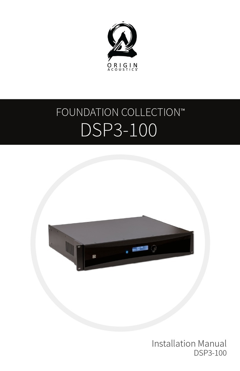
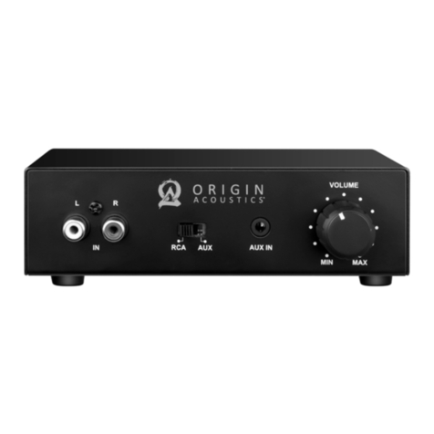
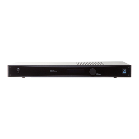
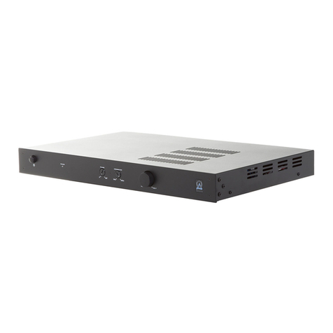
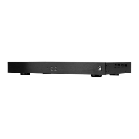
Origin Acoustics SUBA150 User manual

Installation Manual
SUBA150
Subwoofer Amplifier

1
844·674·4461
TECHSUPPORT@ORIGINACOUSTICS.COM WWW.ORIGINACOUSTICS.COM
SUBA150 INSTALLATION MANUAL
Table of Contents
Introduction 1
Getting Started 2
Specifications 3
Crossover Setting 4
Driving A Subwoofer 4
SUBA150 Phase Setting 5
Important Safety Instructions 5
Troubleshooting 7
Technical Assistance 8
Warranty 8
Two-Year Warranty 8
Requirements and Warranty Coverage 9
Return Process 9
Introduction
Congratulations and thank you for purchasing the SUBA150 class D
amplifier. This amplifier is designed as a stand alone compact ampli-
fier that allows custom home installation to have a powerful high ei-
ciency amplifications while fitting in small places. The SUBA150 comes
with a set of standard ears that allow the user to install it in a standard
single rack mount. Whether you are looking to power a subwoofer or a
tactile transducer, the SUBA150 is guaranteed to deliver.
The SUBA150 is powered by a switching regulated power supply PWM.
It delivers a steady and regulated output, delivering a linear amplifi-
cation to your load. Only through linear amplification do you get the
chance to deliver accuracy in amplifications.
The amplifier possesses an eicient switching power supply with
stability at 8 and 4 ohms. These amplifiers will deliver clean accurate
sound with massive damping factor.

2 3
844·674·4461
TECHSUPPORT@ORIGINACOUSTICS.COM WWW.ORIGINACOUSTICS.COM
SUBA150 INSTALLATION MANUAL
Getting Started
1. Audio sensing setting
2. Red = Amplifier is in auto mode
Green = Amplifier sensing signal: amplifier is on
3. Set with an SPL meter. See page 5
4. Set based on your application. See page 4
5. RCA input from a processor LFE
6. Set based on your input level and power rating of your load
7. High level input. 100 WRMS limit from receiver output
8. Amplified output to your subwoofer or your tactile
9. YOU MUST SET TO YOUR LOCAL POWER GRID LEVEL. NORMALLY
SHIPPED @ 110VAC
SubA150
110-120V~ 220-240V~
1
2
345
6 7 8
9
Specifications
Frequency Response 28Hz 175Hz
Power Line Voltage 110-120C~60Hz / 180 WATTS
Dimensions (HxWxD) 2” X 9” X 9”
Weight 4.5 Lbs
Finish Black
Input Sensitivity For
Full Output
240mVrms from le input with volume
control at 0dB, 90mVrms with volume control
fully clockwise.
Input Impedance 8.2 kilo-Ohm Line-level inputs, 32-Ohm
Speaker-level inputs
Internal System Gain 42dB from le input jack to speaker with
the Bass Level control at 0dB , 54dB with the
control fully clockwise.
Output Power into 4 ohm load 280 WRMS
Output Power into 8 ohm load 140 WRMS
WARNING
PLEASE READ THIS MANUAL BEFORE ATTEMPTING INSTALLATION

4 5
844·674·4461
TECHSUPPORT@ORIGINACOUSTICS.COM WWW.ORIGINACOUSTICS.COM
SUBA150 INSTALLATION MANUAL
Crossover Setting
Listed below are crossover settings in clock-like images. Each setting
shows the frequency response, 3dB down (half level)and system rec-
ommendation for each setting.
Driving A Subwoofer
If you are using the SubA150
to drive a subwoofer, then you
will need to set the crossover
below 100Hz. If you have a large
subwoofer such as 12” or 15” or
even 18”, then you will have a
great response with the cross-
over set to 12 o’clock setting or
minimum setting. For use with
a 10” or 8” subwoofer, you will
find 12 o’clock and 2 o’clock set-
ting to be the best range.
SUBA150 Phase Setting
If you are using the SubA150 to power a subwoofer, you will need to
set the time of arrival of your subwoofer frequencies with that of your
tower speakers. To do that with high accuracy, you will need to have
an SPL meter. There are many suppliers with such device. RadioShack
has one that works just fine. To set the phase, you will need to send a
continuous tone signal through the front speakers and the subwoofer
at the same time, rotate the phase to zero setting and place the me-
ter in the listening position. While the system is playing white noise
or 50-Hz tone, have someone read the meter. Then, rotate the phase
knob until the meter reads the highest reading. This will conclude the
setting. Document the position of your optimum phase and save it for
future references.
Important Safety Instructions
WARNING: To reduce the risk of fire or electric shock, do not expose
this apparatus to rain or moisture.
• Read these instructions.
• Keep these instructions.
• Heed all warnings.
• Follow all instructions.
• Do not use this apparatus near water.
• Clean only with dry cloth.
• Do not block any ventilation openings. Install in accordance with
the manufacturer’s instructions.
• Do not install near any heat sources such as radiators, heat regis-
ters, stoves, or other apparatus (including amplifiers) that produce
heat.
• Do not defeat the safety purpose of the polarized or grounding-type
plug. A polarized plug has two blades with one wider than the oth-
er. A grounding type plug has two blades and a third grounding
Please use this setting if con-
necting to a tactile transducer,
large subwoofer and large front
speakers.
Please use this setting if con-
necting to a tactile transducer, a
large subwoofer and small front
speakers.
Please use this setting if con-
necting to a small subwoofer
and small speakers.

6 7
844·674·4461
TECHSUPPORT@ORIGINACOUSTICS.COM WWW.ORIGINACOUSTICS.COM
SUBA150 INSTALLATION MANUAL
Symptom Possible cause Remedy
Sound is out
Amplifier(s) is not
connected to AC
Check out amplifier’s power
cord is well connected to live AC
outlet
The subwoofer
speaker(s) is not
connected to ampli-
fier(s) correctly
Check all the speaker wires are
connected to amplifier’s speaker
terminals
Amplifier’s fuse may
blow out
Turn the amplifier’s power o
first, and check the fuse is still in
good condition; If fuse is broken
and you have no spare one, find
your dealer for the replacement)
Amplifier does not
receive audio signal
from source
Make sure the audio cable(s) is
connected and the cable is good
Bad sound performance
Bad audio cable Check out all the audio cables to
make sure the cables are good
and connecting are good as well
The subwoofer
speaker is bad
Replace the bad subwoofer with
a good one, to verify if speaker
itself is the cause
The polarity of
speaker wire is
reversed
Check the polarity (+ / -) are
right, and correct them if they
are wrongly connected
Improper setting
of crossover, or has
chosen the wrong
mode
Try dierent crossover mode or
setting for the best result
Troubleshooting
prong. The wide blade or the third prong are provided for your
safety. If the provided plug does not fit into your outlet, consult an
electrician for replacement of the obsolete outlet.
• Protect the power cord from being walked on or pinched particu-
larly at plugs, convenience receptacles, and the point where they
exit from the apparatus.
• Only use attachments/accessories specified by the manufacturer.
• Use only with the cart, stand, tripod, bracket, or table specified by
the manufacturer, or sold with the apparatus. When a cart is used,
use caution when moving the cart/apparatus combination to avoid
injury from tip-over.
• Unplug this apparatus during lightning storms or when unused for
long periods of time.
• Refer all servicing to qualified service personnel. Servicing is re-
quired when the apparatus has been damaged in any way, such as
power-supply cord or plug is damaged, liquid has been spilled or
objects have fallen into the apparatus, the apparatus has been ex-
posed to rain or moisture, does not operate normally, or has been
dropped.
• The MAINS plug or an appliance coupler is used as the disconnect
device, so the disconnect device shall remain readily operable.
• This apparatus has been designed with Class-II construction and
must be connected to a mains socket outlet with a protective
earthing connection (the third grounding prong).
The lightning flash with arrowhead symbol, within an equi-
lateral triangle, is intended to alert the user to the presence
of uninsulated dangerous voltage within the product’s en-
closure that may be of suicient magnitude to constitute a
risk of electric shock to persons.
The exclamation point within an equilateral triangle is in-
tended to alert the user to the presence of important operat-
ing and maintenance (servicing) instructions in the literature
accompanying the appliance.
CAUTION
CAUTION: TO REDUC E THE RIS K OF
ELECTRICAL S HOCK.
DO NOT REMOVE COVER. NO US ER
S ERVICEABLE PARTS I NS IDE.
REFER S ERVIC ING TOQUALIFIED
S ERVICE PERSONNEL.

8 9
844·674·4461
TECHSUPPORT@ORIGINACOUSTICS.COM WWW.ORIGINACOUSTICS.COM
SUBA150 INSTALLATION MANUAL
This warranty may not be valid if the product was purchased through
an unauthorized dealer. This warranty only applies to the individual
that made the original purchase, and it cannot be applied to other pur-
chases. The purchaser must be prepared to provide proof of purchase
(receipt). This warranty will not be valid if the identifying number or
serial number has been removed, defaced, or altered.
This warranty does not cover the following:
• Accidental damage
• Damage caused by abuse or misuse
• Damage caused by attempted repairs/modifications by anyone
other than Origin Acoustics or an authorized dealer
• Damage caused by improper installation
• Normal wear, maintenance, and environmental issues
• Damage caused by voltage inputs in excess of the rated maximum
of the unit
• Damage inflicted during the return shipment
Before making any return attempts, it is required that you first contact
Origin Acoustics. Return product to Origin Acoustics or your dealer, ei-
ther in person or by mail. It’s preferable if the product is returned in the
original packaging. If this isn’t possible, the customer is responsible
for insuring the shipment for the full value of the product.
This warranty is in lieu of all other expressed or implied warranties.
Some states do not allow limitations on implied warranties, so this may
not apply depending on the customer’s location. (For more information,
see Magnuson-Moss Warranty Act.)
Origin Acoustics warrants to the original retail purchaser only that this
Origin Acoustics product will be free from defects in materials and
workmanship, provided the speaker was purchased from an Origin
Acoustics authorized dealer.
If the product is determined to be defective, it will be repaired or re-
placed at Origin Acoustics’ discretion. If the product must be replaced
yet it is no longer manufactured, it will be replaced with a model of
equal to or greater value that is the most similar to the original. If this
is the case, installing the replacement model may require mounting
modifications; Origin Acoustics will not be responsible for any such
related costs.
Return Process
Requirements and Warranty Coverage
Two-Year Warranty
Warranty
If you have any questions or concerns about installing or using this
product, you can reach us through one of the following methods:
Phone: (844) 674-4461
Hours of operation: 8:00am - 5:00pm (Pacific Time), Mon - Fri
Email: techsupport@originacoustics.com
If you are having technical trouble, please include the model number
and briefly explain what steps you took to resolve the problem in your
email, or be prepared to answer these questions over the phone. If you
are considering returning the product, it’s required that you contact
Origin Acoustics prior to any return attempts. This way we can deter-
mine if the issue can be resolved without returning the product, or if
needed we can provide instructions and support for the return process.
Technical Assistance

©2016 Origin Acoustics. All copyrighted, trademarked and
patented elements mentioned herein are the sole property of
Origin Acoustics.
Other manuals for SUBA150
1
Table of contents
Other Origin Acoustics Amplifier manuals

Origin Acoustics
Origin Acoustics SUBA500 User manual

Origin Acoustics
Origin Acoustics DSP3 Series User manual

Origin Acoustics
Origin Acoustics DSP3-700 User manual

Origin Acoustics
Origin Acoustics Crown CDi CDi1000 User manual

Origin Acoustics
Origin Acoustics Foundation PA15 User manual

Origin Acoustics
Origin Acoustics SUBA500 User manual

Origin Acoustics
Origin Acoustics DSP3-150 User manual

Origin Acoustics
Origin Acoustics A1250 User manual

Origin Acoustics
Origin Acoustics SUBA500 User manual

Origin Acoustics
Origin Acoustics A2150 User manual