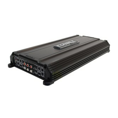
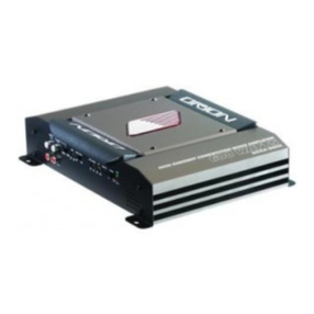
Orion XTREME 800.4 2 User manual

V
A3y
Z.lLZ-0068#lJBd
samedaioD
j.o
Aijiuej.
isav
3^1
J-O
suq
SSAS'SOA’OSt?
:xBd
OOgS
SOA'OSt-
:3uond
t?82S8
euozuv
'aduj
0
i
'is
Aai3>|3|/\|
'S
S£Z6
p04.BJodJO3U|
'S0uisnpu|
uopo
iiiiiHilllllHIIIII
#ORION

TABLE
OF
CONTENTS
INTRODUCTION
WARRANTY
SPECIFICATIONS
END
PANEL
LAYOUT
1
INPUT
CONIFURATIONS
1
4-CHANNEL
INPUT
CONFIGURATION
1
RCA
INPUT/COPY
1+2
1
INTERNAL
CROSSOVER
CONFIGURATION
1
INTELLI
Q
1
REMOTE
GAIN
OPERATION
1
INPUT
GAIN
1
POWER
CONNECTIONS
SPEAKER
CONNECTIONS
INSTALLATION
TESTING
THE
SYSTEM
ADJUSTING
THE
SOUND
OF
THE
SYSTEM
TROUBLESHOOTING
TIPS
32
AUTOSOUND
2000
TROUBLESHOOTING
TIPS
34

INTRODUCTION
Thank
you
for
your
purchase
of
ORION'S
XTREME
amplifier.
Each
ORION
amplifier
is
designed
to
be
the
leader
in
its
class
offering
the
most
power,
advanced
features
and
ease
of
use.
The
ORION
XTREME
amplifiers
are
designed
as
the
best
car
audio
amplifier
money
can
buy.
Listed
below
are
the
features
of
the
XTREME
800.4.
•
XTREME
800.4
-
93.75
watts
per
channel,
4-channel
amplifier
with
fully
variable
low-pass
crossovers
from
45Hz
to
5khz.
The
high-
pass
crossover
is
continuously
variable
from
10Hz
to
10kHz.
The
XTREME
800.4
has
the
INTELLiQ
subwoofer
optimizing
circuitry
and
dual
remote
gain
capability.
The
XTREME
600.4
is
capable
of
6,
5,
4,
3,
or
2
channel
operation.
NOTE:
The
installation
of
all
ORION
XTREME
amplifiers
will
determine
the
overall
performance
result.
Improper
installation
will
not
only
limit
the
performance
of
your
ORION
system
but
also
potentially
compromise
the
reliability
of
this
amplifier.
To
ensure
proper
sonic
results
and
component
reliability,
please
refer
to
your
Authorized
ORION
dealer
for
installation
assistance
or
advice.
If
you
decide
to
perform
the
installation
yourself,
read
the
entire
installation
section
of
this
manual
before
beginning
the
installation.
page
4
ABOUT
THIS
MANUAL
This
manual
is
divided
into
different
sections
for
different
needs.
Whether
you
are
the
owner,
salesperson
or
installer,
we
have
devoted
sections
of
this
manual
to
answer
your
questions.
We,
at
ORION,
strive
to
give
you
the
latest
up
to
date
information
about
our
products.
What
we
cannot
give
you
is
personal
installation
or
technical
experience.
If
you
have
questions
regarding
the
installation
or
the
setup
or
tuning
of
this
product,
please
refer
to
your
nearest
Authorized
ORION
Dealer
for
assistance.
Additionally,
you
can
call
ORION'S
Technical
Support
Hotline
at
(480)705-5600
for
assistance.
PRACTICE
SAFE
SOUND
Continuous
exposure
to
sound
pressure
levels
over
lOOdB
may
cause
permanent
hearing
loss.
High
powered
automotive
sound
systems
can
generate
sound
pressure
levels
in
excess
of
130dB.
When
playing
your
system
at
high
levels,
please
use
hearing
protection
and
avoid
long
term
exposure.
RECORD
YOUR
SERIAL
NUMBER
AND
DATE:
Model:
Serial
Number:
Date
of
Purchase:
Company
Purchased
From:
pages

WHAT'S
IN
THE
BOX
(1)
XTREME
amplifier
(1)
4
gauge
power
and
ground
connector
(1)
12
gauge
speaker
and
remote
connector
(4)
#8
self-tapping
black
Phillips
pan
head
screws
(1)
XTREME
installation
and
operation
manual
NOTE:
The
XTR
amplifier
handles
are
an
optional
accessory
available
at
your
local
authorized
ORION
dealer.
page
6
WARRANTV
ORION
Industries
Inc.
warrants
this
product
to
be
free
from
defects
in
material
and
workmanship
under
the
following
terms:
Parts
and
Labor
are
warranted
for
a
period
of
3
years
IF:
a.
The
product
is
purchased
from
an
Authorized
ORION
Dealer
b.
The
product
is
installed
by
an
Authorized
ORION
Dealer
Parts
and
Labor
are
warranted
for
a
period
of
1
year
IF:
a.
The
product
is
purchased
from
an
Authorized
ORION
Dealer
b.
The
product
is
NOT
installed
by
an
Authorized
ORION
Dealer
Parts
and
Labor
are
warranted
for
a
period
of
90
days
IF:
a.
The
product
is
NOT
purchased
from
an
Authorized
ORION
Dealer
If
you
are
uncertain
as
to
whether
your
dealer
is
authorized,
please
contact
ORION
at
(480)
705-5600.
In
countries
other
than
the
USA,
each
distributor
warrants
the
ORION
product
it
sells.
The
Following
conditions
and
situations
are
NOT
covered
by
this
warranty:
Any
product
on
which
the
serial
number
has
been
defaced,
modified
or
removed
Damage
or
malfunction
resulting
from:
a.
Accident,
misuse,
abuse,
unauthorized
modification
or
failure
to
follow
the
instructions
provided
with
this
product
b.
Repair
by
anyone
NOT
authorized
by
ORION.
c.
Damage
due
to
shipping
(these
claims
must
be
presented
to
the
freight
carrier)
d.
Removal
or
installation
of
this
product.
e.
Any
failure
that
has
NOT
been
caused
by
a
defect
in
material
or
workmanship.
This
warranty
is
in
effect
for
the
original
purchaser
only.
ORION
will
pay
for
labor
and
material
expense
for
covered
items.
ORION
does
not
cover
removal
or
installation
charges,
payment
of
shipping
charges
to
ORION,
payment
of
OUT-OF-WARRANTY
shippinq
charges,
or
damage
to
other
property
caused
by
any
defects
in
this
product.
page?

For
all
warranty
and
non-warranty
service
issues,
please
refer
to
your
nearest
Authorized
ORION
Dealer
for
assistance.
If
you
require
additional
information
or
assistance
regarding
service
repair
issues,
please
call
(480)
705-5600.
Exclusion
1.
This
warranty
is
in
lieu
of
all
other
warranties
expressed
of
implied
2.
In
no
event
will
ORION
be
liable
for
any
consequential
damages
resulting
from
the
use
of
this
product
or
any
defect
of
this
product.
This
Warranty
gives
you
specific
legal
rights
and
you
may
also
have
other
rights
which
vary
from
state
to
state.
SAVE
VOUR
RECIEPT!
pages
SPECIFICATIONS
Amplifier
XTREME
800.4
Front
Channels
XTREME
800.4
Rear
Channels
Power
output
4
Q
stereo
(watts)'
100x2
100x2
100x2,
400
X
1
100x2,
400
X
1
Power
output
2
£2
stereo
(watts)^
200x2
200x2
Power
output
4
£2
mono
(watts)'
400
X
1
400
X
1
Distortion
all
channels
driven
(from
20Hz
to
20kHz)
<0.1%
THD
<0.1%
THD
Frequency
Response
20Hz
to
20kHz
±0.25dB
20Hz
to
20kHz
±0.25dB
Linear
Bandwidth
GHz
to
50kHz
±3dB
6Hz
to
50kHz
±3dB
Signal-to-noise
ratio
full
bandwidth
@
rated
output
power
>100dB
>100dB
Damping
factor
@
output
connector
@
full
bandwidth
>400
at
output
connector
>400
at
output
connector
Slew
Rate
>30Vns
>30V|.ts
Input
Sensitivity^
200
mV
to
5
Vrms
200
mV
to
5
Vrms
Input
Impedance
20
k
ohm
20
k
ohm
Fuse
Type
(3)
20
Amo
ATC
(3)
20
Amp
ATC
page
9

Crossover^
XTREME
800.4
Front
Channels
XTREME
800.4
Rear
Channels
Low-Pass
Crossover
Continuously
variable
Continuously
variable
Low-Pass
Frequency
Range
45Hz
to
5kHz
45Hz
to
5kHz
High-Pass
Crossover
Continuously
variable
Continuously
variable
High-Pass
Frequency
Range
10Hz
to
10kHz
45Hz
to
5kHz
High-Pass
INTELLiQ
Range
OdB
to
lOdB
of
Boost
n/a
General
Dimensions
18"Lx
10.25"Wx2.25"H
(457mm
x
260mm
x
57mm)
18"Lx
10.25"Wx
2.25"H
(457mm
x
260mm
x
57mm)
’
All
channels
driven,
continuous
rated
4Q
load,
20Hz
to
20,000Hz,
>0.1%
THD,
per
input
voltage
at
13.8VDC.
2
All
channels
driven,
continuous
rated
2Q
load,
20Hz
to
20,000Hz,
>0.1%
THD,
per
input
voltage
at
13.8VDC.
^
XTREME
amplifiers
are
designed
to
accept
full
9
Volts
RMS
input
when
set
to
the
minimum
gain
position.
'*
All
crossovers
are
with
a
slope
rate
of
12dB/octave
and
a
"Q"
of
.0707.
page
10
END
PANEL
LAYOUT
1.
Power
LED
-
lights
up
when
the
amplifier
is
on
2.
Low-pass
crossover
frequency
control-adjusts
the
front
channel
low-pass
crossover
frequency
(page
14)
3.
Low-pass
crossover
switch-activates
the
front
channel
low-pass
crossover
(page
14)
4.
INTELLiQ
gain-adjusts
the
level
of
INTELLiQ
from
OdB
to
lOdB
of
boost
(page
17)
5.
High-pass
crossover
"xIO"
switch-changes
the
high-pass
crossover
frequency
range
(page
15)
6.
High-pass
crossover
frequency
control-adjusts
the
front
channel
high-pass
crossover
frequency
(page
15)
7.
High-pass
crossover
switch-activates
the
front
channel
high-pass
crossover
(page
15)
8.
Front
Gain
Control
-
continuously
adjusts
from
200mV
to
5Vrms
for
full
power
output
(page
19)
9.
Front
Input
Configuration
Switch
-
determines
the
input
configuration
for
the
front
channels
(page
12)
10.
Front
RCA
Inputs-
accepts
RCA
input
from
a
source
unit,
pream¬
plifier
or
equalizer
for
the
front
channels
11.
Rear
RCA
Inputs-
accepts
RCA
input
from
a
source
unit,
preampli¬
fier
or
equalizer
for
the
rear
channels
12.
2
RCA
IN
/
4
RCA
IN
Switch
-
configures
the
amplifier
for
two
or
four
RCA
inputs
(page
12)
13.
Rear
Output
Configuration
Switch
-
determines
the
output
configuration
for
the
rear
channels
(page
12)
14.
Rear
Crossover
Control
-
adjusts
the
frequency
for
the
rear
channels
(page
14)
15.
RCA
INPUT
/
COPY
1+2
button
configures
rear
channels
for
direct
input
or
output
of
front
channel
crossover
and
gain
(page
13)
16.
Rear
Gain
Control
-
continuously
adjusts
from
200mV
to
5Vrms
for
full
power
output
(page
19)
1
2
3
4
5
6
7
8
9
10
11
12
13
14
17.
Rear
Crossover
Switch
-
configures
the
rear
channel
for
high-
pass,
low-pass
or
full
range
operation
(page
13)
18.
REM
Remote
Turn-on
Input
-
turns
on
the
amplifier
when
fed
12
V+
(page
20)
19.
Front
speaker
output-
allows
up
to
12
gauge
speaker
wire
(page
21
)
20.
Rear
speaker
output-
allows
up
to
12
gauge
speaker
wire
(page
21
)
21.
Remote
Gain-allows
dashboard
control
of
the
amplifier
output
level
(page
19)
22.
Fuse
-
protects
the
amplifier
from
over
current
situations
23.
Power
Connections
-
allow
up
to
4
gauge
power
and
ground
cables
(page
20)
page
11

OUTPUT
CONFIGURATIONS
Three
position
switches
determine
output
configuration
for
the
XTREME
amplifiers.
Each
stereo
pair
of
channels
can
be
configured
in
either
stereo,
summed-bridged
and
bridged-mono.
The
switch
or
switches
are
located
on
he
outermost
edge
of
the
amplifier.
D
ST
/
/
IhHOIUO
(R)
SUM
(L*R)
When
the
switch
is
in
the
left
position,
the
output
channels
are
configured
for
stereo
operation.
ST
I/
ImOHO
(R)
SUM
(L*R}
When
the
switch
is
in
the
center
position,
the
output
channels
are
configured
for
summed
mono
operation
by
mixing
the
left
and
right
input
signals
together.
Use
this
setting
when
using
a
pair
of
RCA
inputs.
stI/
Immuo
(R)
SUM
(l.*R)
When
the
switch
is
in
the
right
position,
the
output
channels
are
configured
for
a
single
bridged
output
using
a
single
RCA
input.
To
determine
which
RCA
to
use,
refer
to
the
marking
in
parenthesis.
For
the
front
outputs,
the
Left
RCA
input
is
used.
For
the
rear
outputs,
the
Right
RCA
input
is
used.
4-CHANNEL
AMPLIFIER
INPUT
CONFIGURATIONS
2
RCA
IN
4
RCA
IN
2
RCA
IN
4
RCA
IN
The
2
RCA
IN
/
4
RCA
IN
switch
routes
RCA
input
from
the
front
RCA
inputs
to
the
rear
section
of
the
amplifier.
This
allows
the
XTREME
4-channel
amplifier
to
utilize
a
single
set
of
RCAs
to
feed
signal
to
both
the
front
and
rear
channels
of
the
amplifier.
When
the
switch
is
in
disengaged,
signal
from
the
front
RCA
input
is
routed
to
the
rear
RCA
inputs.
NOTE:
In
this
configuration,
the
rear
RCA
inputs
can
be
routed
to
another
amplifier.
The
signal
leaving
the
amplifier
is
a
copy
of
the
incoming
signal.
When
the
switch
is
disengaged,
front
and
rear
RCA
inputs
are
independent.
This
allows
a
source
unit
with
an
internal
fader
to
fade
between
the
front
and
rear
outputs.
page
12
RCA
INPUT
/
COPY
1+2
2
RCA
IN
sm
4
RCA
m
■
RCA
INPUT
M
COPY
1+2
■
sr
f
Wi/il
rP)
2
l?C4
m
m
4RCAm
■
RCA
INPUT
m
COPY
1+2
■
m
I
^
’
!
!
I
!
‘
i
‘
■
7
[
(I
tP,
The
RCA
Input
/
COPY
1+2
push
button
switch
configures
the
input
for
Channels
3
&
4.
The
feature
allows
the
more
advanced
crossover
features
of
the
front
channels
to
be
routed
to
both
the
front
and
rear
channels.
Configured
in
this
manner,
INTELLiQ
is
now
available
on
all
channels
of
the
amplifier
as
well
as
bandpass
crossovers
for
midbass
and
midrange
speakers.
When
the
switch
is
disengaged,
the
REAR
INPUT
RCA
input
feeds
channels
3+4.
When
the
switch
is
engaged,
channels
3
&
4
receive
input
signal
from
the
output
of
channels
1
&
2
after
the
crossover
output.
When
the
switch
is
in
engaged,
signal
from
the
front
RCA
input
is
routed
to
the
rear
RCA
inputs.
The
front
gain
control
controls
the
level
of
the
entire
amplifier.
The
rear
gain
controls
are
deactiviated.
REAR
INTERNAL
CROSSOVER
CONFIGURATION
The
XTREME
600.4
use
multi-position
switches
to
determine
the
rear
crossover
configuration.
The
multi-position
switch
is
located
on
the
adjustment
side
of
the
amplifier.
Listed
below
are
the
switch
positions
and
their
respective
crossover
configurations.
When
the
switch
is
in
the
"OFF"
position,
the
crossover
section
of
the
amplifier
is
bypassed.
Amplifier
output
is
full
range.
6
OOH
2
5kHz-
[
I
I
I
OFF
HP
LP
4SHz
When
the
switch
is
in
the
center
position,
the
crossover
is
configured
for
high-pass
operation.
The
rear
channels
of
the
XTREME
600.4
are
continuously
variable
from
45Flz
to
SkFIz.
page
13

REAR
INTERNAL
CROSSOVER
CONFIGURATION
600Hz
5kHz,
S_5;/
I
I
I
OFF
HP
LP
45Hz
When
the
switch
is
in
the
right
position,
the
crossover
is
configured
for
low-pass
operation.
The
rear
channels
of
the
XTREME
600.4
are
continuously
variable
from
45Hz
to
5kHz.
FRONT
INTERNAL
CROSSOVER
CONFIGURATION
The
front
channels
of
the
XTREME
600.4
can
be
configured
for
either
high-pass,
low-pass
or
bandpass
operation.
INTELLiQ
is
a
feature
of
the
amplifier
that
maximizes
the
performance
of
any
subwoofer
system.
INTELLiQ
is
the
one
feature
that
separates
ORION
amplifiers
from
the
compitition.
FRONT_CHANNEL_ADJUST!VIENT^^__
/
~
600Hz
5kHz
When
the
puch
button
switch
is
in
the
"off"
position,
the
low-pass
crossover
is
bypassed.
LPON
»
LP
OFF
m
FRONT
CHANNEL
ADJUSTMENTS
When
the
push
button
switch
is
in
the
"on"
position,
the
iow-pass
crossover
is
activated.
The
crosso
ver
frequency
range
is
from
45Hz
to
5kHz.
There
are
additional
reference
points
at
85Hz,
2.5kHz
and
3.5kHz
respectively.
page
14
FRONT
INTERNAL
CROSSOVER
CONFIGURATION
FRONT
CHANNEL
ADJUSTMENTS
When
the
puch
button
switch
is
in
the
"off"
position,
the
high-pass
crossover
is
bypassed.
When
the
push
button
switch
is
in
the
"on"
position
and
the
"xIO"
button
is
on
the
on
position,
the
high-pass
crossover
is
activated
in
the
"high"
range.
The
crosso
ver
frequency
range
is
from
100Hz
tolOkHz.
There
are
four
corner
frequencies
at
100Hz,
350Hz,
1,200Hz
and
10kHz.
This
range
is
usefull
when
used
with
smaller
diameter
midrange
and
tweeter
speakers.
When
the
push
button
switch
is
in
the
"on"
position
and
the
"xIO"
button
is
on
the
off
position,
the
high-pass
crossover
is
activated.
The
crossover
frequency
range
is
from
10Hz
tolkHz.
There
are
four
corner
frequencies
at
10Hz,
35Hz,
120Hz
and
1kHz.
This
range
is
usefull
when
used
with
iarger
diameter
midrange
and
midbass
speakers.
Additionaily,
this
can
also
be
used
as
a
"subsonic
filter"
to
prevent
potentially
damaging
low-frequency
from
getting
to
your
subwoofer
(See
INTELLi
Q
section
on
page
16.)
page
15

FINE
TUNING
INTERNAL
CROSSOVER
2.S00HZ
eOOHx\5§€Hx
3,500Hz
175Hk
45Ha!
85Hz
Low
Pass
Crossover
The
low-pass
crossover
on
the
front
channels
and
the
rear
crossover
is
continuously
adjustable
from
45Hz
tro
5kHz.
There
are
three
markings
surrounding
the
crossover
pot
that
designate
85Hz
2,500Hz
and
3,500Hz
respectively.
High
Pass
Crossover
1,200
Hz
10
kHz
120Hz
1kHz
350
Hz
100
Hz
When
the
high-pass
crossover
push
button
switch
is
in
the
"on"
position
and
the
"xIO"
button
is
on
the
on
position,
the
high-pass
crossover
is
activated
in
the
"high"
range.
The
crossover
frequency
range
is
from
100Hz
tolOkHz.
There
are
four
corner
frequencies
at
100Hz,
350Hz,
1,200Hz
and
10kHz.
This
range
is
usefull
when
used
with
smaller
diameter
midrange
and
tweeter
speakers.
When
the
high-pass
crossover
push
button
switch
is
in
the
"on"
position
and
the
"xIO"
button
is
on
the
off
position,
the
high-pass
crossover
is
activated.
The
crossover
frequency
range
is
from
10Hz
tolkHz.
There
are
four
corner
frequencies
at
10Hz,
35Hz,
120Hz
and
1kHz.
This
range
is
usefull
when
used
with
larger
diameter
midrange
and
midbass
speakers.
Additionally,
this
can
also
be
used
as
a
"subsonic
filter"
to
prevent
potentially
damaging
low-frequency
from
getting
to
your
subwoofer.
page
16
INTELLI
Q
FRONT
CHANNEL
ADJUSTMENTS
In
the
world
of
"me
too
features,"
Orion
has
developed
the
INTELLi
Q
circuit
that
makes
a
real
differ¬
ence
in
your
automotive
listening
experience.
INTELLi
Q
(INTELL\gent\y
integrated
Q
adjustment)
is
actually
an
infinitely
variable
"Q"
adjustment
found
on
the
high-pass
crossover
of
new
XTREME
and
HCCA
"Type
R"
power
amplifiers.
By
changing
the
"Q"
of
the
high-pass
from
the
industry
standard
0.707
to
any
"Q"
value
between
0.707
and
3.5
(Figure
1
),
the
high-pass
filters
essentially
becomes
two
filters:
a
single
band
parametric
equalizer
and
a
subsonic
filter.
6c/B
lOdB
By
increasing
the
"Q"
value
from
0.707
to
3.5,
the
output
is
boosted
up
to
lOdB
at
the
high-pass
crossover
frequency.
The
end-panel
display
is
clearly
marked
in
3dB
boost
steps.
Unlike
other
manufac¬
turers
"subsonic
filters,"
adjusting
the
INTELLi
Q's
high-pass
crossover
frequency
easily
performed
turning
the
crossover
pot
located
directly
to
the
right
of
the
"Q"
adjustment
(Figure
2).
The
high-pass
crossover
is
continuously
variable
from
10Hz
to
1kHz
or
100Hz
to
10kHz
via
a
xIO
frequency
selector.
By
correctly
using
the
INTELLi
Q,
you
can
increase
low
frequency
output
by
as
much
as
lOdB!
Boosting
the
lower
bass
frequency
does
not
come
without
trade-offs.
As
anyone
knows,
one
of
the
greatest
potentials
for
woofer
damage
is
caused
by
over
excursion.
Excursion
is
the
forward
and
backward
movement
of
a
woofer.
When
the
signal
to
the
woofer
is
incorrectly
boosted,
the
woofer
is
required
to
move
more
than
is
capable.
For
reference,
a
6dB
of
boost
requires
a
woofer
to
quadruple
its
excursion
to
match
the
input
signal.
Ordinary
bass
boost
equalizers
boost
without
protection.
Without
any
protection,
potential
for
damage
is
high.
The
difference
of
INTELLi
Q
What
makes
the
INTELLi
Q
different
from
all
other
equalizers
or
sub-sonic
filters
is
that
it
can
boost
lower
frequencies
the
woofer
can
produce
by
lOdB
while
preventing
over
excursion
that
can
damage
the
woofer.
The
result
is
your
woofer
with
the
loudest
low
bass
it
can
produce
reliably.
Here's
how
to
use
it.
page
17

INTELLI
Q
Setting
up
and
using
INTELLi
Q
1.
The
first
step
to
using
the
INTELLi
Q
is
to
install
the
amplifier.
Seriously,
basic
installation
techniques
for
new
XTREME
amplifiers
remain
unchanged.
Set
the
low-pass
crossover
as
you
would
in
"normal"
installations.
(Normal
Orion
of
course.)
2.
Determine
which
type
of
enclosure
you
are
using.
Refer
to
the
table
below
for
tuning
assistance.
For
example:
for
vented
enclosures,
set
the
high-pass
crossover
to
the
tuning
frequency
(port
frequency)
of
the
enclosure.
If
you
have
a
woofer
such
as
the
new
HCCA
woofers
up
to
lOdB
of
boost
can
be
used.
For
woofers
of
lesser
excursion
capability,
it
is
recommended
to
use
up
to
6dB
of
boost
only.
3.
For
RTA
tuning,
start
the
INTELLi
Q
boost
setting
at
OdB.
Using
pink
noise,
slowly
increase
the
Q
adjustment
until
the
desired
frequency
response
is
achieved.
In
situations
where
you
are
require
more
boost
than
is
recommended,
you
can
lower
the
crossover
frequency
to
get
a
similar
desired
effect.
4.
For
tuning
by
ear,
start
the
INTELLi
Q
boost
setting
at
OdB.
Using
music
the
high-energy
low
frequency
content,
slowly
increase
the
Q
adjustment
until
the
desired
sonic
performance
in
achieved.
In
situations
where
you
are
require
more
boost
than
is
recommended,
you
can
lower
the
crossover
frequency
to
get
a
similar
desired
effect
Boost
Levels
OdB
+3dB
+6dB
-
+10dB
Enclosure
Type
:
Infinite
Baffle
Acceptable
No
Problems
Tune
above
Fs
of
woofer
High
X-Max
Drivers
Tune
above
Fs
of
woofer
Not
Recommended
Not
Recommended
Sealed
Acceptable
No
Problems
Tune
above
Fs
of
woofer
Acceptable
No
Problems
Tune
above
Fs
of
woofer
High
X-Max
Drivers
Tune
above
Fs
of
woofer
Not
Recommended
Vented
Acceptable
No
Problems
Tune
to
port
frequency
Acceptable
No
Problems
Tune
to
port
frequency
Acceptable
No
Problems
Tune
to
port
frequency
High
X-Max
Drivers
Tune
to
port
frequency
Sealed
Bandpass
Acceptable
No
Problems
Tune
above
Fs
of
woofer
Acceptable
No
Problems
Tune
above
Fs
of
woofer
High
X-Max
Drivers
Tune
above
Fs
of
woofer
Not
Recommended
Vented
Bandpass
Acceptable
No
Problems
Tune
to
port
frequency
Acceptable
No
Problems
Tune
to
port
frequency
Acceptable
No
Problems
Tune
to
port
frequency
High
X-Max
Drivers
Tune
to
port
frequency
Aperiodic
Set
crossover
to
Fs
of
woofer_
Set
crossover
to
Fs
of
woofer
Set
crossover
to
Fs
of
woofer
Not
Recommended
page
18
REMOTE
GAIN
REMOTE
REM
REM
GAIN
GAIN
The
remote
gain
port
allows
remote,
user
control
over
the
output
of
the
amplifier.
When
used
on
a
subwoofer
amplifier,
the
remote
gain
allows
you
to
change
the
bass
level
for
different
music
styles,
driving
conditions,
or
sonic
preferences.
Unlike
other
designs,
Orion
allows
remote
access
to
the
level
of
the
amplifier
via
a
digital
micro-controller
and
electronic
volume
that
does
not
interfere
with
the
sonic
signal
chain.
The
result
is
a
clean
clear
control
of
the
level
of
the
amplifier
that
is
unaffected
by
noise.
The
XTREME
600.4
has
two
remote
gain
ports.
This
allows
for
individual
control
of
either
the
front
or
rear
channels.
One
RGC-1
can
be
used
to
control
the
level
of
the
front
channels
and
another
RGC-1
can
be
used
to
control
the
output
level
of
the
rear
channels.
An
example
benefit
of
this
is
having
the
front
channels
in
bandpass
mode
for
midbass
and
the
rear
channels
In
low-pass
mode
for
subwoofers.
Using
two
RGC-1
would
give
the
driver
the
ability
to
control
the
level
of
both
the
midbass
and
subwoofers
for
easy
optimal
tuning.
To
utilize
this
function
simply
plug-in
a
RGC-1
into
either
the
front
or
rear
gain
ports.
The
RGC-1
is
available
from
your
authorized
ORION
dealer.
SIGNAL
INPUT
AND
OUTPUT
LEVEL
CONTROLS
XTREME
amplifiers
have
separate
front
and
rear
level
adjustments.
The
input
sensitivity
of
these
adjustments
range
from
200mv
up
to
SVrms
on
the
RCA
inputs.
This
allows
easy
integration
from
any
source
unit
either
with
RCA
outputs
or
speaker
outputs.
Refer
to
the
Testing
the
System
and
the
Adjusting
the
Sound
of
the
System
sections
for
detailed
instructions
on
setting
up
the
level
controls.
<
!
:
I
!.
.
^
\
!
I
page
19

POWER
CONNECTIONS
•
Minimum
8
gauge
power
and
ground
cable
is
recommended
for
acceptable
performance
•
4
gauge
power
and
ground
cable
is
recommended
for
optimal
performance
•
Fuse
power
wire
less
than
18"
from
battery
•
Ground
amplifier
to
a
good
chassis
ground
as
close
as
possible
to
the
amplifier
•
Add
extra
ground
wire
between
the
negative
terminal
of
the
battery
and
the
chassis
TUNING
NOTE:
The
addition
of
a
ground
wire
from
the
battery
to
the
chassis
of
the
vehicle
improves
the
ability
of
the
battery
to
supply
power
to
the
amplifier.
This
helps
especially
in
newer
vehicles,
where
the
current
delivery
of
the
factory
electrical
system
was
designed
only
to
accommodate
electronics
supplied
by
the
auto
manufacturer.
page
20
SPEAKER
CONNECTIONS
4-CHANNEL
STEREO
CONFIGURATION
•
Front
and
rear
channel
lowest
recom¬
mended
impedance
is
2
Ohms
stereo
•
Crossover,
output
and
gain
configurations
are
independently
adjustable
between
the
front
and
rear
channels
•
2-channel
or
4-channel
input
can
be
used
for
this
configuration.
For
source
unit
fading,
use
the
4-channel
input
mode
(page
11
)
•
Front
outputs
can
be
configured
for
high-
pass,
low-pass
or
bandpass
operation
(page
13
)
•
Front
channels
equipped
with
INTELLiQ
subwoofer
optimization
circuitry
(page
16)
•
Rear
outputs
can
be
configured
for
high-
pass,
low-pass
or
full
range
operatlon(page
13)
•
Front
and
rear
outputs
can
be
configured
for
either
stereo
operation
or
summed
for
subwoofer
applications
(page
11)
2
Ohm
Minimum
2
Ohm
Minimum
page
21

SPEAKER
CONNECTIONS
3-CHANNEL
STEREO/BRIDGED
CONFIGURATION
•
Front
channels
are
configured
for
2-channel
stereo
operation
(page
11)
•
Front
channel
lowest
recommended
impedance
is
2
Ohms
stereo
•
Rear
channels
are
configured
for
a
single
channel
bridged
output
(page
11)
•
Rear
channel
lowest
recommended
impedance
is
4
Ohms
•
Crossover,
output
and
gain
configurations
are
indepen¬
dently
adjustable
between
the
front
and
rear
channels
•
2-channel
or
4-channel
input
can
be
used
for
this
configuration.
For
source
unit
fading,
use
the
4-channel
input
mode
(page
11)
•
Front
and
rear
outputs
can
be
configured
for
high-pass,
low-pass
or
full
range
operation
(page
12)
•
Front
outputs
can
be
configured
for
either
stereo
or
summed
stereo
operation
(page
11)
•
Rear
outputs
can
be
configured
for
summed
bridged
or
single
channel
bridged
operation
for
subwoofer
applications
(page
11)
page
22
SPEAKER
CONNECTIONS
TWO-CHANNEL
BRIDGED
CONFIGURATION
•
Front
and
rear
channels
are
configured
for
bridged
2-
channel
operation
•
Lowest
recommended
impedance
for
both
front
and
rear
channels
is
4
Ohms
•
Crossover
and
gain
configurations
are
independently
adjustable
between
the
front
and
rear
channels
•
2-channel
operation
is
recommended
for
this
operational
mode
•
Front
and
rear
outputs
can
be
configured
for
high-pass,
low-pass
or
full
range
operation
(page
12)
•
Front
and
rear
outputs
can
be
configured
for
stereo
(front
channels
will
have
right
output,
rear
channels
will
have
left
output
or
summed
2-channel
operation
(page
11)
2
Ohm
Minimum
2
Ohm
Minimum
page
23

SPEAKER
CONNECTIONS
TRI-MODE
6-CHANNEL
CONFIGURATION
•
Lowest
recommended
impedance
is
2
Ohm
stereo
and
4
Ohm
bridged
mono
•
Front
and
rear
outputs
must
be
set
for
full
range
operation
(page
12)
•
Front
and
rear
outputs
must
be
configured
for
stereo
operation
(page
11)
•
Passive
crossover
frequencies
must
not
overlap.
WARNING!
Failure
to
do
so
may
result
in
damage
to
the
amplifier
-OO
4
Ohm
Minimum
4
Ohm
Minimum
page
24
INSTALLATION
TIPS
The
installation
of
all
ORION
components
will
determine
the
overall
performance
result.
Improper
installation
will
not
only
limit
the
perfor¬
mance
of
your
ORION
system
but
also
potentially
compromise
the
reliability
of
this
amplifier.
To
ensure
proper
sonic
results
and
component
reliability,
please
refer
to
your
Authorized
ORION
dealer
for
installation
assistance
or
advice.
If
you
decide
to
perform
the
installation
yourself,
read
the
entire
installation
section
of
this
manual
before
beginning
installation.
TOOLS
OF
THE
TRADE
Listed
are
the
majority
of
the
tools
required
to
perform
the
installation,
of
these
tools
are
necessities.
Some
make
the
job
much
easier.
•
marking
pen
•
electric
drill
with
assorted
drill
bits
•
utility
knife
•
Phillips
and
flat
blade
screw
drivers
•
pliers
(standard
and
needle
nose)
•
wire
brush
or
sandpaper
for
chassis
grounding
•
solder
iron
and
solder
Having
the
proper
tools
will
make
the
installation
much
easier.
Some
•
heat
shrink
tubing
•
nylon
tie
straps
•
volt-ohm
meter
(optional)
•
wire
cutters
•
wire
crimpers
•
wire
strippers
page
25

MOUNTING
THE
XTR
AMPLIFIER
The
XTR
amplifiers
have
a
unique
mounting
system
that
can
be
con¬
figured
for
different
install
situations.
By
placing
the
removable
mounting
rails
in
the
"in"
or
"out"
positions
the
look
of
the
amplifier
mounting
can
be
changed
to
suit
personal
tastes
or
installation
re¬
quirements.
In
the
"in"
position,
you
will
not
see
the
amplifier
mounting
screws
and
the
amp
will
"float"
above
the
mounting
screws.
The
amp
can
also
be
mounted
in
a
"standard"
manner
using
the
"out"
position.
FIGURE
A
FIGURE
B
XTR800.4
-
18"(457mm)
FIGURE
A:
This
figure
shows
the
mounting
feet
of
the
amplifier
in
the
"in"
position.
To
mount
the
am¬
plifier
in
this
manner
you
must
mount
just
the
two
feet
to
the
mounting
surface
before
screwing
them
to
the
amp.
The
distance
needed
between
the
verti¬
cal
sides
of
each
foot
is
noted
in
the
figure
to
the
left.
Simply
measure
the
distance,
mount
the
feet,
then
mount
the
amplifier
to
the
feet.
FIGURE
B:
This
figure
shows
the
mounting
feet
in
the
"out"
postion.
This
method
can
be
accomplished
by
using
the
same
procedure
as
above
or
by
simply
mounting
the
feet
to
the
amplifier
and
mounting
the
amplifier
to
the
surface
as
you
would
a
"nor¬
mal"
amp.
page
26
CHOOSING
MOUNTING
LOCATIONS
The
location
of
your
XTREME
amplifier
will
depend
on
several
important
issues.
Due
to
the
low
profile
size
of
the
XTREME
amplifiers,
there
are
many
possible
installation
locations
that
will
yield
satisfactory
amplifier
performance.
Always
mount
the
amplifier
in
a
place
that
protects
the
amplifier
from
the
elements.
In
addition,
mount
the
amplifier
on
a
stable,
flat
mounting
surface.
As
with
any
amplifier,
there
are
several
possible
mounting
locations
and
configurations
that
can
be
optimal.
We
will
cover
the
most
obvious
of
situations.
PASSENGER
COMPARTMENT
If
you
are
going
to
mount
the
amplifier
in
the
passenger
compartment,
make
sure
you
have
adequate
room
for
ventilation.
XTREME
amplifiers
have
been
designed
to
make
possible
under
seat
mounting.
When
mounting
your
amplifier
under
a
seat
or
similar
area,
keep
a
minimum
of
1
of
clearance
around
the
amplifier
for
adequate
cooling.
TRUNK
COMPARTMENT
Mounting
XTREME
amplifier
in
the
trunk
provides
excellent
performance
as
long
as
you
do
not
mount
the
amplifier
upside
down
or
restrict
the
airflow
around
the
heatsink
of
the
amplifier.
For
optimal
results,
mount
the
amplifier
with
the
cooling
fins
in
the
vertical
position.
This
type
of
mounting
will
yield
the
best
cooling
due
to
the
convection
effect
of
the
amplifier
chassis.
ENGINE
COMPARTMENT
MOUNTING
Do
not
mount
XTREME
amplifier
in
the
engine
compartment.
The
amplifier
was
not
designed
to
endure
the
harsh
environment
of
the
exterior
elements.
page
27

GENERAL
PRECAUTIONS
AND
INSTALLATION
TIPS
Caution:
Be
careful
not
to
cut
or
drill
into
gas
tanks,
fuel
lines,
brake
lines,
hydraulic
lines,
vacuum
lines,
or
electrical
wiring
when
working
on
your
vehicle.
Disconnect
the
vehicle's
ground
wire
at
the
battery
before
making
or
breaking
connections
to
the
audio
system's
power
supply
terminals.
Do
not
use
the
XTREME
amplifier
unmounted.
Failing
to
securely
mount
the
amplifier
can
result
in
damage
or
injury,
particularly
in
the
event
of
an
accident.
An
unmounted
amplifier
acts
like
a
heat-seeking
missile
in
the
event
of
a
crash.
Never
mount
a
XTREME
amplifier
where
it
might
get
wet.
Mount
the
XTREME
amplifier
so
the
wire
connections
will
not
be
pulled.
Route
the
wires
where
they
will
not
be
scraped,
pinched
or
damaged
in
any
fashion.
The
+12V
power
supply
wire
must
be
fused
as
close
as
possible
to
the
battery
terminal,
ideally
within
18".
Use
the
recommended
fuse
size
or
circuit
breaker
listed
in
the
Power
Connections
section
of
this
manual.
If
you
need
to
replace
the
fuse
plugged
into
the
side
of
the
XTREME
amplifier,
replace
the
fuse
with
the
same
size
ATC
type
fuse
that
came
with
the
amplifier.
If
you
are
not
sure
as
to
the
correct
value,
refer
to
the
Power
Connections
section
of
this
manual
for
details.
Using
a
higher
current
fuse
may
result
in
damage
to
the
XTREME
amplifier
which
is
not
covered
under
warranty.
NOTE:
Make
sure
all
the
equipment
in
the
system
is
turned
off
when
making
or
breaking
connections
to
the
XTREME
input
RCAs
or
speakers
terminals.
Turn
on
the
system
and
slowly
turn
up
the
volume
control
only
after
double
checking
all
wire
connections.
Power
for
systems
with
a
single
XTREME
amplifier
can
be
supplied
by
most
any
automotive
electrical
system.
Systems
with
multiple
amplifi¬
ers
may
require
a
higher
capacity
battery,
alternator
or
the
use
of
a
storage
capacitor.
WE
strongly
recommend
the
use
of
both
a
Transient
Storage
Capacitor
and
a
MBR70
with
an
extra
battery
in
larger
stereo
systems.
XTREME
amplifiers
generate
a
certain
amount
of
heat
as
part
of
normal
operation.
Be
sure
the
area
around
the
cooling
fins
is
unobstructed
to
allow
adequate
air
circulation.
Remember,
beach
blankets,
last
weeks
laundry,
school
books
and
homework
papers
located
on
top
of
the
amplifier,
do
not
improve
air
flow.
page
28
Luuv\\\uuu\
u
\\
u
\
n
u
\
u
STEP
BV
STEP
INSTALLATION
_
step
1
Determine
the
location
for
the
amplifier.
Refer
to
the
Mounting
Locations
section
in
this
manual
for
detailed
information.
Step
2
Decide
on
the
system
configuration
for
your
amplifier.
For
system
suggestions,
refer
to
the
System
Planning
section
of
this
manual.
Step
3
Run
all
the
wires
from
the
amplifier
location
to
the
speakers,
source
unit
and
battery.
Do
not
connect
the
battery
at
this
time.
Be
sure
to
run
RCAs,
power
and
speaker
wires
away
from
factory
electrical
wires
and
system
as
they
pose
a
great
potential
for
induced
system
noise.
Step
4
Pre-drill
amplifier
mounting
holes.
Be
sure
to
"think
before
you
drill".
Gas
tanks,
fuel
lines,
and
other
obstructions
have
a
nasty
way
of
hiding
themselves.
For
best
results
use
a
marking
pen
to
mark
the
mounting
holes
and
pre-drill
these
holes
with
a
standard
1/8"
drill
bit.
Step
5
Mount
the
amplifier.
Make
sure
the
amplifier
is
mounted
on
a
flat
surface.
If
this
is
not
possible,
do
not
over
tighten
the
screws
such
that
the
chassis
of
the
amplifier
is
twisted
or
bent.
Step
6
Turn
the
vehicle's
key
switch
on
the
off
position.
Step
7
Disconnect
the
vehicle's
battery
ground
terminal.
Step
8
Connect
the
RCA
and
speaker
wires
to
the
amplifier.
Check
the
quality
of
your
speakers
and
signal
connections.
This
will
determine
the
ultimate
performance
of
your
ORION
amplifier.
Refer
to
the
Input
section
of
this
manual
for
correct
wiring
instructions.
Step
9
Connect
power
wires
to
the
amplifier.
At
this
time
do
not
connect
the
fuse
at
the
main
battery.
Step
10
Reconnect
the
ground
terminal
to
the
battery.
Step
11
Set
crossovers.
Refer
to
the
Internal
Crossover
Sections
of
this
manual
for
detailed
instructions.
Step
12
Once
satisfied
that
all
connections
and
settings
are
correct,
install
the
fuse
at
located
near
the
vehicle's
battery
and
proceed
to
the
testing
the
system
section
of
this
manual.
WARNING!
Never
exceed
the
recommended
fuse
size
of
this
amplifier.
Failure
to
do
so
will
result
in
the
void
of
your
warranty.
page
29

TESTING
THE
SYSTEM
After
you
have
completed
the
installation,'you
need
to
test
the
system.
This
will
help
ensure
years
of
trouble-free
operation.
Please
refer
to
the
listed
steps
below
when
testing
the
sound
of
your
ORION
XTREME
system.
Step
1
Check
all
the
wiring
connections
to
be
sure
they
are
correct
and
secure.
Step
2
Turn
the
signal
source
volume
control
down
all
the
way.
Set
any
tone
controls
to
their
flat
or
defeated
positions.
This
includes
the
loudness
control.
Step
3
Turn
the
level
controls
of
the
amplifier
to
their
minimum
positions.
Step
4
Turn
the
source
unit
on.
Check
to
see
if
the
remote
power
LED
located
on
the
connection
side
of
the
amplifier
is
on.
If
not,
please
refer
to
the
power
connections
section
and
the
trouble
shooting
section
of
this
manual
for
instructions.
Step
5
If
using
an
aftermarket
source
unit,
turn
the
level
controls
of
the
amplifier
about
one
quarter
of
a
turn.
Slowly
increase
the
volume
level
of
the
source
unit
to
so
that
you
can
hear
the
output
of
the
system.
If
no
sound
is
heard
or
if
the
output
is
distorted,
turn
the
system
off
immediately.
Refer
to
the
power
connections
section
and
the
trouble
shooting
section
of
this
manual
to
solve
your
installation
problems.
Step
6
Check
to
make
sure
the
output
for
each
channel
is
correct.
If
the
active
crossovers
are
used,
check
to
make
sure
that
each
output
is
correct
from
the
amplifier.
When
using
active
crossovers
on
midrange
and
tweeters,
do
not
use
crossover
frequencies
lower
than
recommended.
If
the
system
is
not
configured
properly,
refer
to
the
Internal
crossover
section
of
this
manual
and
take
corrective
action.
Step
7
If
the
output
is
clear
and
undistorted,
continue
to
the
adjusting
the
sound
of
the
system
section
of
this
manual.
ADJUSTING
THE
SOUND
OF
THE
SYSTEM
Once
you
have
checked
the
system's
operation,
adjust
the
sound
of
the
system.
Adjusting
the
sound
of
the
system
is
accomplished
by
setting
the
level
controls
and
adjusting
the
internal
crossovers.
Step
1
Turn
the
signal
source
volume
control
down
all
the
way.
Set
any
tone
controls
to
their
flat
or
defeated
positions.
This
includes
the
loudness
control.
Step
2
Turn
the
level
controls
of
the
amplifier
to
their
minimum
positions.
Step
3
Choose
music
with
high
dynamic
content
that
you
like
and
that
you
are
familiar
with
and
will
be
most
often
used
in
the
system.
Step
4
Turn
the
unit
up
to
its
highest
undistorted
output
level.
If
you
lack
test
equipment,
this
point
occurs
between
3/4
to
full
volume
depending
on
the
quality
of
your
source
unit.
Listen
for
any
audible
distortion,
if
any
distortion
is
audible,
reduce
the
volume
of
the
source
unit
until
you
have
an
undistorted
output.
Leave
the
volume
control
at
this
position
during
your
system
tuning.
Step
5
While
listening
to
your
chosen
dynamic
music,
turn
up
the
level
control
corresponding
to
the
midrange
output
until
you
hear
slight
distortion
and
turn
back
the
level
control
slightly
for
an
undistorted
output.
Depending
on
your
system
the
midrange
and
tweeter
output
may
be
on
the
same
output
channels.
Step
6
Turn
up
the
level
control
corresponding
to
the
tweeter
output
until
you
hear
slight
distortion
and
turn
back
the
level
control
slightly
for
an
undistorted
output.
Depending
on
your
system
the
midrange
and
tweeter
output
may
be
on
the
same
output
channels.
Step
7
Fine
tune
crossover
setting
and
output
level
between
midrange
and
tweeters.
Refer
to
the
internal
crossover
configuration
section
of
this
manual
for
detailed
instructions.
Step
8
Repeat
Steps
5-7
for
the
rear
speakers.
If
you
do
not
have
rear
speakers
continue
to
Step
10.
Step
9
Set
levels
between
the
front
and
rear
midrange
and
tweeters
for
optimum
front/rear
balance.
Step
10
Turn
up
the
level
control
corresponding
to
the
woofer
output
until
you
hear
slight
distortion
and
turn
back
the
level
control
slightly
for
an
undistorted
output.
Step
11
Fine
tune
crossover
setting
and
output
level
between
satellite
speakers
and
the
woofers.
Refer
to
the
internal
crossover
configuration
section
of
this
manual
for
detailed
instructions.
If
using
an
RGC-1,
adjust
the
level
to
match
the
output
of
the
woofer
to
the
sonic
requirements
of
the
system.
Step
12
Enjoy
your
awesome
ORION
sound
system.
page
31

TROUBLESHOOTING
TIPS
SYMPTOM
PROBABLE
CAUSE
ACTION
TO
TAKE
No
output
Low
or
no
remote
turn-on
input
Check
remote
turn-on
voltage
output
at
amplifier
and
fix
as
needed.
Fuse
blown
Check
power
wire
integrity
and
check
for
speaker
shorts.
Fix
as
needed
and
replace
fuse.
Power
wires
not
connected
Check
power
wire
and
ground
connections
and
fix
or
replace
as
needed.
Audio
input
not
connected
Check
RCA
connections
and
fix
or
replace
as
needed.
Speaker
wires
not
connected
Check
speaker
wires
and
fix
or
replace
as
needed.
Speakers
are
blown
Check
system
with
known
working
speaker
and
fix
or
replace
speakers
as
needed.
Audio
cycles
on
and
off
Thermal
protection
engages
when
amplifier
heatsink
temperature
exceeds
90°C
(ISO^F)
Make
sure
there
is
proper
ventilation
for
amplifier
and
improve
ventilation
as
needed
Loose
or
poor
audio
input
Check
RCA
connections
and
fix
or
replace
as
needed.
Loose
power
connections
Check
power
wire
and
ground
connections
and
fix
or
replace
as
needed.
Distorted
output
Amplifier
level
sensitivity
set
too
high
of
amplifier
Readjust
gain.
Refer
to
Adjusting
the
Sound
of
the
System
Exceeding
maximum
capability
section
of
this
manual
for
detailed
instructions.
Impedance
load
to
amplifier
too
low
Check
speaker
impedance
load,
if
below
2a
stereo
or
40
mono,
rewire
speakers
to
achieve
a
higher
impedance.
Shorted
speaker
wires
Check
speaker
wires
connections
and
fix
or
replace
as
needed.
Speaker
not
connected
to
amplifier
properly
Check
speaker
wiring
and
fix
or
replace
as
needed.
Refer
to
the
Speaker
Connections
section
of
this
manual
for
detailed
instructions.
page
32
Distorted
output
section
Internal
crossover
not
set
properly
Readjust
crossovers.
Refer
to
the
Internal
Crossover
configuration
of
this
manual
for
detailed
instructions.
Speakers
are
blown
Check
system
with
know
working
speakers
and
fix
or
replace
as
needed.
Poor
bass
response
Speakers
wired
with
wrong
polarity
causing
cancellation
at
low
frequency
Check
speaker
polarity
and
fix
as
needed.
Crossover
set
incorrectly
Reset
crossovers.
Refer
to
the
Internal
Crossover
Configuration
section
of
this
manual
for
detailed
instructions.
Impedance
load
at
amplifier
is
too
low
Check
speaker
impedance
load,
if
below
2
Ohm
stereo
or
4
Ohm
mono
rewire
speakers
to
achieve
a
higher
impedance.
Battery
fuse
blowing
Short
in
power
wire
or
incorrect
power
connections.
Check
power
and
ground
connections
and
fix
or
repair
as
needed.
Fuse
used
is
smaller
than
recommended
Replace
with
proper
fuse
size.
Too
much
current
being
drawn
Check
speaker
impedance
load,
if
below
2
Ohm
stereo
or
4
Ohm
mono
rewire
speakers
to
achieve
a
high
impedance.
Check
power
and
ground
connections
and
fix
or
repair
as
needed.
Amplifier
fuse
blowing
Too
much
current
being
drawn
Check
speaker
impedance
load,
if
below
2a
stereo
or
4a
mono
rewire
speakers
to
achieve
a
high
impedance
and
replace
with
recommended
size
fuse.
Check
power
and
ground
connections
and
fix
or
repair
as
needed.
Fuse
used
is
smaller
than
recommended
Replace
with
proper
fuse
size.
Impedance
load
at
amplifier
too
low
Check
speaker
impedance
load.
If
below
2
Ohm
stereo
or
4
Ohm
mono,
rewir
speakers
to
achieve
a
higher
impedance.
Speaker
is
blown
with
shorted
outputs
Check
system
with
known
working
speakers
and
fix
or
replace
as
needed
page
33

AUTOSOUND
2000
TROUBLESHOOTING
TIPS
_
QUICK
CHECK
FOR
TROUBLESHOOTING
CAR
AUDIO
SYSTEMS
Preface:
All
audio
systems
exhibit
noise;
however,
if
the
level
of
noise
is
low
enough,
and
the
signal
level
high
enough,
noise
should
not
be
a
problem.
This
means
that
it
is
very
important
that
the
signal
level
throughout
the
system
be
optimized
BEFORE
dealing
with
your
noise
problem.
Using
a
scope
(or
a
small
portable
amplifier)
and
Track
99
(1kHz
at
all
high
bits)
of
Autosound
2000's
CD
#101,
or
tracks
24
through
29
of
Autosound
200's
CD
#102,
adjust
the
system
so
that
when
the
maximum
usable
signal
level
of
the
deck
is
fed
into
the
system,
all
the
preamp
level
components
clip
at
the
same
time.
However,
we
recommend
up
to
as
much
as
a
3:1
voltage
overlap
with
the
power
amplifiers;
i.e.
an
amplifier
with
a
2
volt
minimum
sensitivity
can
be
driven
by
up
to
6
volts
of
signal.
Noise
Overview:
Car
audio
electrical
accessories
are
notorious
for
interfering
with
car
audio
systems.
The
interference
commonly
arises
from
three
areas:
1)
Power
line
noise
(5%),
which
can
be
attenuated
with
in-line
noise
filters,
2)
Inadequate
power
supply
isolation
(45%),
which
can
be
cured
with
transformer
signal
coupling,
additional
isolated
power
supplies,
or
changing
out
components,
or
3)
Inductive
interference
(45%)
-
Including
loop
area
inductive
noise
picked
up
by
the
signal
cables
-
which
can
be
remedied
by
relocating
or
rewiring
components,
rerouting
signal
cables,
or
using
twisted
cable
or
balanced
transmission
systems.
AUTOSOUND
2000
1-2-3
METHOD
OF
LOGICAL
TROUBLESHOOTING
I.
MUTE
THE
AMP{S).
Insert
a
muting
plug
(shorted
male
RCA
connector)
into
each
amplifier
channel.
Turn
up
the
amp
sensitivity.
Start
the
car
and
turn
on
the
headlights,
air
conditioning,
brake
lights,
etc.
Listen
for
noise
in
each
speaker.
Be
very
picky
here!
A.
If
still
noisy,
substitute
a
small
test
speaker
with
short
leads
for
the
speakers,
crossovers,
and
speaker
leads
in
the
car.
If
still
noisy,
substitute
an
isolated
power
supply
(120
VAC
to
13.8
VDC
bench
supply
or
a
small
motorcycle
battery)
for
the
car's
alternator.
If
the
amplifier
is
noisy
with
the
test
speaker,
you
have
a
BAD
amp.
Send
it
in.
It
really
doesn't
matter
if
it
is
quiet
or
noisy
while
running
on
the
isolated
supply
because
you
have
a
BAD
amp.
Send
it
in
for
repair
and
if
it
was
quiet
on
the
isolated
supply,
indicate
so
on
the
repair
tag.
page
34
B.
If
your
muted
amp
is
quiet,
you've
just
joined
99.5%
of
car
audio.
Amps
are
usually
very
clean
and
do
NOT
pick
up
unwanted
noise!
Continue
on
to
Step
II.
II.
DECK
TO
AMP.
Using
a
new
set
of
signal
cables,
connect
one
channel
from
the
output
of
the
deck
directly
into
one
channel
of
your
clean
amp.
Run
the
cables
outside
the
car
and
as
far
away
as
possible
from
the
metal
of
the
car.
(For
noise
purposes,
consider
a
2"
thick
cushion
of
electromagnetic
energy
emanating
from
every
metal
surface
in
the
car.)
A.
If
still
noisy,
congratulations,
in
all
probability
your
equalizer,
electronic
crossover,
DSP
whatchamacallit,
are
just
fine.
This
means
that
you
can't
get
your
deck
playing
quiet
with
your
amp,
right?
go
to
Step
III.
B.
If
all
is
quiet,
congratulations,
in
all
probability
your
deck
and
amplifier(s)
are
fine
-
you
obviously
have
a
problem
with
your
equalizer,
electronic
crossover,
DSP,
etc.
Skip
on
down
to
"Time
for
the
Processors."
III.
MOVE
THE
DECK.
If
you're
at
this
step,
it
is
time
to
turn
your
system
into
an
"amplified
deck"
by
temporarily
relocating
the
deck
right
ON
TOP
of
the
clean
amplifier.
Then
using
very,
very
short
signal
cables,
connect
the
output
of
the
deck
into
the
input
of
the
amp
and
test
for
noise.
Play
a
zero
bit
track
-
silence
-
and
make
sure
all
is
completely
quiet.
A.
If
still
noisy,
you're
in
a
heap
of
trouble.
We
suggest
that
you
try
another
deck
and
give
us
a
call
so
that
we
can
put
your
name
into
the
record
books.
It's
a
bad
car
audio
day
for
you.
B.
If
the
deck
is
quiet,
then
congratulations,
you're
on
your
way
to
a
successful
installation.
It
is
now
time
to
slowly,
methodically,
reinstall
the
deck
back
into
its
final
position.
Test
for
noise
each
step
of
the
way.
If
the
noise
returns,
suspect
the
signal
cables,
forget
shielding
because
it
will
have
only
a
very,
minimal
effect
within
the
audio
band.
We
highly
suggest
using
twisted
pair
cables
or
a
balanced
transmission
system
for
cable
induced
noise.
TIME
FOR
PROCESSORS
By
the
end
of
Step
III,
you
should
have
the
deck
playing
quietly
with
the
amp,
with
the
quiet
cables
quietly
routed.
So
it's
time
to
add
the
signal
processors
-
one
at
a
time
-
back
into
the
system.
Simply
repeat
Steps
II
and
III
with
the
equalizer,
then
the
electronic
crossover,
etc.
However,
before
MOVING
THE
SIGNAL
PROCESSORS
to
the
amplifier,
we
highly
suggest
that
you
supply
power
to
the
noisy
processor
from
an
isolated
power
supply
rather
than
the
car's
+12
volt
DC
and
chassis
ground.
Make
sure
to
also
connect
the
turn-on
lead
to
the
isolated
power
supply.
If
the
processor
is
now
quiet,
then
it
is
highly
probable
that
the
component
has
inadequate
isolation.
Solutions
include,
changing
components
or
permanently
adding
an
external
isolated
power
supply
(Call
Autosound
2000
at
209-465-3450
for
info
on
isolated
power
supplies).
page
35

SUMMATION
During
the
design
stage
of
your
vehicles,
try
to
avoid
using
extra
batteries
and
high
output
alternators.
Extra
batteries
are
nothing
but
loads
as
soon
as
the
engine
is
started
and
high
output
alternators
usually
make
more
noise
than
stock
alternators.
Also,
extra
batteries
installed
in
the
trunk
of
a
car
will
ALWAYS
force
extra
ripple
current
to
flow
over
the
car.
Install
Transient
Storage
as
close
to
the
power
supply
input
of
your
amplifier
as
possible.
The
big
caps
will
feed
the
switching
power
supplies
of
your
amps
and
minimize
the
inductive
losses
in
your
power
wiring.
Plus,
they
will
help
your
peak
system
response.
In
problem
cases,
we
highly
recommend
the
use
of
twisted
pair
cable
rather
than
coaxial
cable
for
RCA
leads.
This
practice
will
greatly
minimize
cable
induced
noise
-
especially
in
four
channel
amps!
Don't
forget
that
your
system
is
only
as
good
as
its
worst
component.
Do
NOT
use
components
with
inadequate
power
supply
isolation
or
you
will
be
asking
for
problems.
The
best
electrical
ground
on
a
car
is
the
CHASSIS
of
the
car.
Do
NOT
run
ground
leads
up
to
th
e
case
of
the
alternator
or
the
negative
battery
post.
Keep
ALL
ground
leads
as
short
as
possible.
With
properly
isolated
components,
it
does
NOT
matter
where
the
component
is
grounded.
With
inadequately
isolated
compo¬
nents,
it
matters!
With
poorly
isolated
components,
different
grounds
can
cause
different
noises.
The
deck
is
the
signal
reference
ground
for
the
entire
sound
system.
The
deck
usually
has
THREE
connections
to
the
car's
chassis:
The
black
ground
lead,
the
base
of
the
antenna,
and
the
metal-to-metal
bond
between
the
case
of
the
deck
and
the
chassis
of
the
car.
With
three
grounds,
there
is
usually
NO
cause
to
worry
about
the
ground
of
a
deck.
Amplifiers
are
usually
designed
with
adequate
power
supply
isolation.
This
means
that
it
should
not
matter
where
a
deck
is
grounded.
(Decks
are
grounded
three
times
and
amps
float.
This
is
car
audio!)
The
more
components
installed
on
a
signal
path,
the
more
chances
for
noise
to
enter
a
system.
The
more
electrical
accessories
on
a
car,
the
more
noise
will
be
produced
by
the
alternator.
This
information
was
compiled
from
more
than
20
years
of
working
in
car
audio.
If
you
would
like
more
information
on
this
topic,
or
any
other
technical
aspect
of
car
audio,
please
call
209-465-3450
and
ask
for
a
subscription
to
Autosound
2000
Tech
Briefs
-
the
monthly
magazine
for
the
technically
inclined.
page36
ttt
•••••••••
•••••tttatttttsaaaaanii
Table of contents
Other Orion Amplifier manuals

Orion
Orion 220GX User manual

Orion
Orion Xtreme Series User manual
Orion
Orion Corale Series CS500.5 User manual

Orion
Orion Cobalt CO300.2 User manual

Orion
Orion "The Beast" Power Amplifier XTR 2250 User manual

Orion
Orion Xtreme Series User manual

Orion
Orion HCCA Series User manual

Orion
Orion CO 2100 User manual

Orion
Orion XTREME 400.4 User manual

Orion
Orion NT Series User manual

Orion
Orion 2100 HCCA User manual

Orion
Orion XTR5004 User manual

Orion
Orion 2100 HCCA User manual

Orion
Orion CobaltTM G42110 User manual

Orion
Orion 500.42 User manual

Orion
Orion COBALT Series User manual

Orion
Orion HCCA 225G4 User manual
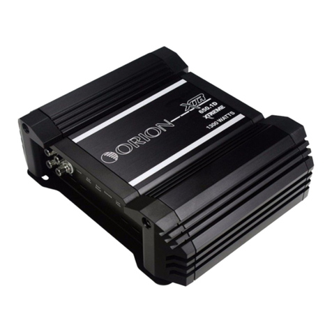
Orion
Orion HCCA 225G4 User manual

Orion
Orion XTR1500.1D User manual
Orion
Orion Hott T 600 User manual