Orion StarShoot G Series User manual

#51452
#51883
Orion®StarShoot™
G Series CMOS Cameras
IN 628 Rev. E 01/21
INSTRUCTION MANUAL
#51452 G10 Color
#51454 G10 EU/UK
#51457 G16 Mono
#51458 G26 APS-C Color
#54290 G21 Color
#51883 Mini 6.3 Color
#51884 Mini 6.3 Mono
#51860 G24 Full Format
#51862 G10 Mono
#51863 G26 APS-C Mono
Mini 6.3 Color #51883
Mini 6.3 Mono #51884
#51458 G26 APS-C
Corporate Offices: 89 Hangar Way, Watsonville CA 95076 - USA
Toll Free USA & Canada: (800) 447-1001
International: +1(831) 763-7000
Copyright © 2021 Orion Telescopes & Binoculars.All Rights Reserved. No part of this product instruction or any of its contents
may be reproduced, copied, modied or adapted, without the prior written consent of Orion Telescopes & Binoculars.
AN EMPLOYEE-OWNED COMPANY

The StarShoot CMOS Camera (G10 and larger)
The StarShoot Camera is a high resolution CMOS imager with
a dual-stage, regulated thermoelectric cooler to enable maxi-
mum imaging performance. It is very sensitive and capable of
detecting faint deep sky objects in a short exposure; and longer
exposures or higher gain settings can reveal extremely deep
elds with subtle nebulosity and galaxies in the background. The
unique versatility of CMOS chip lets you take advantage of the
densely-packed pixel array. 1x1 mode utilizes the full resolution
of the camera, providing the most detailed images and largest
possible prints. The one-shot-color versions offer the easiest
path to a full color image, with the Bayer matrix over the chip
to encode the color data without having to shoot through indi-
vidual lters. The Monochrome versions are the most sensitive
StarShoot cameras, because of that monochromatic nature
of the chip, but will need to shoot through different color lters
in order to produce a full color image. Binning in 2x2 mode or
higher shortens the exposures necessary and full well capac-
ity of each pixel at the expense of resolution. Binning in 2x2
mode can be especially useful for longer focal length and higher
focal ratio telescopes, as well offers super-fast downloads when
focusing with a Bahtinov mask or V-curve assisted motorized
focuser.
Feature Highlights
• Simple interface: A USB 3.0 port and power port are all that
are needed to power and connect to the Camera (Figure 1).
• Dual-stage thermoelectric cooler: Dramatically reduces
thermal noise in all images, down to approximately 35 degrees
C from ambient temperature.
• Regulated cooling: Enables you to set the exact tempera-
ture within the cooling range of the camera. This allows you to
take calibration images like dark frames at the exact same tem-
perature as your light frames, making for the cleanest images
possible. Additionally, since you can match the CMOS tempera-
ture at any time (within the range of the cooler), you have the
freedom to take dark frames when it’s most convenient for you,
so you don’t have to use up valuable imaging time to take dark
frames.
• High speed USB 3.0 interface and internal memory buf-
fer: The 512 megabyte on-board memory buffer ensures a
Welcome to the exciting world of astro-imaging. Your new StarShoot™ CMOS Imaging Camera is capable of capturing profes-
sional quality astro-images of your favorite celestial objects.You can showcase spectacular images on your computer, share them
on the internet, or print them. The camera’s large pixel array provides very high resolution images which are great for publishing in
large prints. Please read this instruction manual before attempting to use the camera or install the needed software. This manual
covers installation of your camera along with basic functions of acquiring images using the included software. To get the most out of
your camera using 3rd party dedicated astronomy apps coupled with the universal ASCOM driver for the G Series Camera, please
consult the software help les and manuals included with the individual software packages available on the market. Some of our
favorite programs are mentioned below. Note: This manual covers the StarShoot Mini cameras as well as the larger format cooled
G series cameras. Some features will only be available on specic models.
Figure 1. The back panel, with USB ports and LED indicator lights of
the G10
Figure 2a. All of the included parts of the Starshoot G10 and
above. Note: AC cable will differ in EU and UK .
2
Case
Camera
2"
Nozzle
USB 3.0 cable
AC Adapter

clean image download each time, even if the system resources
of your PC are temporarily compromised.
• Two port USB 2.0 hub (Figure 1):means cable manage-
ment is much easier. Plug up to two other USB devices (such
as an autoguider and electronic lter wheel into the camera, and
only have the USB 3.0 cable and power cable coming off the
telescope.
• Status indicator lights (Figure 1):Shows connection to the
camera, data transfers (ashing light), power to the electronics,
TEC (thermoelectric cooler) and fan.
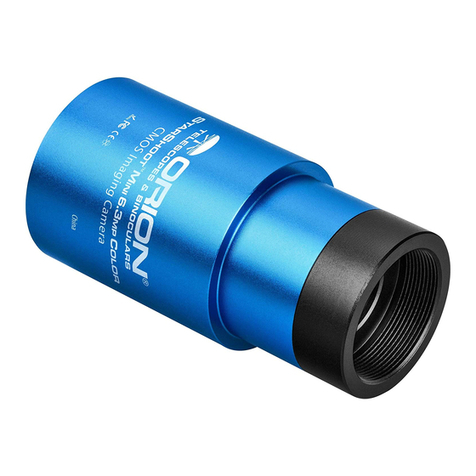
The StarShoot Mini CMOS camera
The StarShoot Mini cameras (6.3mp Color and Monochrome)
are lower cost alternatives to the larger G10 and above cam-
eras. They are not cooled which means that while the inher-
ent noise will be a bit higher, the size, cost, and power require-
ments are considerably reduced. The StarShoot Mini cameras
are based around the Sony IMX 178 CMOS chip, and excel at
planetary imaging because of the super-fast frame rates and
the tiny 2.4 micron pixels. In addition, they are capable of deep-
sky imaging with exposures up to 1000 seconds. They also fea-
ture a standard SBIG autoguider port, so they can be used as
a very sensitive autoguider while imaging through a different
camera. For the most sensitive guiding, the mono version is
recommended. All subsequent sections of this manual (includ-
ing the deep-sky imaging section) pertain to the StarShoot Mini
cameras as well, but some features such as the TEC cooler and
AC power requirements, do not apply. The Mini cameras are
powered fully by the USB 3.0 port on your computer.
2. Getting Started
Parts List
• StarShoot G Series camera
• 1.25” nosepiece (Mini), 2” nosepiece (G10 and above)
• USB 3.0 cable
• SBIG guide cable (Mini only)
• DC power adapter and cable (G10 and above, and different
AC plugs provided in EU/UK versions)
• Hard carrying case (G10 and above)
• Various adapter/spacers (G24 only)
Telescope
The StarShoot can be used with most telescopes on the mar-
ket.The Mini cams slip into a 1.25” focuser, and the larger format
cameras into a 2” focuser (Figure 3a). The cameras are also
compatible with any focuser that includes male 42mm T-threads
(G10 and above) or male c-mount threads (StarShoot Mini).
Caution: Be sure to always rmly tighten the thumbscrew(s)
that secure the camera in the telescope focuser, or it could
fall out and onto the ground! If your telescope has T or C
threads for direct camera attachment, a more secure connec-
tion can be made. First, unthread the 1.25” or 2” nosepiece from
the camera body to expose the C or T threads on the camera
front housing. Then simply thread the camera onto your tele-
scope (Figure 3b).
Back-focus Requirement (G10 and above)
The camera requires 17.5mm (0.689") of back-focus. This is the
distance from the front threads to the CMOS sensor.This is nec-
essary info to have when calculating spacers to put behind a
Coma Corrector or Field Flattener, which usually require 55mm
of space for optimum performance. Because of the necessity
of a coma corrector or eld attener with the G24 Full Format
on many style telescopes, the G24 includes some adapter and
spacer rings to reach the optimal 55mm spacing. Other adapt-
ers in various sizes might be required depending on your spe-
cic attachments. Step down adapters from 54mm, 48mm, or
42mm with 0.75mm thread pitch are widely available from many
online retailers.We have found Blue Fireball brand adapter rings
come in a wide selection of sizes, and might be of help to t your
specic need(s).
Mount
Deep sky imaging with the G Series usually requires an equato-
rial mount with a right ascension (R.A.) motor drive. The goal
for your mount is to seamlessly track the apparent movement
of the sky as the Earth rotates. The tracking must be very accu-
rate, or the object you want to image will drift and blur across
the camera’s eld of view while the exposure is taken. Even a
small amount of drift will cause a star to look oblong instead
of round. We recommend using a high-quality equatorial mount
which utilizes periodic error correction (PEC) or has the ability
to interface with an autoguider.
Figure 2b. The included parts of the StarShoot Mini.
Figure 3a. The Camera, installed
in a 2"focuser using the included
2" nozzle
Figure 3b. T-threads for
direct threaded connection (G10
and above). StarShoot Mini
cameras slip into 1.25” focuser,
or use c-mount threads. G24
has larger 54mm opening and
includes step down rings
3

Computer
The camera requires a Windows PC to operate the camera. For
astro-imaging in the eld at night, a laptop computer is highly
recommended. The included software requires Windows 7, 8,
10, and for full data speed, a USB 3.0 port is required. A large
hard drive is also recommended, as the individual image les
are quite large, and can take up a lot of disk space.
Power (G10 and above only)
The camera requires 12 volts DC (12VDC) to run the TE cooler.
Power to the cooler and fan is supplied by the included 3amp
AC/DC transformer when plugged into an AC outlet. Imaging in
the eld away from AC power usually requires the use of a por-
table eld battery to supply power. Make sure the power supply
provides at least 3 amps of current for the duration of your imag-
ing session. This allows the camera's TEC to use 100% of its
potential cooling power. The 12v input port accepts a standard
5.5mm/2.1mm DC TIP POSITIVE plug.
Software and Driver Installation
The software and driver must rst be downloaded from the Orion
website before plugging in the camera. Please go to: www.tele-
scope.com/Gseries to download all the relevant software for
your camera. Downloadable les include:
• StarShoot Image Capture: camera control program
• G series direct driver: for DirectShow applications
• G series ASCOM driver: for camera control in 3rd part
astro-imaging software.
Note it is HIGHLY recommended to install the ASCOM platform
and download the G series ASCOM driver to use with the cam-
era. Dedicated 3rd party camera control programs are available
online which will unlock the full astro-imaging potential of the
camera. To install the ASCOM platform, visit www.ascom-stan-
dards.org and click the download button. Don’t forget to also
install the G series ASCOM driver from Orion’s website AFTER
you install the main ASCOM platform. When connecting to the
camera in a 3rd party program using ASCOM, choose “ASCOM
camera” from the camera selection menu, and then the G series
camera should appear in the ASCOM camera selection window
if the driver is properly installed.
1. Download all relevant les from the Camera download
page
2. Double-click on the install .exe for the Image Capture
program, the driver, and the ASCOM driver, and follow the
onscreen directions for installation. Do not plug the camera
in until the drivers have been installed for the camera.
3. Once the driver and software has been installed, plug the
camera into an available USB 3.0 port, and connect the
AC power cord to the DC input on the camera (Figure 1),
and connect to AC power (G10 and above only).
4. Windows will take a moment to recognize the USB device
plugged in, and once that is complete, you can open up
the StarShoot Image Capture program to connect to the
Camera.
Hardware setup
Now that the camera drivers and software are installed, it’s time
to connect the camera to the telescope, and open up the soft-
ware. Install the camera into your focuser, and for the G10 and
above: connect any peripheral devices to the two USB 2.0 ports
on the camera, and connect the camera to power. Please note
the AC/DC transformer has a relatively short DC cable length.
This prevents 12v voltage from dropping over longer runs, but
you may nd it difficult to reach an AC outlet depending on your
scope setup. Use of an extension cord on the AC side of the
adapter is suggested, and the DC transformer itself can rest on
the tripod accessory tray, or secured with Velcro or some other
method directly to the tube wall or telescope rings. If you need
to extend the 12v side of the power cable, a 5.5mm/2.1mm DC
extension cable (available from your local electronic supply) can
be used, but please try to keep the length of the cable as short
as possible. Finally, for all cameras including the Mini, connect
the USB 3.0 cable from the camera to an available USB 3.0 port
on the computer.
Focusing the camera for the rst time can be tricky, since the
camera may focus at a completely different place from where
an eyepiece focuses. It is recommended that you rst center a
bright star in a 25mm eyepiece before attaching the camera, to
be sure the camera is centered on the star. Even very far out
of focus, you should be able to see a fat disk (the out-of-focus
star), to determine which way to turn the focus knob to bring the
star down to a focused point.
4. Software
The next section with document connecting to the camera and
basic image downloads. The included software will run the basic
astro-imaging steps including image download, cooler control,
exposure controls and such, but please note that this software
only touches on the basic functions of acquiring astro images.
To get the best results with more advanced processes such
as stacking multiple long exposures together to reduce noise,
manual dark frame subtractions, at eld and dark frame stack-
ing for smoother calibration frames, and other processes, it is
HIGHLY recommended to control the camera with an ASCOM
compatible capture program. Some are free on the web, others
are paid, but there is a vast array of programs available that will
be compatible with the camera. Here are some of our favorites:
DeepSkyStacker: http://deepskystacker.free.fr/ - Excellent free
program for pre-processing that simplies the alignment and
stacking of your images. Automatically monitors a directory
where images are saved, and processes on the y. Add all the
calibration frames, including darks, ats, biases, and step back
while the software does the rest giving you output ready for post
processing in programs such as PhotoShop.
RegiStax: www.astronomie.be/registax/ - Excellent free pro-
gram for aligning, stacking and processing of AVI video les,
ideal for capturing lunar and planetary video, splitting the video
into individual frames, analyzing each frame and aligning/stack-
ing/processing the best ones for pulling out ne details.
SharpCap: sharpcap.co.uk – Free camera control and capture
program. Features include video and long exposure control, at
4
Figure 4. Primary software screen.
Figure 4a. Camera model – click this text to connect to the
camera and start the preview.
eld and dark frame subtractions, histogram control, excellent
focus assist routines including Bahtinov mask overlays and
FWHM measurements, and MUCH more!
Sequence Generator Pro: mainsequencesoftware.com – free
45 day trial. Excellent Image Capture suite to control all aspects
of your setup. Create sequences of exposures of different
lengths, control a Go-To mount for automatic pointing and auto-
centering in any part of the image, auto v-curve focusing with
a compatible electronic focuser (without having to re-center to
a target star), autoguider control, and a host of other features.
Nebulosity: stark-labs.com – free demo available to try.
Powerful, yet very easy to use image capture and process-
ing program. Excellent processing routines such as aligning/
stacking and dark/at/bias handling. An excellent choice for the
beginning astro-photogra-
pher getting into processing,
yet will carry over for more
advanced users as well.
Orion StarShoot
Image Capture
Plug the camera into the
USB 3 port, and into AC
power. When you open
Orion Starshoot Image
Capture, you’ll be presented
with the main preview win-
dow on the right, and the
control options on the left-
hand side. (Figure 4). On
the top of the left-hand side,
click the camera name to
start a video preview (Figure
4a). Scrolling down the left-
hand side, you’ll nd all the
controls for operating the
camera. The primary window
to control the exposure and
to use rst is the Capture and
Resolution window (Figure
5). In this window, you can
set either video or still image mode (trigger mode), as well as
set the resolution and gain of the camera and set single, loop-
Figure 5.The Capture and
Resolution window pane
5

6
ing, or sequence shots to be saved automatically in a chosen
directory.
Scrolling down further along the left side, you’ll nd windows
for other camera attributes including bit depth (always choose
the highest bit depth to get the most detail and quality out of
the image), binning control (1x1 is full camera resolution),
histogram, and cooler control. There are other windows pres-
ent, but the ones listed above are the most important ones
when taking your rst image. Some windows are not appli-
cable to astro-imaging, and can be shut off by going into the
Options>preferences menu.
To take your rst image, focus must be achieved. With a CMOS
camera, one of the quickest and easiest ways to focus is to
point the camera at a bright star, and choose a fast video frame
rate with higher gain settings so you can watch the star in real
time, and focus until the star becomes a point.
Focusing
1. Make sure the camera is in preview mode – if not, click the
camera name in the top left window, to turn on streaming
preview mode.
2. In the Capture and Resolution window (Figure 5), set
the resolution to full, the gain to somewhere in the
middle of the slider, and the exposure to video mode
with “auto exposure” unchecked, and an exposure time
to somewhere around 200-500 milliseconds. This should
provide you with several frames per second, enough to
see a real time focus preview.
3. This should be good enough to see a bright star like
Vega, provided it’s in the eld of view, and relatively close
to focus. If you see nothing, but are sure the star is in the
center of the eld, adjust your focus in and out because
a very out of focus star will spread out and become quite
dim.
4. Once you acquire the star, center it, and focus until it
looks like a tiny point. At this point you are probably over
exposing the star, and can back off on the exposure
time and gain settings. If the star is in the middle of the
eld, you can also reduce the resolution setting on the
chip, in order to speed up the frame rate, to get a super
responsive live focus. Readjust focus until the star is as
tiny as possible. At this point, everything including the
moon and a distant galaxy will be in focus.
5. If you wish to ne tune the focus further, a Bahtinov mask
is an ideal method of focusing with Orion StarShoot
Capture, as it is quite an accurate method using medium
brightness stars. Contact Orion or search for Bahtinov
mask on www.telescope.com for more details, and to
purchase a Bahtinov mask for your specic telescope.
Your First Lunar/Planetary Image
The moon is perhaps the easiest object to get your rst image,
as it is very bright, and easy to nd. Planets are also easier than
nebulae to capture, since you’ll be streaming a video le, and
can use programs such as Registax to process the video le.
1. Go to the Options menu, click preferences, and under
the Record heading, choose a directory location for your
saved les, naming convention of your choice, and make
sure the le type is set to AVI.
2. In the Capture and Resolution window pane, check Video
Mode, uncheck auto exposure, and use the Exposure
Time slider to nd an exposure that looks good. Planets
do well with lots of short exposures, so if the exposure
time is too long, experiment with raising the gain, and
lowering the exposure value. It will be more noisy, but the
frame rate will be higher, and the exposure time will be
lower.
3. When ready to record, press the record button and press
it again when your video is the desired length. In the
Options menu, under Record preferences, you can set
limits to time of the video, as well as number of frames.
4. You can then load your AVI le into a 3rd party program
such as RegiStax, in order to process the lunar or
planetary details present in the video le.
Auto Exposure can be used if desired, but manually adjusting
the exposure values provides the best control over the image.
Check the “Auto Exposure box, and drag the box over an area
you wish the system to measure.You can resize the box accord-
ingly. Then set the Exposure Target, and the system will try to
keep the exposure close to that target exposure value by adjust-
ing the exposure time automatically.
Your First Deep Sky Image
1. Now that you’re focused, slew to an object you wish to
take a picture of, and the exposure and gain settings will
Figure 6b. Histogram window showing the screenstretch
adjustment bars
Figure 6a. Live histogram with “humps” in the normal range
(left of center) for a target deep sky exposure

Figure 7a. 120 second “raw” image of the Veil with no histogram
stretch. Note the faint details that are barely visible. 7b. After
adjusting the Range bars to just wider than the histogram hump,
more detail appears.
need to be adjusted for best the best possible result. For
longer nebulae exposures, trigger mode is recommended.
2. For a nebula or star cluster, choose something bright
for your rst target, and ideally an autoguider is already
locked on and tracking a star, so your resulting images are
well guided. Pick an object like the Ring Nebula (M57),
Dumbbell (M27), or Orion Nebula (M42) since they are all
very bright and easy to see in short exposures to make
sure the framing is correct. Center the object and proceed
to set the exposure.
3. Set the analog gain slider to around 25% from the left
(around 40), and a trigger mode exposure of 30 seconds,
and make sure the bit depth is set to the highest bit depth
possible. This is just a starting point, these numbers may
have to be adjusted depending on your resulting image.
4. Click Single and wait for the image to download. You
should see a rather grainy looking image of your target in
the preview window on the right. Now is the time to look
at the histogram window, and determine what needs to
change in order to get the best exposure. Scroll down the
left side panel to nd the histogram window.
5. The histogram shows a graphical representation of the
number and brightness of the pixels in the image. The far
left of the histogram is black, or no light on a given pixel,
and the far right is full white, or fully maxed brightness for
those pixels. A normal astrophoto has a lot of black in it, so
the histogram bump should be left of center (approximately
near the left 1/4 to 1/3 of the histogram for the hump) for
a properly exposed photo of a nebulae with a lot of black
sky around it (Figure 6a). If the hump is too far to the right,
either the exposure or the gain is set too high, and you’re
recording too much background light pollution.
6. Adjust the exposure to somewhere between 30 seconds
and 180 seconds. For a CMOS chip like the G Series,
individual exposures probably do not need to be longer
than 180 seconds, especially when you’ll be stacking
many shots together for the best results. The G16 color
and G21 color camera are not quite as sensitive as the
G10 color, so exposures longer than 180 seconds may
be possible and advantageous to gather more light.
The G16 mono is the most sensitive of all -- but since
it is a monochromatic camera, in order to obtain a full
color image you’ll need to shoot through red, green, and
blue lters, and process the resulting frames together to
produce a color image. If the histogram still doesn’t fall into
the proper area, the gain can also be adjusted. Higher gain
setting means more noise in the image, but it will provide
more sensitivity for a given exposure. Finding the right
exposure vs. gain combination is a matter of trial and error,
and will vary depending on the telescope focal ratio and
sky conditions.
7. If you want to “screen stretch” the histogram, meaning
change the black and white points in the image in order to
see what kind of faint detail you have captured, grab the
left and right edges of the histogram window, and slide the
vertical bars closer to the histogram bump. Moving the
right edge bar closer to the end of the hump will raise the
brightness of the entire image, and moving the left edge
bar closer to the start of the hump will darken down the
black point, boosting the contrast. (Figure 6b). Note that
the live histogram stretching will NOT change a trigger
image that is displayed on the right. It will affect the NEXT
image that downloads from the camera, so take another
exposure and check the results.
8. Once you’ve dialed in the right histogram, it’s time to start
a sequence so you can stack several images together.
Remember that each individual image will have lots of
noise, and only by stacking many images together will you
get a smooth low noise image.
9. In the Capture and Resolution window, click “Options”
in the lower right corner of the window and choose a
le location to save your resulting images. Make sure to
save them as .t les so 3rd party astro-imaging software
can read them (.t is a standard in the astro-imaging
community). Verify that the resolution you wish to image
at is set, and also make sure RAW is set for the le type.
RAW ts les are saved before color converting so other
programs can read the raw les and provide the best data
from the camera. Also, make sure “Light Frame” is selected
in the window across the top, so the correct meta-data is
7
7a
7b
7b. After adjusting the Range bars to just wider than the histogram
hump, more detail appears.
Figure 7a. 120 second “raw” image of the Veil with no histogram
stretch. Note the faint details that are barely visible.

Figure 8. Veil after pre-processing in DeepSkyStacker (dark frames,
flats, and stacking) and post-processing in Photoshop (levels, curves,
and more).
8
saved in the .t le header. Many programs look to the ts
header to determine the type of le (Light, Dark, Flat...), so
they can be automatically processed correctly without the
user specifying the type of image.
10. Once everything is set and your autoguider is up and
running locked on and tracking a star, choose a number
of shots in the sequence, then click sequence and sit
back and let the camera collect the images. Later, when
processing, if you nd your stacked images too noisy, you’ll
want to stack a larger number of shots together to reduce
the noise.
11. When those exposures are nished, you might also want
to collect some dark frames, so you can subtract them
from the light frames in your 3rd party astro-imaging
software. Choose “dark frame” instead of “light frame”,
and take at least one dark frame with the cap on the
telescope that you will later subtract from the light frames
in your other software. Darks should be taken at the same
exposure, temperature, and gain setting as the lights
you previously took. See below for more discussion on
calibration frames such as darks and ats.
Congratulations, you’ve just taken your rst series of deep-sky
images with your new camera! It’s now time to do some pro-
cessing in some of those other suggested programs such as
DeepSkyStacker or Nebulosity in order to get the cleanest nal
image possible. It’s not uncommon to shoot dozens of light
images, especially when imaging something faint that hides in
the background noise. The greater the number of images, the
more you can push the processing and pull out the detail. Even
dark frames can benet from averaging many together. A mas-
ter dark or at made of many individual frames has signicantly
less noise than only one.
Also, make sure to adjust the histogram to show some of the
faint detail that may not be visible upon rst downloading an
image. Previously, the “Live Histogram” adjustment was shown,
but there’s another way to adjust the histogram of a saved
image. Figure 7a and 7b show a downloaded 120 second
image of the Veil Nebula. Figure 7a shows the full range (select
Menu>Process>Range to bring up a histogram of that image).
Notice how faint the nebulae looks? That’s not uncommon for
a nebula to look like this right out of the camera, as it is just
barely brighter than the background light pollution. Figure 7b is
a Range adjusted shot, to show fainter detail. Notice how the left
and right range lines are set just outside each end of the histo-
gram? The background is brighter, but ready for more process-
ing in Photoshop to reset the black point and clean the image
up. Figure 8 is a nished image, with dark frames subtracted
and a stack of thirty 120 second light frames, 9 dark frames,
processed in DeepSkyStacker and Photoshop.
Imaging with a Mono camera
One shot color cameras are relatively easy to get a nal image
from because there is less processing involved. But color chip
cameras suffer from less sensitivity to light than a monochrome
camera does. The reason is due to the Bayer Matrix over the
chip. The pixels are arranged in squares of alternating colors
(for example RGGB in the G10). This means that for every four
pixels in a square, only one of them is sensitive to red light, and
only one to blue. But in a monochrome chip, every pixel sees
ALL of the photons of light across the visible spectrum. The
result is a much more sensitive chip. This is much more versa-
tile, because you can put any kind of lter in front of the camera,
depending on the wavelength of light you want to capture. And
not just Red, Green and Blue -- consider narrow-band imag-
ing with Hydrogen-Alpha, Oxygen-III, and Suphur II lters as
your RGB channels. This can dramatically boost the contrast
on nebulae, and also allow imaging even in more severe light
pollution than otherwise would be possible. Also consider a
motorized lter wheel such as the Orion StarShoot 2” Motorized
USB Filter Wheel to automate the process of switching lters
between exposures.
5. Cooling – for less noise!
The TEC in your G10 and above is designed to reach tempera-
tures of up to 35 degrees below the ambient temperature. As
the chip gets colder, noise becomes less pronounced, so the
9b. Cooler control window. Set a specific temperature that is
somewhere less than 35 degrees below the ambient temp
Figure 9a. Current temperature of chip. Shown in the very bottom
right corner of the software screen.

9
resulting image is cleaner. In StarShoot Image Capture, you
can nd the current temperature of the chip in the lower right-
hand corner of the screen, next to the current resolution (Figure
9a). Cooler control is located down the list in the left hand win-
dowpane (Figure 9b). Note the current temperature of the cam-
era, then turn the cooler on, set a target temperature, and wait
for the chip to reach that target temp. Please note that the colder
the chip, the more prone to internal dew. The CMOS chamber
has been purged of moisture at the factory, but pushing the
cooler to its limit may still cause whatever moisture remains to
condense on the chip.You’ll notice this in the image as a circular
pattern that grows in the image, and a major loss of detail.
If the chip dews over, raise the target temperature and give the
chip a few minutes to acclimatize. Raising the temp to 0 degrees
C should remove any dew after a few minutes. It’s good to reduce
the temperature of the chip, but it doesn’t have to be all the way
down to 35 degrees below ambient. Somewhere between 15-25
degrees below ambient still provides a great noise reduction,
but with much less chance of the chip dewing over. Once the
target temp is reached and is stable, proceed with taking your
light and dark frames. They must both be at the same expo-
sure length and temperature for the darks to correctly calibrate.
Since the cooler is regulated, you can also use these darks in
subsequent imaging sessions, as long as you keep the target
temperature the same night to night for your light frames. This is
another good reason not to reduce the temperature to its lowest
possible setting. If the next night is warmer, it won’t be possible
to drop the cooler as far from ambient temperature.
Conversion Gain
Along the left hand pane is a window for conversion gain, and
options (if your specic camera supports both options) for LCG
and HCG -- low and high gain. LCG should be used most of
the time, especially when a lower gain setting is used. However,
if you are boosting the gain up high to keep exposures times
lower, try switching to HCG and readjusting gain, which can
reduce read noise in the chip without losing as much dynamic
range in the image. But when in doubt, stay in LCG mode, and
your images will turn out ne. The ASCOM driver also includes
LCG/HCG settings when in 3rd party control programs.
Dark Frames
Dark frames are images taken with no light coming into the
camera. A dark frame is typically taken with the telescope cap
attached. The only data in the image is the inherent camera
noise. The noise contains the dark current (background noise
level), read noise (noise introduced during camera readout and
download) hot pixels (bright dots in the image) and amp glow
(Figure 10). All of this noise exists in your raw astro-image too,
which distracts from the detail you want to see. To eliminate
most of the camera noise, you can take several dark frames,
average them together, then subtract this “master dark” from
your “light” astro-images. Note: Make sure the cooler set point
and camera temperature are the same as they were when
you took your light frames. Dark frames are handled through
most of the 3rd party control programs listed previously.
Flat Field Frames
Flat Frames are more advanced, and mentioned here as a point
of reference. A at eld is an image taken with uniform feature-
less light entering the telescope, such as a blue sky in the early
morning or after sunset. Flat elds solve a number of issues in
your astroimages:
Vignetting
Vignetting in a telescope reveals edge-darkening in the astro-
image. Vignetting is more apparent when the telescope’s illumi-
nated eld is not large enough to illuminate the full area of the
chip. As a result, more light is detected in the center of the image
compared to the edge.
Dust and Particles
Dust and particles will inevitably show up in your raw astro-
images. Large particles on the camera optical window some-
times look like unfocused circles or doughnuts in your images.
It’s too late to clean your camera if you are already imaging in
the eld at night. And even when the camera is clean, dust usu-
ally nds a way to show up in your images.
Telescope Artifacts
Very large particles or other artifacts in your telescope can affect
your astro-images. Insufficient telescope baffling or poor colli-
mation can also cause unsymmetrical eld illumination in your
images.
To take a flat field image:
1. Ensure that the telescope is focused and ready for astro-
imaging.
2. Point the telescope at a uniform and featureless light
source, like the sky at dusk or dawn, or a blank white
sheet of paper. Make sure the camera orientation
is exactly the same as it is or was for astro-imaging
Figure 10. A 120 second dark frame, from a G10. Note the amp
glow on the upper right side, this is standard for the ICX294 chip, and
is removed from light images during dark frame subtraction. The G16
will show a different dark frame amp glow signature, and the G26/
G24 have ZERO amp glow!

(Although the telescope is pointing at a featureless
surface, the focus and orientation must be set as it
normally would be for astro-images.)
3. Set the Frame Type in your imaging control program to Flat
Field for correct meta data agging in the ts header.
4. Set the exposure to result in a histogram which has a
hump at around 1/3 to 1/2 of full exposure.
Import your Darks and Flats into the programs mentioned above
for full image calibration of your astro-photos.
Image Processing
It’s not uncommon to use 3-4 programs to tweak the astro-imag-
es you’ve taken to get the best possible nal result. Please delve
into the manuals for the other programs listed above, along with
output for Photoshop, Lightroom, or other standard image pro-
cessing programs. The images taken for this manual and on
telescope.com were all taken using a combination of StarShoot
Image Capture, SharpCap, DeepSkyStacker, and PhotoShop.
Color Conversion (one shot color cameras only)
It was mentioned previously to save the images in the RAW
.t format, for later processing in 3rd party software. RAW is a
“black and white” format with a “screen door effect” laid over the
image. This screen door is the Bayer Matrix, and contains the
color data. When you convert the RAW format to a color for-
mat, the screen effect disappears and you’re left with a full color
image. The preview window in StarShoot Image Capture shows
a color image, but if you set the saved le type to RAW, you will
save an unconverted black and white image in the .t format.
To convert to color, see the instructions included with the 3rd
party software packages, but you’ll have to also determine the X
and Y offset, in order to reproduce correct colors. This is differ-
ent in each software program and usually requires experiment-
ing in order to correctly convert. Color balance may also have
to be adjusted to correctly display the image from a chip that is
most sensitive in Green, and less sensitive in blue. For exam-
ple, in DeepSkyStacker, we found the best setting was “generic
RGGB” for the Bayer matrix lter, and “Bi-linear Interpolation”.
After that, color balance could be used to rebalance the back-
ground levels to a neutral color.
NOTE: the G16 Color Bayer Matrix is arranged GRBG or
BGGR (depending on the software you are using), instead
of RGGB in the others. X and Y offsets are different.
ASCOM Driver
The ASCOM driver allows the camera to be used with any of
the programs listed above, along with any others that support
ASCOM cameras. Please download the ASCOM platform
from ascom-standards.org and make sure to install the camera
ASCOM driver from Orion’s website. When in 3rd party camera
control programs, the camera gain settings can be controlled in
the ASCOM setting window for the camera. Open the ASCOM
camera settings, adjust the gain, and experiment with expo-
sures as detailed above. Since stacking reduces noise, it can
be benecial to have a bit more noise in the image, if it helps
keep the exposure times down. One last thing to note, some
programs may use a percentage for gain, others may use the
actual gain numbers. If the gain range is 0-100, it’s using a per-
centage of total gain.
G24 Spacing rings
Since the G24 is a full format camera chip, it becomes neces-
sary to use a coma corrector on most Newtonian reectors, or a
eld attener on refractors in order to optimize the distortion cor-
rection of the telescopes eld. Most coma correctors and eld
atteners need to be positioned with 55mm distance between
the chip and the attachment threads on the lens. This 55mm
distance is the default spacing for a DSLR housing, but cameras
such as the G24 have a chip mounted closer to the front open-
ing (17.5mm in the case of the G24). Because of this, we are
providing several spacer adapters that will replace the standard
2” nozzle on your G24 (gure 11). Thread in the 54mm – 48mm
ring rst (21mm length), then the 16.5mm extension ring, and
then your coma corrector/eld attener (assuming it has 48mm
t-threads. This will provide 55mm distance between the chip
and the corrector/attener.
If you have a coma corrector or flattener that uses 42mm
threads, use the 48mm to 42mm zero prole ring to step the
threads down to 42mm. We do not usually recommend this, as
a 42mm opening will vignette the larger chip, and the edges of
your eld will become darker.
Please note that the standard 2” nozzle that is included with the
G24 is threaded for Orion lters (M48 x 0.6mm), and does not
use the camera t-thread pitch of 0.75mm. If you wish to add the
extensions or purchase other length extensions online, make
sure to be using the native opening of the camera (M54 x 0.75),
or one of the spacing rings which also provides 0.75mm thread
pitch in either the 48mm or 42mm diameter.
Figure 11 The spacer rings included with the G24.
10
16.5mm extension ring
(48mm x 0.75mm)
54mm - 48mm reduction adapter (2"
OD, 21mm length)
48mm to 42mm
stepdown adapter
(zero profile),
0.75mm thread
pitch

11
Specifications
G10 Color G16 Mono
Sensor: Sony IMX 294 color CMOS, 4/3 format Panasonic MN34230 CMOS, 4/3 format
Resolution: Up to 4128x2808 Up to 4640x3506
Pixel Size: 4.63 microns 3.8 microns
Diagonal size of chip: 23.1mm 22.1mm
Bayer Matrix pattern: RGGB arrangement BGGR/GRGB (depending on software)
Exposure range: 0.1ms – 1000s 0.15ms – 3600s
Shutter: Rolling Shutter Rolling Shutter
Partial frame download: Region of interest and Sub-frame Region of interest and Sub-frame
download supported download supported
Binning: 1x1, 2x2, 3x3, 4x4 hardware and 1x1, 2x2, 3x3, hardware and software binning
software binning
ADC: 14 bit 12 bit
QE peak: 76% 60%
Read Noise: 1.12e@HCG Mode 1.2e@HCG Mode
Full Well: 66.6ke 20ke
Image Buffer: 512MB memory buffer 512MB memory buffer
Interface: USB3.0/USB 2.0 USB3.0/USB 2.0
Front nozzle threads: 42mm T-threads 42mm T-threads
CMOS chip window: IR blocking, 380-690nm IR blocking, 380-690nm spectral range bandpass
(Color). AR coated window, non IR blocking (Mono)
Dimensions: 80mm x 103mm 80mm x 103mm
Weight: 535g 535g
Back Focus: 17.5mm 17.5mm
Cooling: Regulated Two Stage TEC, Regulated Two Stage TEC,
~35 deg C from ambient ~40 deg C from ambient
Camera electronic power: DC 5v from PC USB port DC 5v from PC USB port
Cooler power: 12v/3a 12v/3a
G21 G26 Color
Sensor: Sony IMX 269 CMOS, 4/3 format Sony IMX571 CMOS, APS-C format
Resolution: Up to 5280x3956 Up to 6224 x 4168
Pixel Size: 3.3 microns 3.76 microns
Diagonal Size of chip: 21.8mm 28.3mm
Bayer Matrix patter: RGGB RGGB
Exposure Range: 0.1ms - 3600s 0.1ms - 3600s
Shutter: Rolling Shutter Rolling Shutter
Partial frame download: Region of interest and Sub-frame Region of interest and Sub-frame download
download supported supported
Binning: 1x1, 2x2, 3x3, 4x4 hardware and 1x1, 2x2, 3x3, hardware and software binning
software binning
ADC: 12 bit 16 bit
QE peak: 84% 80%
Read Noise: 1.62e@LCG Mode 1.16e@HCG Mode
Full Well: 23ke 51ke
Image Buffer: 512MB memory buffer 512MB memory buffer
Interface: USB3.0/USB 2.0 USB3.0/USB 2.0
Front Nozzle threads: 42mm T-threads 42mm T-threads
CMOS chip window: IR blocking 380-690nm spectral range bandpass IR blocking 380-690nm spectral range bandpass
Dimension: 80mm x 103mm 80mm x 103mm
Weight: 535g 556g
Back Focus: 17.5mm 17.5mm
Cooling: Regulated Two Stage TEC, ~40 deg C Regulated Two Stage TEC, ~35 deg C from ambient
from ambient
Camera electronic power: DC 5v from PC USB port DC 5v from PC USB port
Cooler power: 12v/3a 12v/3a

12
G24
Sensor: Sony IMX 410 color CMOS, full format
Resolution: Up to 6064 x 4040
Pixel Size: 5.94 microns
Diagonal Size of chip: 43.3mm
Bayer Matrix patter: RGGB
Exposure Range: 0.1ms - 3600s
Partial frame download: Region of interest and Sub-frame
download supported
Binning: 1x1, 2x2, 3x3, hardware and
software binning
ADC: 14 bit
QE peak: >80%
Read Noise: 4.48 – 1.95 e- (LCG)
0.68 – 0.3 e- (HCG)
Full Well: 104,000e- (20,000e- HCG)
Image Buffer: 512MB memory buffer
Interface: USB3.0/USB 2.0
Front threads: 54mm x 0.75mm thread pitch
CMOS chip window: IR blocking 380-690nm spectral range bandpass
Dimension: 89mm x 103mm
Weight: 718g
Back Focus: 17.5mm
Cooling: Regulated Two Stage TEC, Regulated Two Stage
TEC, ~35 deg C from ambient
Camera electronic power: DC 5v from PC USB port
Cooler power: 12v/3a
StarShoot Mini 6.3mp cameras
Sensor: IMX 178 (Color and Mono)
Resolution: Up to 3040 x 2048
Pixel Size: 2.4 microns
Diagonal Size of chip: 8.86 mm
Bayer Matrix Pattern: RGGB arrangement
Exposure Range: 0.244ms – 1000s
Partial frame download: Region of interest and Sub-frame download supported
Binning: 1x1, 2x2
ADC: 14 bit
QE peak: 78%
Read Noise: 1.4e – 2.2e (depending on gain setting)
Interface: USB3.0
Front Nosepiece threads: C-mount
CMOS chip window: IR blocking 380-690nm bandpass (Color version), AR coated, non IR blocking,
350-1050nm bandpass (Mono version).
Dimension: 72.4mm x 37mm
Weight: 61g
Camera power: DC 5v from PC USB port

13
G10 Mono
Sensor: Sony IMX 492 mono CMOS, 4/3 format
Resolution: 4128x2808 (best mode for deep-sky at 14-bit)
8184x5616 (unbinned 12-bit mode)
Pixel Size: 4.63 microns (default best mode for deep-sky)
2.3 micron (unbinned for lunar/planetary)
Diagonal Size of chip: 23.1mm
Exposure Range: .01ms – 1000s
Partial frame download: Region of interest and Sub-frame
download supported
Binning: 1x1, 2x2, 3x3, hardware and
software binning
ADC: 14 bit (at 4128x2808 resolution)
QE peak: >85%
Read Noise: 7.53 – 5.55 e- (LCG)
1.59 – 1.42 e- (HCG)
Full Well: 66,000 e-
Image Buffer: 512MB memory buffer
Interface: USB3.0/USB 2.0
Front threads: 42mm x 0.75mm thread pitch
CMOS chip window: AR coated window, non IR blocking
Dimension: 80mm x 103mm
Weight: 552g
Back Focus: 17.5mm
Cooling: Regulated Two Stage TEC, -40 deg C from ambient
Camera electronic power: DC 5v PC USB port
Cooler power: 12v/3a
G26 Mono
Sensor: Sony IMX 571 mono CMOS, APS-C format
Resolution: Up to 6224x4168
Pixel Size: 3.76 microns
Diagonal Size of chip: 28.3mm
Exposure Range: .01ms – 3600s
Partial frame download: Region of interest and Sub-frame
download supported
Binning: 1x1, 2x2, 3x3, hardware and
software binning
ADC: 16 bit
QE peak: >85%
Read Noise: 2.35 – 1.16 e- (LCG)
1.40 – 0.7 e- (HCG)
Full Well: 51,000 e-
Image Buffer: 512MB memory buffer
Interface: USB3.0/USB 2.0
Front threads: 42mm x 0.75mm thread pitch
CMOS chip window: AR coated window, non IR blocking
Dimension: 80mm x 103mm
Weight: 552g
Back Focus: 17.5mm
Cooling: Regulated Two Stage TEC, -40 deg C from ambient
Camera electronic power: DC 5v PC USB port
Cooler power: 12v/3a

14
Corporate Offices: 89 Hangar Way, Watsonville CA 95076 - USA
Toll Free USA & Canada: (800) 447-1001
International: +1(831) 763-7000
Copyright © 2021 Orion Telescopes & Binoculars.All Rights Reserved. No part of this product instruction or any of its contents
may be reproduced, copied, modied or adapted, without the prior written consent of Orion Telescopes & Binoculars.
AN EMPLOYEE-OWNED COMPANY
One-Year Limited Warranty
This Orion product is warranted against defects in materials or workmanship for a peri-
od of one year from the date of purchase. This warranty is for the benet of the original
retail purchaser only. During this warranty period Orion Telescopes & Binoculars will
repair or replace, at Orion’s option, any warranted instrument that proves to be defec-
tive, provided it is returned postage paid. Proof of purchase (such as a copy of the origi-
nal receipt) is required. This warranty is only valid in the country of purchase.
This warranty does not apply if, in Orion’s judgment, the instrument has been abused,
mishandled, or modied, nor does it apply to normal wear and tear. This warranty gives
you specic legal rights. It is not intended to remove or restrict your other legal rights
under applicable local consumer law; your state or national statutory consumer rights
governing the sale of consumer goods remain fully applicable.
For further warranty information, please visit www.OrionTelescopes.com/warranty.
This manual suits for next models
10
Table of contents
Other Orion Digital Camera manuals

Orion
Orion STARSHOOT G3 53082 User manual

Orion
Orion StarShoot G10 Color User manual

Orion
Orion StarShoot 52098 User manual

Orion
Orion 51883 User manual

Orion
Orion StarShoot AllSky Camera II User manual

Orion
Orion StarShoot AllSky II User manual

Orion
Orion StarShoot 52099 User manual

Orion
Orion 52084 User manual

Orion
Orion StarShoot AllSky User manual