Orion ODC-10000 User manual

• 2011.09.02
Address: 257-6, Gongdan-dong, Gumi-si, Gyeongsangbuk-do, Korea
Tel : +82-2-6678-8533, Fax: +82-2-6678-8599
ORION CO.,LTD.
www.oriondisplay.net
Thank you for purchasing our DVI Converter.
Please read through this user's manual for safety before installing this product.
This product is manufactured for Multi Plasma display model only.
User's Manual
DVI Converter
ODC-10000

DVI Converter ODC-10000
Innitely Expandable
ORION PDP CO., LTD. | 1
Product & Accessary
Please check remote controller and all the accessories are included in the box
Contents
1. Safety Precautions .....................................................................2
Cautions for DVI Converter ..........................................................2
Cautions for Electricity ...................................................................3
2. Names and functions ...............................................................4
Front side .........................................................................................4
Rear side ..........................................................................................5
3.
DVI-Converter Installation and configuration method
........6
3-1. Installation ...............................................................................6
4. How to configure DVI Converter control mode ............8
4-1. RS-232C Interface mode ..................................................8
4-2. Ethernet Interface mode .....................................................9
4-3. IP address Setting .............................................................11
5. How to use ................................................................................. 16
5-1. Using the main key of DVI converter ......................... 16
5-2. How to use OSD ............................................................. 20
5-3. How to use MSCS .......................................................... 26
6. DVI Converter Protocol ......................................................... 41
7. Check followings before asking for service ............... 60
8. Specification............................................................................... 61
DVI Converter (ODC-10000) : 1EA User's Manual : 1EA
DVI Converter_Bracket : 2EA
(Rack Mount Bracket)
PSW M3*8 : 6EA
DVI-D Cable
Power Cable
DVI Converter is a device to convert digital or analog signal into DVI image signal. 2 1.
independent DVI output ports can be used for the identical image output or for the
separate image output.
DVI Convert supports analog input of PC(RGB), COMPONENT(Y.Pb,Pr), and S-Video 2.
and digital input of DVI, HDMI, and HD-SDI. 2 LCD display windows show the input
modes and the DVI output resolutions, respectively. The input resolutions can be
selected from VGA(640x480) to UXGA(1600x1200), or DTV resolution from 480i 60Hz
to 1080P 60Hz
The information for the present input mode and output resolution is displayed on the 3.
LCD screen.
DVI Converter can be controlled through Rerial(RS-232C,) Ethernet or Front Key. 4.
According to user environment or preference, users can select the control method. If
Ethernet is selected, DVI Converter is controlled through LAN network. And, users can
control DVI Converter directly with Front Keys.
DVI Converter also can be controlled by a PC with the provided control program.5.
Product Introduction

DVI Converter ODC-10000
2 | ORION PDP CO., LTD.
Innitely Expandable
ORION PDP CO., LTD. | 3
Cautions for DVI Converter Cautions for Electricity
Safety Precautions1.
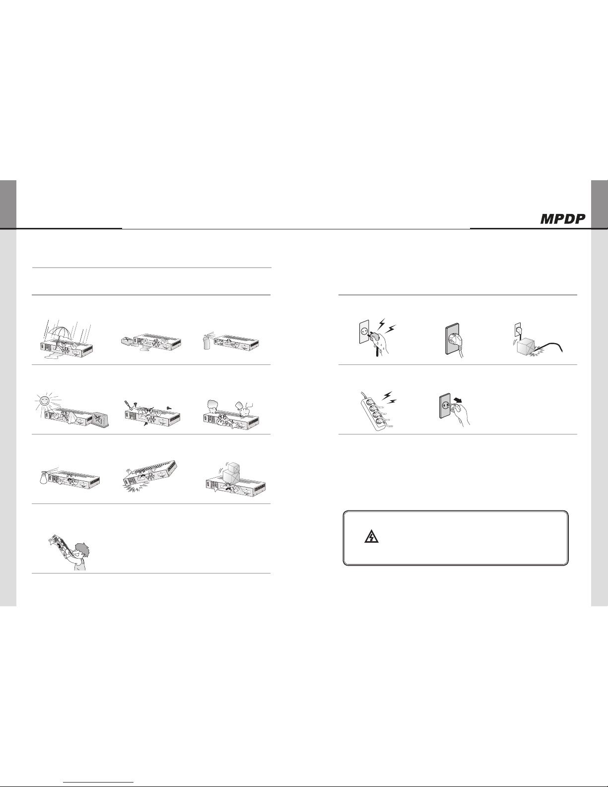
Please do not use at the places
of hot and humid environment.
- It may damage the product.
Please be careful not to soak
unknown material or liquid into
the product.
- It may damage the product.
Do not store or use flammables
like a combustible spray around
the product.
- It has a possible danger of explosion
or fire.
Do not put the product under
the direct sunlight or near to hot
places.
- It may cause fire.
Do not disassemble, repair or alter the
product with users' own intention.
- I t may cause an electric shock or fire. If you
need to test, adjust or repair the product,
contact with an authorized service center.
If you detect smoke, smell or strange sound
from the product, stop using the product
immediately, disconnect the power cable and
contact with an authorized service center.
- It may cause an electric shock or fire.
Do not spray water directly on
the product.
- It may cause an electric shock or fire.
Carefully move the product not to
give any shock.
- It may cause product malfunction.
Please do not stack heavy
objects on top of the product.
- It may damage
the product.
Please keep away from
children's reach.
- If they drop Remote Controller, it may
hurt the children or cause product
malfunction.
Do not touch the power cable
with wet hands.
- It may cause an electric shock.
Make sure the power plug is
properly connected.
- Loose connection may cause an
electric shock.
Do not put a heavy object on the
cable or fold the cable.
- It may cause an electric shock or fire.
Do not connect to a multi-
power-socket together with
many other electric products.
- It may cause an electric shock or fire.
Disconnect the power plug on
the occasion of lightning.
- It may damage the product.
Notice to users
Class A digital device
It is a device designed for business purpose with a safety
certificate for electromagnetic interference, which user should
be mindful of.
Warning

DVI Converter ODC-10000
4 | ORION PDP CO., LTD.
Innitely Expandable
ORION PDP CO., LTD. | 5
Rear side
INPUTA.
SDI: Y/Cb/Cr signal, BNC Connector
DVI-D: TMDS signal, DVI Connector
HDMI: TMDS signal, HDMI Connector
PC: Computer RGB analog signal, D-Sub 15Pin
COMPONENT: DVD signal, DTV-YPbPr signal,
BNC Connector
S-VIDEO: S-Video signal (Y/C), NTSC, PAL,
SECAM, 4Pin Mini Din
VIDEO: Composite signal, NTSC, PAL, SECAM,
BNC Connector
OUTPUTB.
DVI1: TMDS signal, DVI Connector
DVI2: TMDS signal, DVI Connector
RS-232CC.
IN: DVI Converter control, Daisy-chain input,
Firmware Update, 9Pin D-Sub
OUT: Daisy-chain output
ETHERNET PORTD.
IEEE Standard UTP Cable, RJ45 Connector
AC INPUTE.
AC 100~240V 50/60Hz
Front side
Names and functions2.
Input SourceA.
DVI, HDMI, SDI, PC, COMPONENT, S-VIDEO,
VIDEO
Output ResolutionB.
VGA, SVGA, WVGA, XGA, SXGA, UXGA, UP,
DOWN
DVI1 Status DisplayC.
Displays DVI1 output information
DVI1 Select [SEL DVI 1]D.
Select DVI 1 channel.
Serial/Ethernet Select [CTRL SET]E.
Select communication mode between Serial (RS-
232C) or Ethernet (LAN)
Navigation KeyF.
Keys to control OSD "MENU, LEFT, RIGHT, UP,
DOWN"
Rotary Switch [ID SET]G.
Set the ID.
DVI2 Select [SEL DVI 2]H.
Select DVI 1 channel.
Ethernet IP Setting [IP SET]I.
Ping test for Ethernet communication mode.
DVI2 Status DisplayJ.
Displays DVI2 output information
Power ON/OFF SwitchK.
Power On/Off switch. (AC 100~240V, 50/60Hz).
A
B C
DE
A B C D
E
F
G
H
I JK

DVI Converter ODC-10000
6 | ORION PDP CO., LTD.
Innitely Expandable
ORION PDP CO., LTD. | 7
ID 1
ID 4
ID 7
ID 2
ID 5
ID 8
ID 3
ID 6
ID 9
DVI-D_1
INPUT
OUTPUT
DVI-D_2
INPUT
OUTPUT
DVI-D_1
INPUT
OUTPUT
DVI-D_2
INPUT
OUTPUT
DVI-D_1
INPUT
OUTPUT
DVI-D_2
INPUT
OUTPUT
DVI-D_1
INPUT
OUTPUT
DVI-D_2
INPUT
OUTPUT
DVI-D_1
INPUT
OUTPUT
DVI-D_2
INPUT
OUTPUT
DVI-D_1
INPUT
OUTPUT
DVI-D_2
INPUT
OUTPUT
DVI-D_1
INPUT
OUTPUT
DVI-D_2
INPUT
OUTPUT
DVI-D_1
INPUT
OUTPUT
DVI-D_2
INPUT
OUTPUT
DVI-D_1
INPUT
OUTPUT
DVI-D_2
INPUT
OUTPUT
RS-232C
INPUT
OUTPUT
RS-232C
INPUT
OUTPUT
RS-232C
INPUT
OUTPUT
RS-232C
INPUT
OUTPUT
RS-232C
INPUT
OUTPUT
RS-232C
INPUT
OUTPUT
RS-232C
INPUT
OUTPUT
RS-232C
INPUT
OUTPUT
RS-232C
INPUT
OUTPUT
DVI-Converter Installation and configuration method3.
Video Source
Control System
LCD / PDP Monitor
New MFC Controller
DVI Converter
RS-232 RS-485 USB Ethernet
RS-232
CVBS
S-Video
Component
PC
HD-SDI
HDMI
DVI
DVI Signal Distributor
DVI 2 Cable
DVI 1 Cable
Installation3-1.
1. Turn off the power of all connected input and output devices.
2. Connect DVI Converter and the PC with RS-232C cable.
If you want to use Ethernet, please refer to 4-2 to configure IP setting and connect LAN
cable.
3. Connect screen image source (DVI, HDMI, HD-SDI, PC, COMPONENT, S-VIDEO, and
CVBS) to the input port of DVI Converter.
4. Connect the DVI output of DVI Converter to MPDP or other Display devices.
5. Turn on the power of all connected input and output devices.
6. Power on and select input source and control necessary functions with controlling
device and the keys of DVI Converter.

DVI Converter ODC-10000
8 | ORION PDP CO., LTD.
Innitely Expandable
ORION PDP CO., LTD. | 9
How to configure DVI Converter control mode4.
RS-232C Interface mode4-1.
RS-232C Mode configuration1.
Serial communication applies RS-232C standard. x
If the LED on "CTRL_SET" Button in the front is turned on, RS-232C command is not x
working. Press "CTRL_SET" Button and the LED is turned off, RS-232C command is
executed.
Ethernet mode is not available during RS-232C mode. x
It can be controlled through a serial port of MSCS (Multi Screen Control Software.) x
Communication configuration2.
Transmission Type Asynchronous Serial Communication Parity bit None
Baud Rate 115200bps Stop bits 1
* When the LED on "CTRL_SET" Button in the front is turned off, RS-232C communication
mode is working.
The other communication modes are not available besides Key.
Connection Diagram3.
PDP 1 2 N-1 N
PC (Controller) DVI Converter RS-232C Distributor
RS-232C RS-232CRS-232C
IN OUT
PDP PDP PDP
PDP 1 2 N-1 N
PDP PDP PDP
IN OUT IN OUT IN OUT IN OUT
PDP 1
IN OUT IN OUT IN OUT IN OUT
2 N-1 N
PC (Controller)
DVI Converter
RS-232C
IN
PDP PDP PDP
PDP 1 2 N-1 N
PDP PDP PDP
INOUT INOUT INOUT INOUT
Ethernet Interface mode4-2.
Ethernet Mode configuration1.
Ethernet communication is based on TCP/IP Protocol. According to DHCP configuration, x
it can be used as dynamic or static IP. Remote control is also available via World Wide
Web.
If the LED on "CTRL_SET" Button in the front is turned off, Ethernet command is not x
working. Press "CTRL_SET" Button and the LED is turned on, Ethernet mode is activated
and its command is executed.
RS-232C mode is not available during Ethernet mode. x
It can be controlled through a LAN port of MSCS (Multi Screen Control Software.) x
To use Ethernet mode, Ethernet is configured at Configuration mode in advance. x
Perform Ping test to check the connection status after configuration. x
If "Request timed out" response lasts more than 5 minutes, check the Ethernet
configuration.
If the problem continues, contact to your server manager. (H/W Port Number: 9761)
Ping Test
The window as shown in the left side of the following pictures is popped up by pressing
"Window" key and "R" key at the same time. Type the IP address in the window.
e.g. "Ping 192.168.10.248 -t"
Then the DOS window is open and ping test start. (Ping test can be done at DOS window)

DVI Converter ODC-10000
10 | ORION PDP CO., LTD.
Innitely Expandable
ORION PDP CO., LTD. | 11
Communication configuration2.
Hardware Port 9761
DHCP On IP Address / SubNet Mask / Gate Way / DNS Server configuration not necessary
Off IP Address / SubNet Mask / Gate Way / DNS Server configuration necessary
* When the LED on "CTRL_SET" Button in the front is turned on, Ethernet communication
mode is working.
The other communication modes are not available besides Key.
Connection Diagram3.
Following diagram is an example of TCP/IP communication interface. x
Serial Daisy-Chain may vary depend on the installation circumstance. x
DVI converter must be connected before MPDP in the Ethernet mode. x
PDP 1 2 N-1 N
PC (Controller) DVI Converter RS-232C Distributor
Wireless
(LAN)
Ethernet RS-232C
RS-232C
PDP PDP PDP
PDP 1 2 N-1 N
PDP PDP PDP
IN OUT IN OUT IN OUT IN OUT
IP address Setting4-3.
Direct PC Connection 1.
Connect PC and DVI Converter with LAN cable1)
Connect DVI Converter and Computer with RS-232c cable. 2)
Turn on the power while pressing "IP Set" button. 3)
POWER
DVI 1 DVI 2
DVI
SDI
COMPONENT
VIDEO
VGA
WVGA
SXGA
UP
SVGA
XGA
UXGA
DOWN
SEL DVI 1 SEL DVI 2
UP ID SET
MENU
DOWN
LEFT RIGHT
CTRL SET IP SET
HDMI
PC
S-VIDEO
DVI Converter
POWER
DVI 1 DVI 2
DVI
SDI
COMPONENT
VIDEO
VGA
WVGA
SXGA
UP
SVGA
XGA
UXGA
DOWN
SEL DVI 1 SEL DVI 2
UP ID SET
MENU
DOWN
LEFT RIGHT
CTRL SET IP SET
HDMI
PC
S-VIDEO
DVI Converter
Execute the provided program: “PIC Configuration.exe”When the program is loaded, 4)
the following window is popped up. Check the Com port in the PC and select the Com
Port from “Comport Select” and click “Open.”
Click “Get TCP/IP Info.” and check the IP address. 5)
Check whether the exact TCP/IP default values that saved in DVI Converter is loaded..

DVI Converter ODC-10000
12 | ORION PDP CO., LTD.
Innitely Expandable
ORION PDP CO., LTD. | 13
Click “Set TCP/IP info.” 6)
Turn off the power of DVI Converter and turn it on.7)
Press “CTRL_SET” button in the front side of DVI Converter to turn on LED. When the 8)
LED is turned on, Ethernet communication mode is available.
POWER
DVI 1 DVI 2
DVI
SDI
COMPONENT
VIDEO
VGA
WVGA
SXGA
UP
SVGA
XGA
UXGA
DOWN
SEL DVI 1 SEL DVI 2
UP ID SET
MENU
DOWN
LEFT RIGHT
CTRL SET IP SET
HDMI
PC
S-VIDEO
DVI Converter
POWER
DVI 1 DVI 2
DVI
SDI
COMPONENT
VIDEO
VGA
WVGA
SXGA
UP
SVGA
XGA
UXGA
DOWN
SEL DVI 1 SEL DVI 2
UP ID SET
MENU
DOWN
LEFT RIGHT
CTRL SET IP SET
HDMI
PC
S-VIDEO
DVI Converter
Select “TCP/IP” at “Start - Control Panel – Network” and type the Gateway 9)
values of DVI Converter in the IP address. The Subnet Mask value should be identical
with DVI Converter.
Execute MSCS V. 5.0 and insert IP address at Coomunication/Setup. Execute Pingtest 10)
to check communication satus.

DVI Converter ODC-10000
14 | ORION PDP CO., LTD.
Innitely Expandable
ORION PDP CO., LTD. | 15
Network Connection2.
Connect LAN cable from the network to the Ethernet port of DVI Converter.1)
Perform 1) ~ 4) steps of 4-3. 1.2)
Type in IP address directly and click “Set TCP/IP” 3)
If you use a static IP address, contact to your system administrator. ※
Turn off the power of DVI Converter and turn it on.4)
Press “CTRL_SET” button in the front side of DVI Converter to turn on LED. When the 5)
LED is turned on, Ethernet communication mode is available.
POWER
DVI 1 DVI 2
DVI
SDI
COMPONENT
VIDEO
VGA
WVGA
SXGA
UP
SVGA
XGA
UXGA
DOWN
SEL DVI 1 SEL DVI 2
UP ID SET
MENU
DOWN
LEFT RIGHT
CTRL SET IP SET
HDMI
PC
S-VIDEO
DVI Converter
POWER
DVI 1 DVI 2
DVI
SDI
COMPONENT
VIDEO
VGA
WVGA
SXGA
UP
SVGA
XGA
UXGA
DOWN
SEL DVI 1 SEL DVI 2
UP ID SET
MENU
DOWN
LEFT RIGHT
CTRL SET IP SET
HDMI
PC
S-VIDEO
DVI Converter
Execute MSCS V. 5.0 and insert IP address at Coomunication/Setup. Execute Pingtest to 6)
check communication satus.
Execute MSCS V. 5.0 and insert IP address at Coomunication/Setup. Execute Pingtest to 7)
check communication satus.

DVI Converter ODC-10000
16 | ORION PDP CO., LTD.
Innitely Expandable
ORION PDP CO., LTD. | 17
How to use5.
Using the main key of DVI converter 5-1.
Input Source1.
xDVI: Select DVI for DVI Converter Input.
HDMI: x Select HDMI for DVI Converter Input.
SDI: x Select SDI for DVI Converter Input .
PC: x Select PC for DVI Converter Input .
COMPONENT: x Select COMPONENT for DVI Converter Input.
S-VIDEO: x Select S-VIDEO for DVI Converter Input.
VIDEO: x Select VIDEO for DVI Converter Input.
Output Resolution2.
xVGA: Select VGA (640x480, 60Hz) for DVI Converter Output.
SVGA x: Select SVGA (800x600, 60Hz) for DVI Converter Output.
WVGA: x Select WVGA (853x480, 60Hz) for DVI Converter Output.
XGA: x Select XGA (1024x768, 60Hz) for DVI Converter Output.
SXGA: x Select SXGA (1280x1024, 60Hz) for DVI Converter Output.
UXGA: x Select UXGA (1600x1200, 60Hz) for DVI Converter Output.
UP: x Select various resolutions for DVI Converter Output.
DOWN: x Select various resolutions for DVI Converter Output.
POWER
DVI 1 DVI 2
DVI
SDI
COMPONENT
VIDEO
VGA
WVGA
SXGA
UP
SVGA
XGA
UXGA
DOWN
SEL DVI 1 SEL DVI 2
UP ID SET
MENU
DOWN
LEFT RIGHT
CTRL SET IP SET
HDMI
PC
S-VIDEO
DVI Converter
POWER
DVI 1 DVI 2
DVI
SDI
COMPONENT
VIDEO
VGA
WVGA
SXGA
UP
SVGA
XGA
UXGA
DOWN
SEL DVI 1 SEL DVI 2
UP ID SET
MENU
DOWN
LEFT RIGHT
CTRL SET IP SET
HDMI
PC
S-VIDEO
DVI Converter
DVI1 Status Display3.
xDisplay the version information of DVI Converter Channel1 at the
time of power on booting.
e.g. "Boot..v091028.3": Revision 3, October 28, 2009. -
Display the current Input source, Output resolution and Lock Mode x
Status after power on booting sequence.
- e.g. First line: "IN:DVI Lock"/ Second line "OUT:640x480,60":
Input source is DVI, Output Resolution is 640x480, 60Hz and
Key Lock On Mode.
- e.g. First line: "IN:DVI" / Second line "OUT:640x480,60": Input
source is DVI, Output Resolution is 640x480, 60Hz and Key
Lock Off Mode.
DVI1 Selector [SEL_DVI 1]4.
xIt is used to control DVI1 Channel.
If the LED on "SEL_DVI 1" button is turned off, it is impossible to x
control DVI1 Channel and if the LED on "SEL_DVI 1" button is turned
on, DVI1 Channel can be controlled.
When you press "SEL_DVI 1" button, the LED on "SEL_DVI 2" button x
is turned off and unable to control DVI2 Channel
Serial/Ethernet Selector [CTRL_SET]5.
xIt is used to select the communication mode of DVI Converter;
Serial(RS-232C) or Ethernet(LAN.)
If the LED on ""CTRL_SET" button is turned off, it can be controlled x
as Serial (RS-232C) mode.
If the LED on ""CTRL_SET" button is turned on, it can be controlled x
as Ethernet(LAN) mode.
DVI 1
Boot..v091028.3
DVI 1
IN:DVI Lock
OUT:640x480,60
DVI 1
IN:DVI
OUT:640x480,60
POWER
DVI 1 DVI 2
DVI
SDI
COMPONENT
VIDEO
VGA
WVGA
SXGA
UP
SVGA
XGA
UXGA
DOWN
SEL DVI 1 SEL DVI 2
UP ID SET
MENU
DOWN
LEFT RIGHT
CTRL SET IP SET
HDMI
PC
S-VIDEO
DVI Converter
POWER
DVI 1 DVI 2
DVI
SDI
COMPONENT
VIDEO
VGA
WVGA
SXGA
UP
SVGA
XGA
UXGA
DOWN
SEL DVI 1 SEL DVI 2
UP ID SET
MENU
DOWN
LEFT RIGHT
CTRL SET IP SET
HDMI
PC
S-VIDEO
DVI Converter

DVI Converter ODC-10000
18 | ORION PDP CO., LTD.
Innitely Expandable
ORION PDP CO., LTD. | 19
Navigation Key [MENU, LEFT, RIGHT, UP, DOWN]6.
xIt is used to control DVI Converter with OSD.
To use various functions of DVI Converter with "MENU, LEFT, RIGHT, x
UP, DOWN" Keys.
Rotary Switch [ID SET]7.
xIt is used to set ID.
The ID range is from "0" to "9". x
※ It is necessary when multiple DVI Converters are connected
serially (RS-232C.)
DVI2 Selector [SEL_DVI 2]8.
xIt is used to control DVI2 Channel.
If the LED on "SEL_DVI 2" button is turned off, it is impossible to x
control DVI1 Channel and if the LED on "SEL_DVI 2" button is turned
on, DVI1 Channel can be controlled.
When you press "SEL_DVI 2" button, the LED on "SEL_DVI 1" button x
is turned off and unable to control DVI1 Channel
Ethernet IP Setting [IP SET]9.
x"IP SET" button is used to do IP Setting in Ethernet mode.
POWER
DVI 1 DVI 2
DVI
SDI
COMPONENT
VIDEO
VGA
WVGA
SXGA
UP
SVGA
XGA
UXGA
DOWN
SEL DVI 1 SEL DVI 2
UP ID SET
MENU
DOWN
LEFT RIGHT
CTRL SET IP SET
HDMI
PC
S-VIDEO
DVI Converter
POWER
DVI 1 DVI 2
DVI
SDI
COMPONENT
VIDEO
VGA
WVGA
SXGA
UP
SVGA
XGA
UXGA
DOWN
SEL DVI 1 SEL DVI 2
UP ID SET
MENU
DOWN
LEFT RIGHT
CTRL SET IP SET
HDMI
PC
S-VIDEO
DVI Converter
POWER
DVI 1 DVI 2
DVI
SDI
COMPONENT
VIDEO
VGA
WVGA
SXGA
UP
SVGA
XGA
UXGA
DOWN
SEL DVI 1 SEL DVI 2
UP ID SET
MENU
DOWN
LEFT RIGHT
CTRL SET IP SET
HDMI
PC
S-VIDEO
DVI Converter
POWER
DVI 1 DVI 2
DVI
SDI
COMPONENT
VIDEO
VGA
WVGA
SXGA
UP
SVGA
XGA
UXGA
DOWN
SEL DVI 1 SEL DVI 2
UP ID SET
MENU
DOWN
LEFT RIGHT
CTRL SET IP SET
HDMI
PC
S-VIDEO
DVI Converter
DVI2 Status Display10.
xDisplay the version information of DVI Converter Channel2 at the
time of power on booting.
e.g. "Boot..v091028.3": Revision 3, October 28, 2009. -
Display the current Input Source, Output Resolution, and Lock Mode x
Status after power on booting sequence.
- e.g. First line: "IN:DVI Lock", Second line "OUT:640x480,60": Input
source is DVI, Output Resolution is 640x480, 60Hz and Key
Lock On Mode.
- e.g. First line: "IN:DVI ", Second line "OUT:640x480,60": Input
source is DVI, Output Resolution is 640x480, 60Hz and Key
Lock Off Mode.
Power ON/OFF Switch11.
xIt is used to turn on/off AC 100~240V 50/60Hz.
DVI 2
Boot..v091028.3
DVI 2
IN:DVI Lock
OUT:640x480,60
DVI 2
IN:DVI
OUT:640x480,60
POWER
DVI 1 DVI 2
DVI
SDI
COMPONENT
VIDEO
VGA
WVGA
SXGA
UP
SVGA
XGA
UXGA
DOWN
SEL DVI 1 SEL DVI 2
UP ID SET
MENU
DOWN
LEFT RIGHT
CTRL SET IP SET
HDMI
PC
S-VIDEO
DVI Converter

DVI Converter ODC-10000
20 | ORION PDP CO., LTD.
Innitely Expandable
ORION PDP CO., LTD. | 21
How to use OSD 5-2.
Picture Mode1.
Brightness, Contrast, sharpness, Color and Tint menus can be adjusted by Picture mode. x
"Color" and "Tint" menus are not available for DVI, HDMI, HDSDI, and PC inputs. x
"Tint" menu is not available for S-VIDEO and VIDEO inputs, if the video standard is PAL. x
1) Press "Menu" button of Front Key to load Menu screen.
Select "Picture" using UP/DOWN buttons.2)
Sub-menu is activated by pressing "RIGHT" button.3)
Select the item you want to adjust using UP/DOWN buttons.4)
The values can be controlled by LEFT/RIGHT buttons.5)
Press "Menu" button to finish OSD after adjustment. 6)
Brightness y : Adjustment range is from 0 to 100.
Contrast y : Adjustment range is from 0 to 100.
Sharpness y : Adjustment range is from 0 to 28.
Color y : Adjustment range is from 0 to 100.
Tint y : Adjustment range is from 0 to 90.
UP
MENU
DOWN
LEFT RIGHT
Feature
Picture
Screen
Display
Brightness
Contrast
Sharpness
Colour
Tint
40
83
14
50
45
Move Select Exit
MENU
Picture
Feature
Picture
Screen
Display
Brightness
Contrast
Sharpness
Colour
40
83
14
50
Move Select Exit
MENU
Picture
NTSC OSD (Video, S-Video) PAL OSD (Video, S-Video)
Screen Mode2.
H. Position, V. Position, Phase, Frequency, Auto and Image Blend menus can be adjusted x
by Screen mode.
H. Position, V. Position, Phase, Frequency, and Auto menus are available only for PC input. x
Image Blend Menu is available only for PIP and the transparency of the sub picture may x
be changed during Image Blend control.
Screen mode control is not usable for PIP. x
1) Press "Menu" button of Front Key to load Menu screen.
Select "Picture" using UP/DOWN buttons.2)
Sub-menu is activated by pressing "RIGHT" button.3)
Select the item you want to adjust using UP/DOWN buttons.4)
The values can be controlled by LEFT/RIGHT buttons.5)
Press "Menu" button to finish OSD after adjustment. 6)
Mode y : 16:9, LB (16:9), LBS (16:9), 14:9, LB (14:9),
LBS (14:9), and Toggle can be selected.
H.Position y : Adjustment range is from 0 to 100. (PC only)
V.Position y : Adjustment range is from 0 to 100. (PC only)
Phase y : Adjustment range is from 0 to 63. (PC Only)
Frequency y : Adjustment range is from 0 to 50. (PC Only)
Auto y : Auto tracking is executed by clicking "RIGHT" button. (PC Only)
Image Blend y : Adjustment range is from 0 to 100. (PIP Mode Only)
UP
MENU
DOWN
LEFT RIGHT
Feature
Picture
Screen
Display
Mode
H.position
V.position
Phase
Frequency
Auto
50
50
0
100
Move Select Exit
MENU
16 : 9
Picture
Screen
PC OSD
Feature
Picture
Screen
Display
Image Blend 100
Move Select Exit
MENU
Picture
Screen
PIP OSD

DVI Converter ODC-10000
22 | ORION PDP CO., LTD.
Innitely Expandable
ORION PDP CO., LTD. | 23
Feature Mode3.
Background and Initialize menus can be adjusted by Feature mode. x
During Background control, the transparency of the OSD menu may be changed. x
1) Press "Menu" button of Front Key to load Menu screen.
Select "Picture" using UP/DOWN buttons.2)
Sub-menu is activated by pressing "RIGHT" button.3)
Select the item you want to adjust using UP/DOWN buttons.4)
The values can be controlled by LEFT/RIGHT buttons.5)
Press "Menu" button to finish OSD after adjustment. 6)
Feature
Picture
Screen
Display
Move Select Exit
MENU
Background
Initialize
10
Feature
Background y : Adjustment range is from 0 to 10.
UP
MENU
DOWN
LEFT RIGHT
Following menu is appeared by selecting Initialize. x
Press "RIGHT" button at the following screen. 1)
Feature
Picture
Screen
Display
Move Select Exit
MENU
No
Yes
Are you sure ?
Feature
If you select "No" or Menu to return to Initialize menu.2)
If you select "Yes" for User data initialization.3)

DVI Converter ODC-10000
24 | ORION PDP CO., LTD.
Innitely Expandable
ORION PDP CO., LTD. | 25
Display Mode4.
PIP mode, Main Source, Sub Source, Frame Lock, PIP H. Position, PIP V. Position, PIP x
SWAP and Output Resolution can be adjusted by Display mode.
In case the output resolutions are 1600x1200-60Hz, 1080P-50Hz, or 1080P-60Hz, PIP x
function is not available. So, PIP mode menu will be inactivated for the output resolutions.
If PIP is off, Sub Source, PIP H. Position, PIP V. Position, PIP SWAP Menus are inactivated. x
DVI, HDMI, HD-SDI, PC, DTV, S-VIDEO, or VIDEO is selected sequentially for Main x
Source. The Menu is off, when Source is changed.
Sub Source, PIP H. Position, PIP V. Position, PIP SWAP Menus are activated for PIP x
mode.
Sub Source, PIP H. Position, PIP V. Position, and PIP SWAP menu are activated and x
Frame Lock Menu is inactivated.
During PIP mode, Main source is restricted by Sub source. Main Source and Sub source x
are restricted by each other. If Main Source has digital input such as DVI, HDMI, or HD-
SDI, Sub Source has analog Input such as PC, DTV, S-VIDEO, or VIDEO. If Main Source
has analog Input PC, DTV, S-VIDEO, or VIDEO, Sub Source has digital input such as
DVI, HDMI, or HD-SDI.
Main Source and Sub Source can be interchanged by PIP SWAP. x
1) Press "Menu" button of Front Key to load Menu screen.
Select "Picture" using UP/DOWN buttons.2)
Sub-menu is activated by pressing "RIGHT" button.3)
Select the item you want to adjust using UP/DOWN buttons.4)
The values can be controlled by LEFT/RIGHT buttons.5)
Press "Menu" button to finish OSD after adjustment. 6)
Feature
Picture
Screen
Display
100
100
Move Select Exit
MENU
PIP Off
DVI
HD SDI
Frame Lock
853x480,60
PIP Mode
Main Source
Sub Source
PIP H.Pos
PIP V.Pos
PIP SWAP
Output Res
Frame Lock
Display
UP
MENU
DOWN
LEFT RIGHT
PIP Mode y : PIP OFF and PIP (Toggle) can be selected.
Main Source y : DVI, HDMI, HD-SDI, PC, DTV, S-VIDEO, or
VIDEO (Toggle) can be selected.
Sub Source y : DVI, HDMI, HD-SDI, PC, DTV, S-VIDEO, or
VIDEO (Toggle) can be selected.
PIP H. Position y : Adjustment range is from 0 to 100.
PIP V. Position y : Adjustment range is from 0 to 100.
PIP SWAP y : Press "RIGHT" button to execute PIP SWAP.
Output Resolution y :
Frame Lock y: Select Frame Lock or Free Run. It is the
function to syncronize vertical frequency
between the devices.
Cution : In case the output resolutions are 1600x1200-60Hz, 1080P-50Hz, or x
1080P-60Hz, PIP function is not available.
So, PIP mode menu will be inactivated for the output resolutions of
1600x1200-60Hz, 1080P-50Hz, or 1080P-60Hz.
Caution: Some devices cannot be displayed with Frame Lock mode. x
Resolution Frequency
640x480 60Hz, 85Hz
800x600 50Hz, 60Hz, 85Hz
853x480 50Hz, 60Hz
1024x768 60Hz, 85Hz
1280x1024 50Hz, 60Hz
1600x900 50Hz, 60Hz
1600x1200 50Hz, 60Hz
1706x960 60Hz
1920x1080p 50Hz, 60Hz
Main
Sub DVI HDMI HDSDI PC DTV S-VIDEO VIDEO
DVI X X X O O O O
HDMI X X X O O O O
HDSDI X X X O O O O
PC O O O X X X X
DTV O O O X X X X
S-VIDEO O O O X X X X
VIDEO O O O X X X X

DVI Converter ODC-10000
26 | ORION PDP CO., LTD.
Innitely Expandable
ORION PDP CO., LTD. | 27
How to use MSCS (Multi Screen Control Software)5-3.
Introduction
MSCS Ver. 5.0 is software to control DVI Converter. x
DVI converter can be controlled by a computer with MSCS. x
Main Image of MSCS (Multi Screen Control system)
Program End1.
Click Exit from File (Ctrl+X) to end the program. x
Setting 'Com Port'2.
Com Port connects or disconnects the communication between DVI Converter and x
MPDP.
Connet MPDP to DVI Converter Com Port via RS-232C cable. x
Go to MSCS Menu -> Communication and set Com Port. x
Click ‘Connect’ or Press ‘Ctrl+C’ to initiate the communication between the
computer and the DVI Converter.
In order to disconnect communication, click 'Disconnect' using mouse or press 'Ctrl+D' x
using keyboard.
Connect: xConnect the communication between the computer and the DVI Converter.
Disconnect: x Disconnect the communication between the computer and the DVI
Converter.
SetUp: x Configure the Serial port of a computer to communicate with DVI Converter.
e.g. COM1, COM17 …
Communication configuration Sub-Communication
Baud Rate 115200 bps
Data Bit 8 Bits
Stop Bit 1 Bit
Parity Bit None Parity Bit

DVI Converter ODC-10000
28 | ORION PDP CO., LTD.
Innitely Expandable
ORION PDP CO., LTD. | 29
Port Setting 3.
Please select "Menu → Communication → Setup" or "Ctrl+U" to start SetUp. x
Serial : xSet the serial communication as a default communication.
Com Port : x Set the port of a PC to communicate with MPDP.
Baud Rate : x Fixed at 115200bps.
Caution: Users cannot change the Baud rate. ※
Socket : x Set the Ethernet LAN communication.
Edit Box : x Set the IP address.
Port Number : x Fixed as 9761.
Caution: Users cannot change the port number. ※
Ping Test: x Test the IP address.
Connect : x Connect the communication.
LAN : x Set the Ethernet communication.
"New design/Last design" setting4.
When Com Port is successfully connected, pop-up window for "New design/Last design" x
appears.
New/Last Design Set
Click "Open New Design" to prepare new configuration. x
Click "Open Last Design" to go to last design before closing. x
When the connection is successfully completed after setting Com Port, following x
Message dialog is displayed. The dialog window will be disappeared in 1 second.

DVI Converter ODC-10000
30 | ORION PDP CO., LTD.
Innitely Expandable
ORION PDP CO., LTD. | 31
DVI Converter 5.
To use DVI Converter, go to MSCS Menu → Device → DVI Converter or press "Ctrl+V" x
using Keyboard.
DVI Converter Main Dialog
ID
Set the ID of DVI Converter. The ID can be selected from 1 to 9. x
CMND
Select the channel of DVI converter to control. x
One of DVI Channel 1(DVIC1), DVI Channel 2(DVIC2), and ALL DVI Channel can be x
selected.
Input Mode
Select the input mode of DVI Converter. x
One of DVI, HDMI, HDSDI, PC, DTV, S-VIDEO, and VIDEO can be selected. x
Set : x Select one mode from 7 Input Modes and execute.

DVI Converter ODC-10000
32 | ORION PDP CO., LTD.
Innitely Expandable
ORION PDP CO., LTD. | 33
Output Resolution
Set the output resolution of DVI Converter. x
Resolution frequency
640 x 480 60Hz / 85Hz
800 x 600 50Hz / 60Hz / 85Hz
853 x 480 50Hz / 60Hz
1024 x 768 60Hz / 85Hz
1280 x 1024 50Hz / 60Hz
1600 x 900 50Hz / 60Hz
1600 x 1200 50Hz / 60Hz
1706 x 960 60Hz
1920 x1080p 50Hz / 60Hz
Set : x Set the output resolution.
OSD Information
The DVI converter input and input resolution are displayed on the screen. x
Aspect Ratio
Set or change the screen ratio (Horizontal: Vertical). x
16 : 9 : xSet the screen ratio as 16:9 wide screen.
4 : 3 : x Set the screen ratio as 4:3.
LB(Letter Box) : x Expand the screen image to remove the black patterns at the top and
bottom portions of the screen..
LBS(Letter Box Subtitle) : x Expand the screen with the subtitle to the top portion. (The
bottom portion remains with black pattern).
16:9
16:9(LB)
14:9
4:3
16:9(LBS)
14:9(LB) 14:9(LBS)

DVI Converter ODC-10000
34 | ORION PDP CO., LTD.
Innitely Expandable
ORION PDP CO., LTD. | 35
Key Lock Mode
Lock the front key of DVI Converter not to turn On or Off. x
Status
Display the DVI Converter status (Input Source, Input Resolution, Output Resolution, x
Aspect Ratio, PIP Mode, Test Pattern, Key Lock, Fan Check, Firmware Version, MSCS
Version information)
Status Dialog
Picture Control
Control the Brightness, Contrast, Sharpness, Color, and Tint of the DVI Converter. x
Brightness : xThe range of "Brightness" you can adjust is 0 to 100.
Contrast : x The range of "Contrast" you can adjust is 0 to 100.
Sharpness : x The range of "Sharpness" you can adjust is 0 to 28.
Color : x The range of "Color" you can adjust is 0 to 100
Tint : x The range of "Tint" you can adjust is 0 to 90.
Firmware Default : x Initialize the adjusted values to the default values.
Picture Control Dialog

DVI Converter ODC-10000
36 | ORION PDP CO., LTD.
Innitely Expandable
ORION PDP CO., LTD. | 37
Pattern
Select the Test Pattern (Red, Blue, 8-Color, 16-Gray, Green, White, White (10%), Screen) x
Set : x Set or change the Pattern.
Pattern Dialog
Lock/FreeRun
Lock : Default setting. It is used when MPDP is configured as the default display. x
If the vertical frequency of input signal and out signal is identical, output is
generated according to vertical synchronization.
FreeRun : This function is used when the default display is not MPDP and screen image x
is not displayed. It generates its own output vertical frequency regardless of
input signal.
If screen image is displayed, use Lock mode.
Lock/FreeRun can be configured by the keypad of DVI converter besides MSCS. x
While Menu OSD is not displayed, FreeRun mode can be selected by pressing UP key
and Lock mode by DOWN key.
Tracking
Control the Screen size, sharpness, and position of DVI Converter with PC input mode. x
In case alignment doesn't work through "Tracking Auto" command, users can tune finely x
through "Manual Tracking".
"Manual Tracking" window enables users to set Frequency, Phase, LineStart and x
PixelStart.
Detail adjustment steps are as follows. x
1) Tune "Phase" until the vertical lines are clearly adjusted..
2) Tune "LineStart" to adjust vertical alignment. "PixelStart" for horizontal alignment.
3) Adjust "Frequency" if alignment is still wrong.
If you adjust "Frequency", repeat step 1) and 2) to fit alignment.
Adjustable range is as follows
Frequency : x The range of "Frequency" you can adjust is -50 to 50.
Phase : x The range of "Phase" you can adjust is 0 to 63.
Linestart : x The range of "Linestart" you can adjust is -23 to 10.
Pixelstart : x The range of "Pixelstart" you can adjust is -50 to 40.
Auto Tracking : x Automatic alignment for DVI Converter screens.
Auto Calibration : x Automatic color control for DVI Converter screen.
Tracking Dialog
Other manuals for ODC-10000
1
Table of contents
Other Orion Media Converter manuals