Orion Cobalt CO552 User manual

Component
Speaker
MODEL
CO552
CO652
OWNER'S
MANUAL

What’s
In
The
B
ox
Included in this box are all the necessary mounting hardware and cables for your basic
installation
.
l
isted
below
is
a
detailed
list
of
the
components
included
in
this
system
package
.
Quantity
Description
1
Installation
and
operation
Manual
2
orion
TM
Tweeter
elements
2
surface
mount
hardware
2
flush
mount
hardware
2
orion
TM
mid/woofer
speakers
2
Passive
crossovers
with
cables
1
Mounting
template
2
Grills
Mounting
screws
Ins
t
all
i
n
g
Pr
o
c
ess
The
performance
of
the
orion
TM
Component
l
oudspeaker
is
directly
proportional
to
the
quality
of
installation
.
Care
taken
during
the
installation
process
will
be
rewarded
with
years
of
satisfying
performance
.
If
you
are
unsure
about
your
installation
capabilities,
please
refer
to
your
local
a
uthorized
orion
TM
Dealer
for
technical
assistance
.
orion
TM
dealers
are
trained
professionals
dedicated
to
extracting
the
maximum
performance
out
of
your
orion
TM
system
.
If you decide to install this speaker system yourself, please read the entire installation section
before
starting
your
installation
.
Tools
Of
The
Tr
a
de
l
isted
are
the
majority
of
the
tools
required
to
perform
the
installation
.
Having
the
proper
tools
will
make
the
installation
much
easier
.
It
is
very
difficult
when
you
get
half
way
through
the
installation
and
discover
that
you
require
a
specific
tool
to
get
yourself
through
a
particular
part
of
the
installation
.
some
of
these
tools
are
necessities
.
some
make
the
job
much
easier
.
o
Marking
Pen
o
electric
Drill
o
1/4"
Drill
bit
o
Phillips
s
crewdriver
o
1/8"
Drill
bit
o
Volt/ohm
Meter
(
o
ptional)
o
3/8"
Drill
bit
o
needle
nose
Pliers
o
Hole
saw
arbor
o
assorted
Tin
s
nips
o
Wire
Crimpers
o
Wire
s
trippers
o
4-3/4"
Hole
saw
(5-1/4"
mid/woofer
install
.
)
o
5-5/8"
Hole
saw
(6-1/2"
mid/woofer
install
.
)
o
1-7/8"Hole
saw
(for
flush
mount
tweeter
installation
.
)
Finding
Speaker
Mounting
L
o
c
a
ti
ons
Choosing the correct speaker locations will have the greatest effect on the sound quality of the
system
.
Different
considerations
are
needed
when
choosing
the
locations
that
best
suit
your

needs
.
The locations must be large enough for the speakers to fit
.
Care is needed to ensure that
the location you have chosen will not affect any of the mechanical or electrical operations of
the vehicle
.
Determining the best location for the speakers will depend on your cosmetic needs and your
vehicle's interior
.
If minimal intrusion in your vehicle is desired, factory speaker locations may
be the ticket for you
.
Placing the speaker in the factory location can often give very desirable
results
.
Door
Moun
ti
n
g
When checking for possible speaker locations in the doors, check the operation of the window
and all assemblies
.
There is also a stabilizer stop bar in between the door and the door jamb
.
This bar prevents the door from opening too far
.
Many shade tree installers overlook this and
check for clearance only when the door is fully open
.
figure
1
figura
1
a
bbildung 1
Inside
of
Door
Speaker
installed
with no
gaps
or air
leaks
Dampening
on
top of
outer
door
skin
Speaker
cut
out
Door
Panel
Dampening
Mat
Coaxial
Driver
Grille
Screws
Rear Deck
Moun
ti
n
g
In rear deck installations, check the operation of the trunk suspension springs or tension bars
.
These tension bars move in the opening and closing of the trunk
.
You cannot be too cautious
during this part of the installation, In addition, do not locate the speakers too close to the back
of the rear deck
.
Installing the far screws will only be possible with the removal of the rear
window
.
figure
2
figura
2
a
bbildung 2
Rear Seat Rear/Trunk
of Car

Ins
t
all
i
n
g The Mid
/Woofe
r
s
step
1: Determine where the speakers will be mounted
.
Make sure there is a flat area large
enough for the speakers to fit properly
.
an
uneven mounting surface can damage the
driver
.
step
2: Check to make sure the space you have chosen for the speakers will not interfere with
the operation of the vehicle
.
step
3: using the supplied template guide, mark the mounting hole and mounting screw hole
locations with a pen for each speaker
.
step
4: Cut the holes for the speaker
.
When using correctly sized factory locations, this step
can be passed
.
a
hole can be cut either with a pair of metal tin snips, an air or jig saw,
or with a hole saw corresponding to the size of the midrange listed below
.
o 4-3/4" Hole
saw
(5-1/4" woofer installation)
o 5-5/8" Hole
saw
(6-1/2" woofer installation)
WARNING: Check for clearance of window mechanisms and electrical wires befoRe you drill
.
step
5: Run the speaker wire to the speakers
.
Make sure to keep wires away from sharp metal
or other edges
.
When passing through metal, use a protective grommet
.
step
6: Pre-drill mounting screw holes using a 1/8" drill bit
.
WARNING: Check for clearance of window mechanisms and electrical wires befoRe you drill
.
step
7: Pull the wire through the speaker opening and connect to the speaker
.
be sure to
observe proper mid/woofer polarity during this process
.
step
8: Mount the speaker- Place the speaker and the grille in the installation hole
.
align
the
mounting screw holes and drive in the four mounting screws
.
figure
3
figura
3
a
bbildung 3
Panel
Wiring
Harness

Ins
t
all
i
n
g The Tweeter
suRfaCe M
oun
TI
n
G
step
1: Determine the tweeter mounting location, then route the wires from the crossover to
the tweeter location
.
step
2: Place the provided template or tweeter cup against the panel and mark the two holes
at the rear of the housing
.
step
3: Drill the smaller holes using a 1/8" drill bit
.
These are the mounting screw holes
.
WARNING: Check for clearance of window mechanisms and electrical wires befoRe you drill
.
step
4: Drill the larger off-center hole using a 3/8" drill bit, insert a grommet and route the
speaker wire from the crossover through the grommet
.
step
5:
after
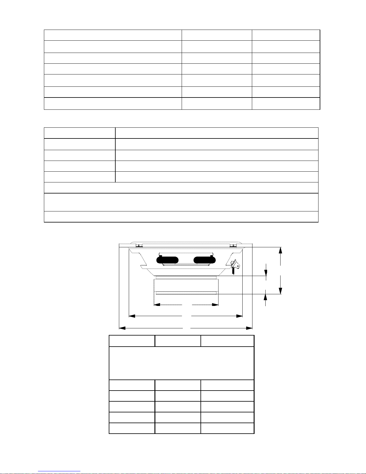
removing the surface mount tweeter assembly trim ring, route the tweeter wires
through the larger hole in the housing and connect to the speaker wires from the
crossover
.
(see figure 4
.
)
step
6: Insert the excess speaker wire into the hole and position the housing so the housing
will not pinch the wires after final mounting
.
step
7:
attach
the housing using the supplied screws of the correct length for a solid mount
.
step
8: Insert the tweeter into the housing and attach the surface mount trim ring
.
Surface
Mount
Trim Ring
Mounting
Screws
Surface Mount Housing
figure
4
figura
4
a
bbildung 4
Tweeter
Tweeter
Wire
Panel
Wiring
Harness
full
flus
H M
oun
TI
n
G
step 1:
.
Determine where the tweeter will be mounted
.
Make sure there is a flat area large
enough for the tweeter and no obstructions behind the area
.
step
2: using the back half of the tweeter housing, mark with a pen the hole needed for the
tweeter
.
step
3: be sure the hole is large enough for the tweeter housing, but not so large that the
flange will not cover the hole
. .
step
4: Cut the hole for the tweeter
.
When using factory locations, this step can be skipped
.
a
hole can be cut either with a pair of metal tin snips or a 1-7/8" hole saw for hard
materials
.
WARNING: Check for clearance of window mechanisms and electrical wires befoRe you drill
.

step
5: Install tweeter in flush mount housing
.
step
6: Connect the speaker wires observing the correct polarity
.
step
7: Install tweeter and housing in the hole cut for mounting, so that the trim ring is flat
with the front of the surface
.
step
8: use the supplied pressure ring to secure the housing to the surface
.
Flush
Mount
Tweeter
Assembly
Tweeter
Cup Pressure
Ring
figure
5
figura
5
a
bbildung 5
Flush Mount
Trim Ring
Tweeter
Wire
Panel
Wiring
Harness
Ins
t
all
i
n
g The Cr
osso
ver
step
1:
find
a location for the crossover away from any factory or after market electrical wires
.
It is recommended to mount the passive crossover close to the amplifier
.
step
2: Mount the crossover using the supplied wire ties
.
step
3: Connect the wires
.
Make sure the speaker wires for the midrange go to the mid/
woofer output and the tweeter to the tweeter output
.
be sure to observe the correct
polarity
.
Changing the polarity of the tweeter may be necessary for optimum sound
quality
.

Wiring Di
a
gr
a
m
Input
To Amplifier
Output
+
_
To woofer +
_
To tweeter +
_
Note: The tweeter positive is the wire marked with the stripe.
Note: Le câble positif du haut-parleur d'aigus est rayé.
Nota. El positivo del tweeter es el cable que tiene la franja.
Hinweis: Der positive Hochtönerdraht ist mit dem Streifen markiert.
Nota: il filo positivo del tweeter è contrassegnato da una striscia.
Nota: O cabo positivo do tweeter está marcado com a listra.
figure
6
figura
6
a
bbildung 6

CO552 CO652
Dimensions inches/mm, Dimensions pouces/mm,
Dimensiones plg
.
/mm,
a
bmessungen Zoll/mm,
Dimensioni pollici/millimetri, Dimensões
polegadas/mm
a
1
.
97/50 2
.
36/60
b0
.
71/18 0
.
91/23
C2
.
76/70 3
.
15/80
D4
.
72/120 5
.
63/143
e5
.
12/130 6
.
50/165
Sp
eci
f
ic
a
ti
ons
Model/Part number C
o
552 C
o
652
nominal Impedance 4 ohm 4 ohm
Power Continuous/Maximum 40 /100 w 50 /120 w
f
requency Response 120 -20kHz 60 - 20kHz
s
ensitivity 87db 85db
Mounting Depth 1
.
97"/50mm 2
.
36"/60mm
Mounting Diameter 4
.
72"/120mm 5
.
63"/143mm
f
ea
T
u
R
es
Cone moisture and uV resistant paper cone
s
urround nbR (nitrile butadiene rubber)
Voice Coil 2 layer copper clad aluminum wire on a kapton former
Tweeter metalized PeI (Polyetherimide) -
f
errofluid
s
pider single interlaced Conex
s
tamped steel baskets with euro mounting configurations
Two way systems have custom crossover with 6 db high pass, 6 db low pass and tweeter
protection
swivel
tweeter
noTe:
all
s
pecifications are subject to change without notice
.
A
B
figure
7
C
figura
7
D
a
bbildung 7
E
F
G
Orion Car Audio Speaker System
Other manuals for Cobalt CO552
3
This manual suits for next models
1
Table of contents
Other Orion Speakers manuals

Orion
Orion Cobalt CO552 User manual

Orion
Orion HCCA64N User manual

Orion
Orion CO400C User manual

Orion
Orion Cobalt C0500 User manual

Orion
Orion Cobalt CO552 User manual

Orion
Orion XTX64 User manual

Orion
Orion HCCA 5.2 User manual

Orion
Orion HCCA10d User manual

Orion
Orion XTR55.SC User manual

Orion
Orion Component Speaker XTR52 User manual