Orion Component Speaker XTR52 User manual

Component
Speaker
MODEL
XTR52
XTR62
OWNER'S
MANUAL


© 2012 MD Audio Engineering—all rights reserved
1
TABLE OF CONTENTS
English . . . . . . . . . . . . . . . . . . . . . . . . . . . . . . . . . . . . . . . . . . . . . . . . . . . . . . . . . . . . . . . . . . . . . . . . 1
Français . . . . . . . . . . . . . . . . . . . . . . . . . . . . . . . . . . . . . . . . . . . . . . . . . . . . . . . . . . . . . . . .9
Español . . . . . . . . . . . . . . . . . . . . . . . . . . . . . . . . . . . . . . . . . . . . . . . . . . . . . . . . . . . . . . .13
Deutsch . . . . . . . . . . . . . . . . . . . . . . . . . . . . . . . . . . . . . . . . . . . . . . . . . . . . . . . . . . . . . . .17
Italiano . . . . . . . . . . . . . . . . . . . . . . . . . . . . . . . . . . . . . . . . . . . . . . . . . . . . . . . . . . . . . . .21
Português . . . . . . . . . . . . . . . . . . . . . . . . . . . . . . . . . . . . . . . . . . . . . . . . . . . . . . . . . . . . .25
Introduction. . . . . . . . . . . . . . . . . . . . . . . . . . . . . . . . . . . . . . . . . . . . . . . . . . . . . . . . . . . . . . . . . . . . 1
Practice Safe Sound™ . . . . . . . . . . . . . . . . . . . . . . . . . . . . . . . . . . . . . . . . . . . . . . . . . . . . . . . . . . . . 1
What’s in the Box . . . . . . . . . . . . . . . . . . . . . . . . . . . . . . . . . . . . . . . . . . . . . . . . . . . . . . . . . . . . . . . 2
Tools of the Trade . . . . . . . . . . . . . . . . . . . . . . . . . . . . . . . . . . . . . . . . . . . . . . . . . . . . . . . . . . . . . . . 2
Installation. . . . . . . . . . . . . . . . . . . . . . . . . . . . . . . . . . . . . . . . . . . . . . . . . . . . . . . . . . . . . . . . . . . . . 2
Finding Speaker Mounting Locations . . . . . . . . . . . . . . . . . . . . . . . . . . . . . . . . . . . . . . . . . . . . . . . 2
Door Mounting . . . . . . . . . . . . . . . . . . . . . . . . . . . . . . . . . . . . . . . . . . . . . . . . . . . . . . . . . . . . . . . . . 3
Rear Deck Mounting. . . . . . . . . . . . . . . . . . . . . . . . . . . . . . . . . . . . . . . . . . . . . . . . . . . . . . . . . . . . . 3
Installing the Mid/Woofers. . . . . . . . . . . . . . . . . . . . . . . . . . . . . . . . . . . . . . . . . . . . . . . . . . . . . . . . 4
Installing the Tweeter. . . . . . . . . . . . . . . . . . . . . . . . . . . . . . . . . . . . . . . . . . . . . . . . . . . . . . . . . . . . 5
Installing the Crossover . . . . . . . . . . . . . . . . . . . . . . . . . . . . . . . . . . . . . . . . . . . . . . . . . . . . . . . . . . 6
Tweeter level controls. . . . . . . . . . . . . . . . . . . . . . . . . . . . . . . . . . . . . . . . . . . . . . . . . . . . . . . . . . . . 6
Wiring Diagram. . . . . . . . . . . . . . . . . . . . . . . . . . . . . . . . . . . . . . . . . . . . . . . . . . . . . . . . . . . . . . . . . 7
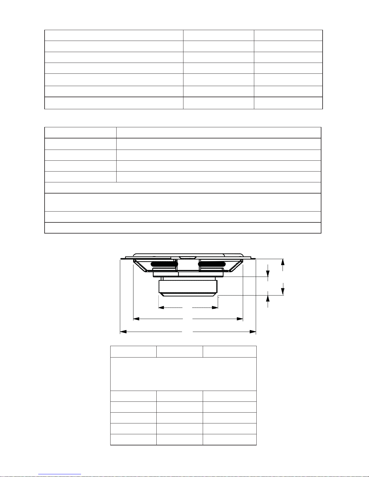
Specifications. . . . . . . . . . . . . . . . . . . . . . . . . . . . . . . . . . . . . . . . . . . . . . . . . . . . . . . . . . . . . . . . . . . 8
Features . . . . . . . . . . . . . . . . . . . . . . . . . . . . . . . . . . . . . . . . . . . . . . . . . . . . . . . . . . . . . . . . . . . . . . . 8
Warranty . . . . . . . . . . . . . . . . . . . . . . . . . . . . . . . . . . . . . . . . . . . . . . . . . . . . . . . . . . . . . . back cover
INTRODUCTION
Thank you for your purchase of the Orion XTR Component Loudspeaker system. These speakers
represent a combination of incredible performance and value. The Orion stamped steel frame
components feature treated paper cones and silk dome tweeters. Capable of maintaining their
balance and clarity at exceptionally high output levels, they are the perfect complement to the
Orion woofers. The crossovers feature tweeter level adjustment. The components are available
in standard 5-1/4" and 6-1/2" sizes to fit most applications.
We at Orion strive to give you all the latest up to date information about this product. What we
can't give you in this manual is personal installation or technical experience. If you have questions
concerning the use or application of this product, please refer to the nearest Authorized Orion
Dealer for assistance or call the Orion technical support hot-line at 1-800-876-0800. As we are
always finding new ways to improve our product, the features and specifications are subject to
change without notice.
PRACTICE SAFE SOUND™
Continuous exposure to sound pressure levels over 100dB may cause permanent hearing loss.
High powered automotive sound systems can generate sound pressure levels in excess of 130dB.
When playing your system at high levels, please use hearing protection and prevent long term
exposure.

2
© 2012 MD Audio Engineering—all rights reserved
Model Number:
Serial Number:
Date of Purchase:
WHAT’S IN THE BOX
Included in this box are all the necessary mounting hardware and cables for your basic
installation. Listed below is a detailed list of the components included in this system package.
Quantity Description
1 Owner's Manual
2 Orion Tweeter Elements
2 Surface mount hardware
2 Flush mount hardware
2 Orion mid/woofer speakers
2 Passive crossovers with cables
1 Mounting template
2 Grilles
Mounting screws
TOOLS OF THE TRADE
Listed are the majority of the tools required to perform the installation. Having the proper tools
will make the installation much easier. It is very difficult when you get half way through the
installation and discover that you require a specific tool to get yourself through a particular part
of the installation. Some of these tools are necessities. Some make the job much easier.
o Marking Pen o Electric Drill
o 1/4" Drill Bit o Phillips Screwdriver
o 1/8" Drill Bit o Volt/Ohm Meter (Optional)
o 3/8" Drill Bit o Needle Nose Pliers
o Hole Saw Arbor o Assorted Tin Snips
o Wire Crimpers o Wire Strippers
o 4-3/4" Hole Saw (5-1/4" mid/woofer install)
o 5" Hole Saw (6-1/2" mid/woofer install)
o 2" Hole Saw (for flush mount tweeter installation)
INSTALLATION
The performance of the Orion Component Loudspeaker is directly proportional to the quality of
installation. Care taken during the installation process will be rewarded with years of satisfying
performance. If you are unsure about your installation capabilities, please refer to your local
Authorized Orion Dealer for technical assistance. Orion dealers are trained professionals
dedicated to extracting the maximum performance out of your Orion system. If you decide to
install this speaker system yourself, please read the entire installation section before starting
your installation.
FINDING SPEAKER MOUNTING LOCATIONS
Choosing the correct speaker locations will have the greatest effect on the sound quality of the
system. Different considerations are needed when choosing the locations that best suit your
needs. The locations must be large enough for the speakers to fit. Care is needed to ensure that

© 2012 MD Audio Engineering—all rights reserved
3
the location you have chosen will not affect any of the mechanical or electrical operations of
the vehicle.
Determining the best location for the speakers will depend on your cosmetic needs and your
vehicle's interior. If minimal intrusion in your vehicle is desired, factory speaker locations may
be the ticket for you. Placing the speaker in the factory location can often give very desirable
results.
DOOR MOUNTING
When checking for possible speaker locations in the doors, check the operation of the window
and all assemblies. There is also a stabilizer stop bar in between the door and the door jamb.
This bar prevents the door from opening too far. Many shade tree installers overlook this and
check for clearance only when the door is fully open.
Figure 1
Figura 1
Abbildung 1
Inside
of
Door
Speaker
installed
with no
gaps
or air
leaks
Dampening
on
top of
outer
door
skin
Speaker
cut
out
Door
Panel
Dampening
Mat
Grille
Screws
REAR DECK MOUNTING
In rear deck installations, check the operation of the trunk suspension springs or tension bars.
These tension bars move in the opening and closing of the trunk. You cannot be too cautious
during this part of the installation, In addition, do not locate the speakers too close to the back
of the rear deck. Installing the far screws will only be possible with the removal of the rear
window.
Figure 2
Figura 2
Abbildung 2
Rear Seat Rear/Trunk
of Car

4
© 2012 MD Audio Engineering—all rights reserved
INSTALLING THE MID/WOOFERS
Step 1: Determine where the speakers will be mounted. Make sure there is a flat area large
enough for the speakers to fit properly. An uneven mounting surface can damage the
driver.
Step 2: Check to make sure the space you have chosen for the speakers will not interfere with
the operation of the vehicle.
Step 3: Using the supplied template guide, mark the mounting hole and mounting screw hole
locations with a pen for each speaker.
Step 4: Cut the holes for the speaker. When using correctly sized factory locations, this step
can be passed. A hole can be cut either with a pair of metal tin snips, an air or jig saw,
or with a hole saw corresponding to the size of the midrange listed below.
o 4-3/4" Hole Saw (5-1/4" woofer installation)
o 5" Hole Saw (6-1/2" woofer installation)
WARNING: Check for clearance of window mechanisms and electrical wires BEFORE you drill.
Step 5: Run the speaker wire to the speakers. Make sure to keep wires away from sharp metal
or other edges. When passing through metal, use a protective grommet.
Step 6: Pre-drill mounting screw holes using a 1/8" drill bit.
WARNING: Check for clearance of window mechanisms and electrical wires BEFORE you drill.
Step 7: Pull the wire through the speaker opening and connect to the speaker. Be sure to
observe proper mid/woofer polarity during this process.
Step 8: Mount the speaker- Place the speaker and the grille in the installation hole. Align the
mounting screw holes and drive in the four mounting screws.
Screws
Speaker
Panel
Wiring
Harness
Figure 3
Figura 3
Abbildung 3

© 2012 MD Audio Engineering—all rights reserved
5
INSTALLING THE TWEETER
SURFACE MOUNTING
Step 1: Determine the tweeter mounting location, then route the wires from the crossover to
the tweeter location.
Step 2: Place the provided template or tweeter cup against the panel and mark the two holes
at the rear of the housing.
Step 3: Drill the smaller holes using a 1/8" drill bit. These are the mounting screw holes.
WARNING: Check for clearance of window mechanisms and electrical wires BEFORE you drill.
Step 4: Drill the larger off-center hole using a 3/8" drill bit, insert a grommet and route the
speaker wire from the crossover through the grommet.
Step 5: After removing the surface mount tweeter assembly trim ring, route the tweeter wires
through the larger hole in the housing and connect to the speaker wires from the
crossover. (See Figure 4.)
Step 6: Insert the excess speaker wire into the hole and position the housing so the housing
will not pinch the wires after final mounting.
Step 7: Attach the housing using the supplied screws of the correct length for a solid mount.
Step 8: Insert the tweeter into the housing and attach the surface mount trim ring.
Surface
Mount
Trim Ring
Mounting
Screws
Surface Mount Housing
Figure 4
Figura 4
Abbildung 4
Tweeter
Tweeter
Wire
Panel
Wiring
Harness
FULL FLUSH MOUNTING
Step 1:. Determine where the tweeter will be mounted. Make sure there is a flat area large
enough for the tweeter and no obstructions behind the area.
Step 2: Using the back half of the tweeter housing, mark with a pen the hole needed for the
tweeter.
Step 3: Be sure the hole is large enough for the tweeter housing, but not so large that the
flange will not cover the hole..
Step 4: Cut the hole for the tweeter. When using factory locations, this step can be skipped.
A hole can be cut either with a pair of metal tin snips or a 2" hole saw for hard
materials.
WARNING: Check for clearance of window mechanisms and electrical wires BEFORE you drill.

6
© 2012 MD Audio Engineering—all rights reserved
Step 5: Install tweeter in flush mount housing.
Step 6: Connect the speaker wires observing the correct polarity.
Step 7: Install tweeter and housing in the hole cut for mounting, so that the trim ring is flat
with the front of the surface.
Step 8: Use the supplied X bracket & screw to secure the housing to the surface.
Flush
Mount
Tweeter
Assembly
Screw
Tweeter
Cup
X Bracket
Figure 5
Figura 5
Abbildung 5
Flush
Mount
Trim
Ring
Tweeter
Wire
Panel
Wiring
Harness
INSTALLING THE CROSSOVER
Step 1: Find a location for the crossover away from any factory or after market electrical wires.
It is recommended to mount the passive crossover close to the amplifier.
Step 2: Mount the crossover using the supplied screws.
Step 3: Connect the wires. Make sure the speaker wires for the midrange go to the mid/
woofer output and the tweeter to the tweeter output. Be sure to observe the correct
polarity. Changing the polarity of the tweeter may be necessary for optimum sound
quality.
TWEETER LEVEL CONTROLS
The three position switch in the crossover box labeled “TW Level” adjusts the relative volume
of the tweeter with respect to the midrange. The 0db position is referenced as equal output
from the midrange and the tweeter. The -3dB and +3dB positions offer -3dB less and +3dB more
output from the tweeter respectively. Tweeter level can be adjusted independently for right and
left channels to compensate for different listening tastes and mounting locations.

© 2012 MD Audio Engineering—all rights reserved
7
WIRING DIAGRAM
Input
Crossover
To Amplifier
Output
+
_
To Woofer +
_
To Tweeter +
_
Note: The tweeter positive is the wire marked with the stripe.
Note: Le câble positif du haut-parleur d'aigus est rayé.
Nota. El positivo del tweeter es el cable que tiene la franja.
Hinweis: Der positive Hochtönerdraht ist mit dem Streifen markiert.
Nota: il filo positivo del tweeter è contrassegnato da una striscia.
Nota: O cabo positivo do tweeter está marcado com a listra.
Figure 6
Figura 6
Abbildung 6

8
© 2012 MD Audio Engineering—all rights reserved
SPECIFICATIONS
Model
XTR52
XTR62
Nominal Impedance
4 Ω
4 Ω
Power Continuous/Maximum
50 /100 W
60 /120 W
Frequency Response
80 - 22kHz
75 - 22kHz
Sensitivity (2.83V @ 1M)
88dB
90dB
Mounting Depth
2.29"/58mm
2"/51mm
Mounting Diameter
4.72"/120mm
5"/127mm
FEATURES
Cone
moisture and UV resistant paper cone
Surround
Butyl rubber
Voice Coil
2 layer copper wire on a Kapton former
Tweeter
silk dome - Ferrofluid
Spider
single interlaced Conex
Stamped steel baskets with Euro mounting configurations
Two way systems have custom crossover with 12 dB high pass, 6 dB low pass and tweeter
protection
Swivel tweeter
3 position tweeter level adjustment switch (-3dB, 0dB & +3dB)
NOTE: All Specifications are subject to change without notice.
A
B
C
Figure 7
D
Figura 7
Abbildung 7
E
XTR52
XTR62
Dimensions inches/mm, Dimensions pouces/mm,
Dimensiones plg./mm, Abmessungen Zoll/mm,
Dimensioni pollici/millimetri, Dimensões
polegadas/mm
A
2.29/58
2/51
B
0.91/23
0.79/20
C
2.76/70
3.19/81
D
4.72/120
5/127
E
5.16/131
6.50/165

o Scie-cloche 5" (installation d'un haut-parleur de graves de 6-1/2")
© 2012 MD Audio Engineering—Tous droits réservés
9
FRANÇAIS
OÙ MONTER LES HAUT-PARLEURS
Le choix du bon emplacement des haut-parleurs aura un effet majeur sur la qualité du son du
système. Plusieurs choses doivent être prises en considération pour faire le meilleur choix. Les
emplacements doivent être assez grands pour accueillir les haut-parleurs. Faites attention que
l'emplacement choisi n'affecte en aucune façon le fonctionnement mécanique et électrique du
véhicule.
Le meilleur emplacement pour les haut-parleurs dépend de vos goûts et de l'aménagement
intérieur du véhicule. Si vous voulez une installation aussi discrète que possible, les emplacements
prévus par le fabricant sont sans doute le meilleur choix. Cela donnera souvent d'excellents
résultats.
MONTAGE SUR UNE PORTIÈRE
Quand vous recherchez une location possible pour installer vos haut-parleurs dans les portières,
vérifiez le fonctionnement de la fenêtre et de tous les mécanismes. Vérifiez aussi la barre
stabilisatrice entre la portière et son montant. Elle empêche la portière de s'ouvrir trop grand.
Beaucoup d'installateurs inexpérimentés négligent ce détail et ne vérifient l'espace libre que
quand la porte est grand ouverte (figure 1).
MONTAGE DANS LE COFFRE
Pour une installation dans le coffre, vérifiez le fonctionnement des ressorts de suspension ou
barres de tension du coffre. Ces barres se déplacent durant l'ouverture et la fermeture du coffre.
On n'est jamais trop prudent durant cette partie de l'installation. De plus, ne placez pas les haut-
parleurs trop près de l'arrière du coffre. L'installation des vis les plus écartées n'est possible que
si on retire la vitre arrière (figure 2).
INSTALLATION DES HAUT-PARLEURS MÉDIAUX ET DE
GRAVES
Étape 1: Décidez où fixer les haut-parleurs et assurez-vous qu'il y ait une surface plane suffisante
pour bien les fixer. Une surface de montage inégale peut endommager le moteur.
Étape 2: Assurez-vous que l'emplacement choisi pour les haut-parleurs n'interfère pas avec le
fonctionnement du véhicule.
Étape 3: Au moyen du gabarit de montage fourni et d'un crayon, marquez l'emplacement des
trous de montage et des vis de montage pour chaque haut-parleur.
Étape 4: Découpez les trous pour le haut-parleur. Si vous utilisez les emplacements prévus par le
fabricant et qu'ils sont de la bonne dimension, cette étape peut être sautée. Utilisez
soit une paire de cisailles à tôles, une scie pneumatique ou sauteuse, ou une scie-cloche
de la taille correspondant à celle ci-dessous.
o Scie-cloche 4-3/4" (installation d'un haut-parleur de graves de 5-1/4")

10
© 2012 MD Audio Engineering—Tous droits réservés
ATTENTION: Vérifiez l'espace libre du mécanisme et des fils électriques des fenêtres AVANT de
percer.
Étape 5: Amenez les câbles à leurs haut-parleurs. Assurez-vous de les garder loin de tout bord
métallique ou autre aiguisé. Pour passer à travers le métal, utilisez une rondelle
isolante.
Étape 6: Pré-percez les trous de vis de montage avec une mèche 1/8".
ATTENTION: Vérifiez l'espace libre du mécanisme et des fils électriques des fenêtres AVANT de
percer.
Étape 7: Faites passer le câble par l'ouverture du haut-parleur et raccordez-le. Assurez-vous de
respecter la polarité du haut-parleur médial et de graves.
Étape 8: Montez le haut-parleur — Placez-le avec sa grille dans le trou d'installation. Alignez les
trous des vis de montage et vissez les quatre vis.
INSTALLATION DU HAUT-PARLEUR D'AIGUS
MONTAGE EN SURFACE
Étape 1: Décidez où fixer le haut-parleur d'aigus, puis amenez-y les câbles du répartiteur.
Étape 2: Placez le gabarit fourni ou le cône du haut-parleur d'aigus sur le panneau et marquez
les deux trous à l'arrière du logement.
Étape 3: Percez les petits trous avec une mèche 1/8". Ce sont les trous de montage.
ATTENTION: Vérifiez l'espace libre du mécanisme et des fils électriques des fenêtres AVANT de
percer.
Étape 4: Percez le grand trou excentré (mèche de 3/8"), insérez une rondelle isolante et faites-y
passer le câble du haut-parleur vers le répartiteur.
Étape 5: Ôtez la garniture de montage en surface, passez les câbles du haut-parleur d'aigus
par le grand trou du logement et raccordez aux câbles de haut-parleur du répartiteur
(figure 4.)
Étape 6: Insérez le câble de haut-parleur en trop dans le trou et placez le logement afin qu'il ne
pince pas les câbles après le montage final.
Étape 7: Pour un montage solide, utilisez les vis fournies de la bonne longueur pour attacher le
logement.
Étape 8: Insérez le haut-parleur d'aigus dans le logement et attachez la garniture.
MONTAGE ENCASTRÉ
Étape 1: Décidez où fixer le haut-parleur d'aigus et assurez-vous qu'il y ait une surface plane
suffisante pour bien le fixer, sans obstructions à l'arrière de la surface.
Étape 2: Marquez le trou de montage nécessaire à l'aide d'un crayon et de la moitié arrière du
logement du haut-parleur.
Étape 3: Assurez-vous que le trou est assez grand pour le logement du haut-parleur, mais pas trop
grand pour être couvert par la flasque.
Étape 4: Coupez le trou du haut-parleur (inutile si vous utilisez les emplacements prévus par le
fabricant). Utilisez des cisailles à tôles ou une scie-cloche 2" pour les matériaux durs.
ATTENTION: Vérifiez l'espace libre du mécanisme et des fils électriques des fenêtres AVANT de
percer.
Étape 5: Installez le haut-parleur dans le logement encastré.
Étape 6: Raccordez les câbles du haut-parleur en respectant la polarité.
Étape 7: Installez le haut-parleur et le logement dans le trou découpé pour le montage, afin que
la garniture soit au niveau de l'avant de la surface.

© 2012 MD Audio Engineering—Tous droits réservés
11
Étape 8: Utilisez le support en croix et la vis inclus pour fixer le boîtier sur la surface..
INSTALLATION DU RÉPARTITEUR
Étape 1: Décidez où fixer le répartiteur, loin de tout fil électrique, d'origine ou installé après
coup. Le répartiteur passif devrait être monté à proximité de l'amplificateur.
Étape 2: Montez le répartiteur à l’aide des vis fournies.
Étape 3: Raccordez les câbles. Assurez-vous que les câbles du haut-parleur médial vont à la sortie
médial/graves et ceux du haut-parleur d'aigus à la sortie des aigus. Assurez-vous de
respecter la polarité. Changer celle du haut-parleur d'aigus peut être requis pour une
qualité sonore optimale.
NOTE: Diagramme de référence aux pages 4 - 7 (figure 3, 4, 5, 6)
RÉGLAGE DU NIVEAU DE HAUT-PARLEURS D’AIGUS
Le commutateur à trois positions repéré « TW Level » (niveau haut-parleur d’aigus) sur le boîtier
du répartiteur permet de régler le volume relatif du haut-parleur d’aigus par rapport à celui
du haut-parleur de médiums. La position 0 dB correspond à des niveaux identiques du haut-
parleur de médiums et du haut-parleur d’aigus. Les positions –3 dB et +3 dB correspondent
respectivement à –3 dB et +3 dB de niveau pour le haut-parleur d’aigus. Le niveau du haut-
parleur d’aigus peut être réglé indépendamment pour les canaux gauche et droit, afin de tenir
compte des différentes préférences d’écoute et d’emplacement de montage.
SPÉCIFICATIONS
Modèle
XTR52
XTR62
Impédance nominale
4 ohm
4 ohm
Puissance continue/maximum
50 /100 W
60 /120 W
Réponse de fréquence
80 - 22kHz
75 - 22kHz
Sensitivité (2.83V @ 1M)
88dB
90dB
Profondeur de montage (pouces/mm)
2.29"/58mm
2"/51mm
Diamètre de montage (pouces/mm)
4.72"/120mm
5"/127mm
CARACTÉRISTIQUES
Cône
Papier résistant à l'humidité et aux ultraviolets
Boîtier
Caoutchouc butyle
Bobine acoustique
Fil de cuivre 2 couches sur manchon Kapton
Haut-parleur d'aigus
Dôme de soie – Ferrofluid
Anneau de centrage
Conex simple entrelacé
Paniers en acier matricé avec configuration de montage européen
Systèmes bidirectionnels avec répartiteur personnalisé: passe-haut 6 dB, passe-bas 6 dB et
protection du haut-parleur d'aigus
Haut-parleur d'aigus orientable
Commutateur de réglage de niveau à 3 positions (–3 dB, 0 dB et +3 dB)
NOTE: Toutes spécifications sujettes à changement sans préavis.

© 2012 MD Audio Engineering—Reservados todos los derechos.
12
ESPAÑOL
UBICACIONES DE MONTAJE DE LOS ALTAVOCES
Escoger la ubicación correcta de los altavoces tendrá el mayor efecto en la calidad del sonido
del sistema. Es necesario que usted tenga en cuenta varias consideraciones cuando escoja el
lugar que mejor se adapte a sus necesidades. Los lugares escogidos deben ser lo suficientemente
grandes como para que quepan los altavoces. Es necesario que en la ubicación escogida no se
afecte ninguna operación mecánica o eléctrica del vehículo.
Determinar la mejor ubicación de los altavoces depende de sus necesidades cosméticas y del
interior del vehículo. Si desea interferir lo menos posible con el vehículo, las ubicaciones de
altavoz de fábrica son ideales. Colocar el altavoz en la ubicación de fábrica puede a menudo dar
muy buenos resultados.
MONTAJE EN LA PUERTA
Cuando esté buscando posibles ubicaciones de altavoz en las puertas, verifique el funcionamiento
de las ventanas y de todos los mecanismos de las puertas. También hay una barra de tope
estabilizadora entre la puerta y la jamba de la puerta. Esta barra evita que la puerta se abra
demasiado. Muchos instaladores informales olvidan esto y verifican que haya espacio sólo
cuando la puerta está completamente abierta (figura 1).
MONTAJE EN LA REPISA TRASERA
En las instalaciones en repisa trasera, verifique el funcionamiento de los resortes de suspensión o
barras de tensión de la tapa del maletero. Estas barras de tensión se mueven cuando se abre o se
cierra el maletero. Ser precavido nunca está de más durante esta parte de la instalación. Además,
no ubique los altavoces demasiado cerca del fondo de la repisa trasera. Montar los tornillos del
fondo será posible solamente quitando la ventana trasera (figura 2).
INSTALACIÓN DE LOS ALTAVOCES DE FRECUENCIAS MEDIAS
Y BAJAS
Paso 1: Determine el lugar en que va a montar los altavoces. Debe haber una superficie plana
suficientemente grande como para que los altavoces encajen correctamente. Las
superficies de montaje irregulares pueden dañar el excitador.
Paso 2: Verifique que, en el lugar escogido, el altavoz no interfiera con el funcionamiento del
vehículo.
Paso 3: Con la plantilla guía suministrada y un lápiz, marque el agujero de montaje del altavoz
y los agujeros de los tornillos de montaje de los altavoces.
Paso 4: Haga los agujeros para los altavoces. Cuando instale los altavoces en ubicaciones de
fábrica, este paso se puede omitir. El agujero se puede hacer con unas tijeras para cortar
metal, una sierra caladora o una sierra circular que corresponda al tamaño del altavoz
de frecuencias medias que se indica abajo.


14
© 2012 MD Audio Engineering—Reservados todos los derechos.
* Sierra circular de 4 3/4 plg. (woofer de 5 1/4 plg.)
* Sierra circular de 5 plg. (woofer de 6 1/2 plg.)
ADVERTENCIA: Verifique que haya espacio para los mecanismos de ventana y los cables
eléctricos ANTES de taladrar.
Paso 5: Encamine el cable de altavoz hasta los altavoces. Mantenga los cables de altavoz lejos
de los bordes afilados de metal u otro material. Cuando pase los cables a través de
metal, ponga en el agujero una arandela de goma protectora.
Paso 6: Haga de antemano los agujeros de montaje con una broca perforadora de 1/8 de plg.
ADVERTENCIA: Verifique que haya espacio para los mecanismos de ventana y los cables eléctricos
ANTES de taladrar.
Paso 7: Jale el cable a través de la abertura del altavoz y conéctelo al altavoz. Mantenga
la polaridad correcta de los altavoces de frecuencias medias y bajas durante este
proceso.
Paso 8: Monte el altavoz. Coloque el altavoz y la rejilla en el agujero de instalación. Alinee los
agujeros de los tornillos de montaje y atornille los cuatro tornillos de montaje.
INSTALACIÓN DEL TWEETER
MONTAJE EN SUPERFICIE
Paso 1: Determine la ubicación de montaje del tweeter y luego encamine los cables
provenientes del crossover hasta la ubicación del tweeter.
Paso 2: Ponga la plantilla suministrada o la copa del tweeter contra el panel y marque los dos
agujeros en la parte de atrás del alojamiento.
Paso 3: Haga los agujeros pequeños con una broca de 1/8 plg. Estos son los agujeros de los
tornillos de montaje.
ADVERTENCIA: Verifique que haya espacio para los mecanismos de ventana y los cables eléctricos
ANTES de taladrar.
Paso 4: Haga el agujero grande excéntrico con una broca perforadora de 3/8 plg., inserte una
arandela de goma y encamine el cable de altavoz proveniente del crossover a través de
la arandela de goma.
Paso 5. Después de quitar el anillo de guarnición de la unidad de tweeter para montaje en
superficie, encamine los cables del tweeter a través del agujero grande que hay en el
alojamiento y conecte los cables de altavoz provenientes del crossover (vea la Figura
4).
Paso 6. Inserte el exceso de cable de altavoz en el agujero y ponga en posición el alojamiento
de manera que no vaya a aplastar los cables después del montaje final.
Paso 7. Fije el alojamiento con los tornillos suministrados de la longitud correcta para lograr un
montaje sólido.
Paso 8. Inserte el tweeter en el alojamiento y fije el anillo de guarnición de montaje en
superficie.
MONTAJE AL RAS
Paso 1. Determine dónde va a montar el tweeter. Debe haber una superficie plana lo
suficientemente grande como para que quepa el tweeter y no debe haber obstrucciones
detrás.
Paso 2. Con la parte de atrás del alojamiento del tweeter y un lápiz, marque el agujero
necesario para el tweeter.
Paso 3. El agujero debe ser lo suficientemente grande como para que quepa el alojamiento del
tweeter, pero no tanto que el reborde no cubra el agujero.

© 2012 MD Audio Engineering—Reservados todos los derechos.
15
Paso 4. Haga el agujero para el tweeter. Cuando instale el tweeter en ubicaciones de fábrica,
este paso se puede omitir. Se puede hacer el agujero con unas tijeras de metal o una
sierra circular de 2 plg. para materiales duros.
ADVERTENCIA: Verifique que haya espacio para los mecanismos de ventana y los cables eléctricos
ANTES de taladrar.
Paso 5. Instale el tweeter en el alojamiento de montaje al ras.
Paso 6. Conecte los cables de altavoz con la polaridad correcta.
Paso 7. Instale el tweeter y el alojamiento en el agujero de montaje de manera que el anillo de
guarnición quede de plano contra la superficie exterior.
Paso 8. Con el soporte en X y el tornillo suministrados, asegure el alojamiento contra la
superficie.
INSTALACIÓN DEL CROSSOVER
Paso 1. Escoja una ubicación lejos de cables eléctricos de posventa o de fábrica para el
crossover.Se recomienda montar el crossover pasivo cerca del amplificador.
Paso 2. Monte el crossover con los tornillos suministrados.
Paso 3. Conecte los cables. Asegúrese de que los cables para el altavoz de frecuencias medias
vayan a la salida de frecuencias medias y bajas y los del tweeter a la salida de tweeter.
Mantenga la polaridad correcta. Puede ser necesario cambiar la polaridad del tweeter
para lograr una calidad de sonido óptima.
Consulte el diagrama de las páginas 4 - 7 (figura 3, 4, 5, 6).
CONTROLES DE NIVEL DE TWEETER
El selector "TW Level" de tres posiciones de la caja de crossover permite ajustar el volumen
relativo del tweeter con respecto al volumen del altavoz de frecuencias medias. La posición 0dB
produce una salida de altavoz de frecuencias medias igual a la del tweeter. Las posiciones -3dB y
+3dB producen respectivamente 3dB menos y 3dB más de salida de tweeter. El nivel del tweeter
se puede ajustar independientemente en los canales derecho e izquierdo para adaptarse a los
diferentes gustos de audición y ubicaciones de montaje.
ESPECIFICACIONES
Modelo
XTR52
XTR62
Impedancia nominal
4 ohm
4 ohm
Potencia continua/máxima
50 /100 W
60 /120 W
Respuesta de frecuencias
80 - 22kHz
75 - 22kHz
Sensibilidad (2.83V @ 1M)
88dB
90dB
Profundidad de montaje (plg/mm)
2.29"/58mm
2"/51mm
Diámetro de montaje (plg/mm)
4.72"/120mm
5"/127mm
CARACTERÍSTICAS
Cono
cono de papel resistente a la humedad y los rayos ultravioleta
Envolvente
Goma de butilo

16
© 2012 MD Audio Engineering—Reservados todos los derechos.
Bobina de voz
Alambre de cobre de 2 capas en un formador Kapton
Tweeter
Domo de seda - Ferrofluido
Araña
Conex entrelazado de una pieza
Canastas de acero troquelado con configuraciones de montaje Euro
Los sistemas de dos canales tienen crossover a la medida con pasaaltas de 6 dB, pasabajas de
6 dB y protección de tweeter
Tweeter oscilante
Selector de tres posiciones (-3dB, 0dB y +3dB) de ajuste de nivel de tweeter
NOTA: Todas las especificaciones están sujetas a cambios sin aviso previo.

© 2012 MD Audio Engineering—Alle Rechte vorbehalten
17
DEUTSCH
SO PLATZIEREN SIE DIE LAUTSPRECHER
Die Wahl der korrekten Lautsprecherposition hat große Auswirkungen auf die Soundqualität
des Systems. Bei der Wahl der Lautsprecherposition, die Ihren Ansprüchen am besten entspricht,
sind mehrere Faktoren zu beachten. Es muss an der Stelle genügend Platz für den Lautsprecher
vorhanden sein. Sie müssen sicherstellen, dass die gewählte Stelle die mechanischen oder
elektrischen Funktionen des Fahrzeugs nicht beeinträchtigt.
Die Wahl der geeigneten Einbaustelle hängt sowohl von ästhetischen Faktoren als auch vom
Innenraum Ihres Fahrzeugs ab. Wenn Sie das Fahrzeug nur minimal verändern wollen, sind die
werksseitigen Einbaustellen am besten. Der Einbau an diesen Stellen kann oft zu sehr guten
Ergebnissen führen.
TÜREINBAU
Wenn Sie mögliche Lautsprechereinbaustellen in den Türen suchen, müssen Sie die Funktionen
der Fenster und aller Baugruppen beachten. Zwischen der Tür und der Türschwelle befindet
sich eine Stabilisator-Anschlagleiste. Diese Leiste verhindert, dass die Tür sich zu weit öffnet.
Viele Amateur-Einbauer übersehen das und prüfen nur den Freiraum bei voll geöffneter Tür
(abbildung 1).
EINBAU IM KOFFERRAUM
Beim Einbau im Kofferraum ist auf die Funktionsfähigkeit der Kofferraumfedern oder Zugstäbe
zu achten. Diese Zugstäbe bewegen sich beim Öffnen und Schließen des Kofferraums. Seien Sie
bei diesem Teil der Installation besonders vorsichtig und platzieren Sie die Lautsprecher auch
nicht zu nahe an der Kofferraumhinterkante. Der Einbau der hinteren Schrauben ist erst nach
Ausbau des Rückfensters möglich (abbildung 2).
EINBAU DER MITTEL-/TIEFTÖNER
1. Schritt: Legen Sie fest, wo die Lautsprecher eingebaut werden. Vergewissern Sie sich, dass eine
für den fachgemäßen Einbau ausreichende ebene Fläche vorhanden ist. Eine unebene
Oberfläche kann den Treiber beschädigen.
2. Schritt: Stellen Sie sicher, dass die gewählte Stelle den Betrieb des Fahrzeugs auf keine Weise
behindert.
3. Schritt: Verwenden Sie die beiliegende Schablone und markieren Sie das Einbauloch und die
Positionen der Befestigungsschrauben für jeden Lautsprecher mit einem Stift.
4. Schritt: Schneiden Sie das jeweilige Loch für den Lautsprecher aus. Bei Verwendung der
werksseitigen Einbaustellen (die schon die richtige Größe haben) kann dieser Schritt
übersprungen werden. Man kann das Loch entweder mit einer Blechschere, einer
Pressluftsäge oder einer Stichsäge ausschneiden, je nach Größe des unten aufgelisteten
Mitteltöners.
* 4,75 Zoll Lochsäge (5,25 Zoll Tieftönerinstallation)
* 5 Zoll Lochsäge (6,5 Zoll Tieftönerinstallation)

18
© 2012 MD Audio Engineering—Alle Rechte vorbehalten
WARNUNG: Prüfen Sie VOR dem Bohren, dass Sie keine Fenstermechanismen oder Stromkabel
anbohren.
5. Schritt: Verlegen Sie die Lautsprecherkabel zu den Lautsprechern. Dabei müssen Sie die Kabel
von scharfen Metallkanten oder anderen Kanten entfernt halten. Bei der Verlegung
durch Metall ist eine Schutztülle zu verwenden.
6. Schritt: Bohren Sie die Befestigungsschraubenlöcher mit einem 1/8-Zoll-Bohrer vor.
WARNUNG: Prüfen Sie VOR dem Bohren, dass Sie keine Fenstermechanismen oder Stromkabel
anbohren.
7. Schritt: Ziehen Sie das Kabel durch die Lautsprecheröffnung und schließen Sie es an den
Lautsprecher an. Beachten Sie dabei, dass die Mitteltöner/Tieftöner richtig gepolt
sind.
8. Schritt: Bauen Sie den Lautsprecher ein. Platzieren Sie hierzu den Lautsprecher und den Grill
in der Einbauöffnung. Richten Sie die Befestigungsschraubenlöcher aus und ziehen Sie
die vier Befestigungsschrauben an.
EINBAU DES HOCHTÖNERS
OBERFLÄCHENEINBAU
1. Schritt: Legen Sie den Einbauort des Hochtöners fest und verlegen Sie dann die Kabel von der
Crossover-Einheit zum Einbauort.
2. Schritt: Legen Sie die beiliegende Schablone oder den Hochtönerbecher auf die Verkleidung
und markieren Sie die zwei Löcher an der Rückseite des Gehäuses.
3. Schritt: Bohren Sie die kleineren Löcher mit einem 1/8-Zoll-Bohrer. Das sind die
Befestigungsschraubenlöcher.
WARNUNG: Prüfen Sie VOR dem Bohren, dass Sie keine Fenstermechanismen oder Stromkabel
anbohren.
4. Schritt: Bohren Sie das größere Loch neben der Mitte mit einem 3/8-Zoll-Bohrer, stecken
Sie eine Schutztülle ein und verlegen Sie das von der Crossover-Einheit kommende
Lautsprecherkabel durch die Schutztülle.
5. Schritt: Nachdem Sie die Blende der Hochtöner-Oberflächeneinbaugruppe entfernt haben,
führen Sie die Hochtönerkabel durch das größere Loch im Gehäuse und schließen
Sie sie an die von der Crossover-Einheit kommenden Lautsprecherkabel an. (Siehe
Abbildung 4.)
6. Schritt: Führen Sie das nicht benötigte Lautsprecherkabel in das Loch ein und platzieren Sie das
Gehäuse so, dass es nach dem Endeinbau das Kabel nicht einklemmt.
7. Schritt: Bringen Sie das Gehäuse mit den beiliegenden Schrauben der richtigen Länge an, um
eine sichere Befestigung zu gewährleisten.
8. Schritt: Führen Sie den Hochtöner in das Gehäuse ein und bringen Sie die Blende für den
Oberflächeneinbau an.
BÜNDIGER EINBAU
1. Schritt: Legen Sie die Einbaustelle für den Hochtöner fest. Vergewissern Sie sich, dass eine für
den Einbau des Hochtöners ausreichende ebene Fläche vorhanden ist und dass sich
dahinter keine Hindernisse befinden.
2. Schritt: Verwenden Sie die Rückseite des Hochtönergehäuses, um das Loch für den Hochtöner
mit einem Stift zu markieren.
3. Schritt: Vergewissern Sie sich, dass das Loch für das Hochtönergehäuse groß genug ist, aber
nicht so groß, dass der Flansch das Loch nicht mehr abdeckt.
4. Schritt: Schneiden Sie das Loch für den Hochtöner aus. Bei Verwendung der werksseitigen
Einbaustellen kann dieser Schritt übersprungen werden. Sie können das Loch entweder
mit einer Blechschere oder einer 2-Zoll-Lochsäge für harte Oberflächen ausschneiden.
This manual suits for next models
1
Table of contents
Languages:
Other Orion Speakers manuals

Orion
Orion CO400C User manual

Orion
Orion COBALT CM65 User manual

Orion
Orion HCCA1002 User manual

Orion
Orion XTR55.SC User manual

Orion
Orion HCCA10d User manual

Orion
Orion Cobalt C0500 User manual

Orion
Orion Cobalt CO552 User manual

Orion
Orion XTR8S User manual

Orion
Orion HCCA 5.2 User manual

Orion
Orion Cobalt CO552 User manual