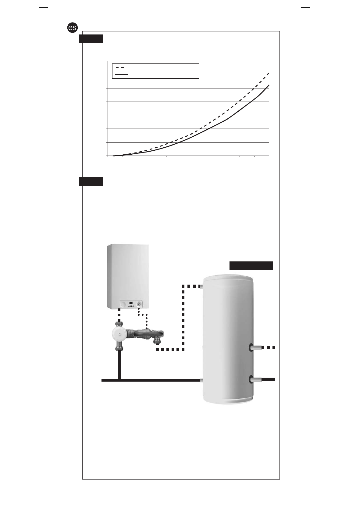
Orkli Solar Sanitary Kit User manual

KIT SANITARIO SOLAR
SOLAR SANITARY KIT
KIT SANITAIRE SOLAIRE
SOLAR- BRAUCHWASSER-KIT
SOLÁRNÍ SANITÁRNÍ KIT


3
1. Función 4
2. Componentes 4
3. Características técnicas 5
4. Características hidráulicas 6
5. Instalación 6
6. Garantía 7
1. Fonction 12
2. Pièces 12
3. Caractéristiques techniques 13
4. Caractéristiques hydrauliques 14
5. Installation 14
6. Garantie 15
1. Function 8
2. Components 8
3. Technical specifications 9
4. Hydraulic specifications 10
5. Installation 10
6. Guarantee 11
1. Beschreibung 16
2. Bestandteile 16
3. Technische Eigenschaften 17
4. Hydraulische Eigenschaften 18
5. Einbau 18
6. Garantie 19
&UNKCE
+OMPONENTY
4ECHNICKmPARAMETRY
(YDRAULICKmPARAMETRY
)NSTALACE
:fRUKA

4
1.
2.
FUNCIÓN
El “Kit Sanitario Solar” es un conjunto de conexión a los
equipos auxiliares de calentamiento de agua sanitaria
que se instalan entre el acumulador sanitario solar y esta
fuente de energía de apoyo: normalmente una caldera
instantánea, un calentador o un termo eléctrico.
Puesto que la acumulación sanitaria de solar no es estable
en temperatura, la entrada a la fuente de apoyo debe ser
regulada. De esta forma, el “Kit Sanitario Solar” se instala a la
entrada de esta fuente y regula automáticamente un by-pass
y la temperatura de salida del agua caliente sanitaria.
COMPONENTES
1. Válvula de 3 vías:
3347
25
135
180
Este componente es un elemento que decide si el
agua proveniente del acumulador solar debe pasar
por la fuente de apoyo o puede ser directamente
llevada a consumo.
a. Si la temperatura de entrada es >48ºC la válvula
de 3 vías bypassea la fuente de apoyo convencional
y lleva el agua de consumo directamente a la
mezcladora de salida.
b. Si la temperatura de entrada es <48ºC. La válvula
desactiva el bypass y hace circular el agua de
consumo por la fuente de apoyo. De esta forma
la fuente de calor adicional le dará a este agua el
aumento de temperatura necesario para que tenga
suficiente temperatura en la salida de sanitario.
Esta válvula es completamente estanca evitando de
esta forma que haya fuga alguna hacia el sistema de
apoyo cuando la temperatura del acumulador solar es
superior a la temperatura de desvío. Se evita así tener
una temperatura muy alta en la entrada de agua fría
del equipo auxiliar.
Válvula mezcladora Válvula de 3 vías

64
88 29
79
5
2. Válvula mezcladora:
La válvula mezcladora regulará la temperatura
de salida del agua caliente sanitaria del sistema
solar+apoyo convencional. Tanto si el flujo pasa por el
equipo de apoyo como si no, la alimentación de agua
caliente pasa por este elemento, con lo que se asegura
una temperatura controlada y estable a la salida.
Al poder tener temperaturas superiores a los 55ºC
en el acumulador de solar o a la salida de la fuente
convencional; la mezcladora evitará el riesgo de
quemaduras por temperaturas excesivamente
elevadas.
Válvula mezcladora
Válvula de 3 vías
3. CARACTERÍSTICAS TÉCNICAS
r .BUFSJBMWBMWVMFSÎBMBUÓOTFHÙOOPSNB&/
r .BUFSJBMKVOUBTEFDJFSSF&1%.
r $POFYJPOFTu.UVFSDBCJDPOPUVCPNNDVP
junta plana.
r 5FNQFSBUVSBNÃYJNBEFUSBCBKP$
r 1SFTJÓONÃYJNBEFUSBCBKPCBS
r 5BSBEP EF WÃMWVMB WÎBTUFNQFSBUVSB EF EFTWÎP
48ºC.
r 5PMFSBODJBUFNQFSBUVSBEFEFTWÎP± 2ºC.
r 3BOHP EF SFHVMBDJÓO EF NF[DMBEPSB UFSNPTUÃUJDB
30-60ºC.
r 5BSBEPEFUFNQFSBUVSBEFTBMJEBNF[DMBEPSB$
r ,WWÃMWVMBWÎBTN3I
r ,WWÃMWVMBNF[DMBEPSBN3I
r $PNQPOFOUFTBQUPTQBSBTVVTPDPOBHVBTBOJUBSJB

6
4.
5.
CARACTERÍSTICAS HIDRÁULICAS
INSTALACIÓN
Circuito caldera
Circuito directo a mezclador
3500
3000
2500
2000
1500
1000
500
0
0 200 400 600 800 1000 1200 1400 1600 1800 2000 2200
Caudal (l/h)
PÉRDIDAS DE CARGAVálvula 3 vías
Δ (mbar)
El Kit Sanitario Solar debe ser instalado entre el
acumulador de solar y el sistema de apoyo convencional.
La salida de agua caliente del acumulador de solar
deberá conectarse con la entrada del Kit Sanitario Solar:
El conexionado de las tomas se muestra en los siguientes
esquemas:
Acumulador solar

7
6. GARANTÍA
El Kit Sanitario Solar está garantizado contra todo defecto
de material durante 3 años a partir de la fecha de
fabricación marcada sobre la misma. Esta garantía no se
aplica si el conjunto ha sido manipulado, modificado o
deteriorado por una utilización o instalación no conforme
a las instrucciones facilitadas por el fabricante.
Además la conexión entre
la válvula de 3 vías y la
mezcladora se puede rotar
para facilitar la instalación.
Ajuste de temperatura de salida
.PEJGJDBOEP FM QVOUP EF SFHVMBDJÓO EF MB NF[DMBEPSB
termostática se puede modificar la temperatura prefijada
de 45ºC. Se deberá asegurar la temperatura de salida en
la toma sanitaria más cercana y ajustar la temperatura en
el rango 30-60ºC a la deseada.
Entrada de agua caliente proveniente de fuente convencional
Entrada de agua fría de red
Salida de agua caliente sanitaria Salida hacia entrada de agua
fría de fuente convencional
Entrada de agua proveniente
del acumulador solar
Entrada de agua caliente
proveniente de fuente
convencional (misma toma que se
muestra en esquema anterior)

8
1.
2.
FUNCTION
The “Solar Sanitary Kit” is a set that connects to the
auxiliary sanitary water heating equipment that is installed
between the solar sanitary storage tank and the power
supply support: normally, it is an instant boiler, a heater
or an electric water heater.
Since the solar sanitary storage tank does not have a
stable temperature, the input to the supply support must
be adjusted. This way, the “Solar Sanitary Kit” is installed
at the input to this supply and it automatically regulates a
by-pass and the sanitary hot water outlet temperature.
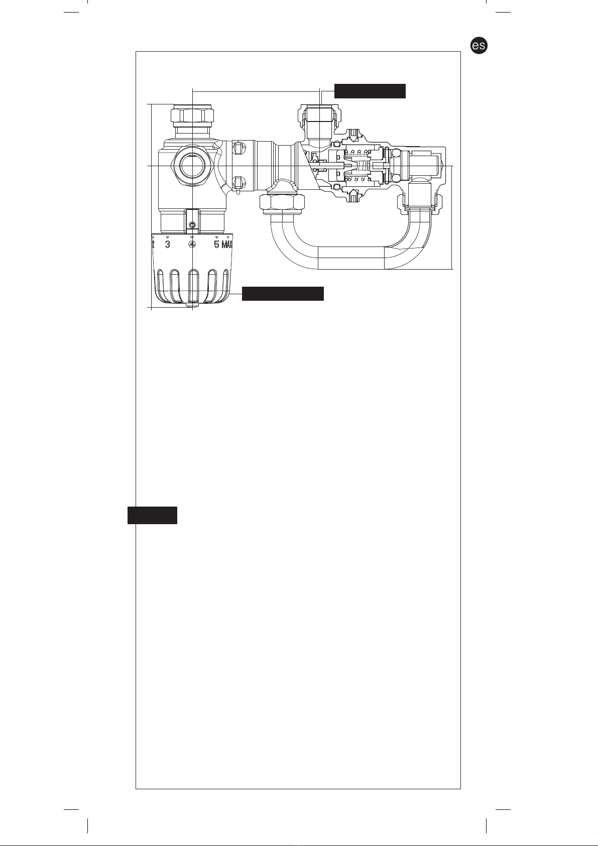
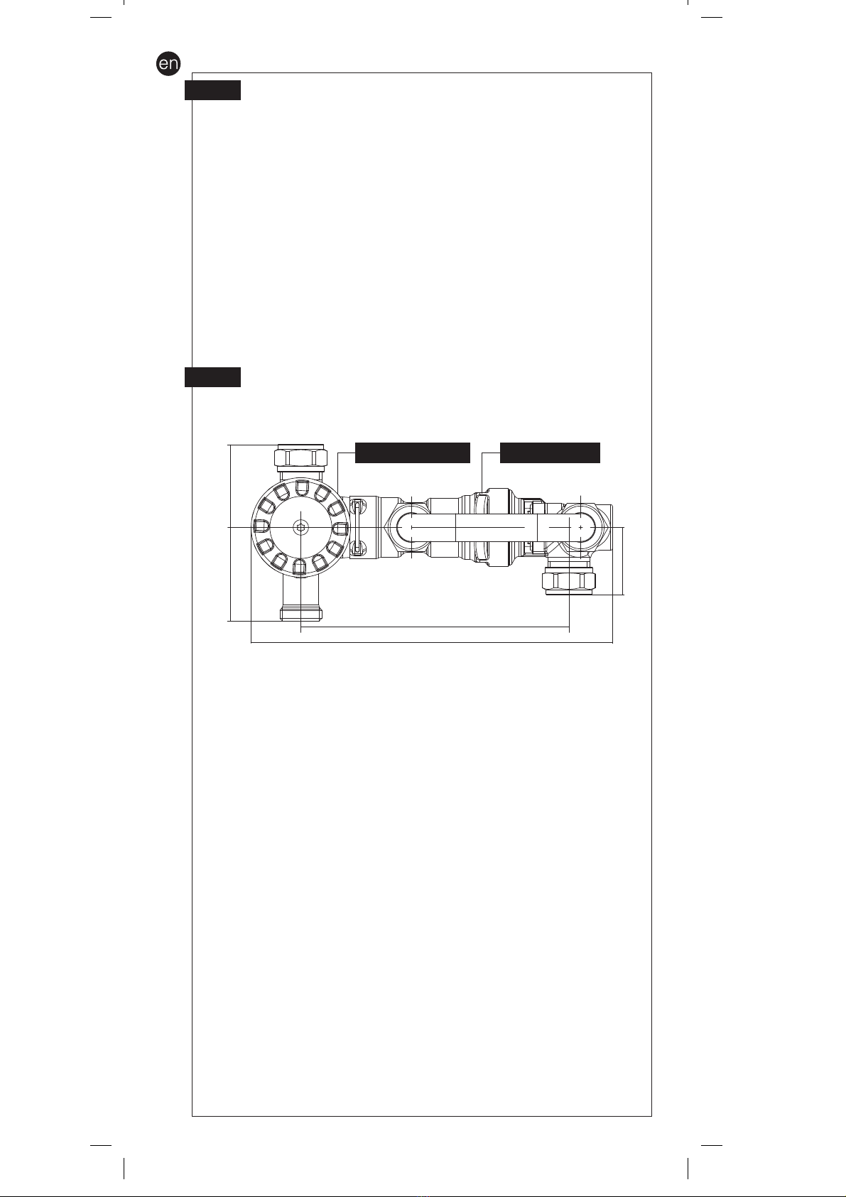
COMPONENTS
1. 3-way valve:
3347
25
135
180
This component is an element that determines whether
the water from the solar storage tank should go
through the supply support or if it can be taken directly
for consumption.
a. If the input temperature is >48ºC, the 3-way valve
bypasses the conventional supply support and takes
the water for consumption directly to the output
mixer.
b. If the input temperature is <48ºC, the valve
deactivates the bypass and makes the water for
consumption circulate through the supply support.
This way, the additional heat source will increase the
temperature of this water as necessary for it to have
sufficient temperature at the sanitary outlet.
This valve is fully watertight and, this way, it prevents
any leakage whatsoever to the support system when
the solar storage tank temperature is higher than the
offset temperature. This prevents having a very high
temperature at the auxiliary equipment’s cold water
inlet.
Mixing valve 3-way valve

64
88 29
79
9
2..JYJOHWBMWF
The mixing valve will adjust the sanitary water outlet
temperature of the solar system + the conventional
support. The hot water supply goes through this
element, whether the flow goes through the support
equipment or not, which ensures a controlled and
stable temperature at the outlet.
Through being able to have temperatures above 55ºC
in the solar storage tank or at the conventional supply
outlet, the mixer will avoid the risk of burns due to
excessively high temperatures.
Mixing valve
3-way valve
3. TECHNICAL SPECIFICATIONS
r 7BMWF NBUFSJBM CSBTT BDDPSEJOH UP UIF &/
standard.
r (BTLFUNBUFSJBM&1%.
r $POOFDUJPOTu./VUCJDPOJDQJQFNN$6PS
flat joint.
r .BYJNVNXPSLJOHUFNQFSBUVSF$
r .BYJNVNXPSLJOHQSFTTVSFCBS
r XBZWBMWFPGGTFUUFNQFSBUVSFDBMJCSBUJPO$
r 0GGTFUUFNQFSBUVSFUPMFSBODF± 2ºC.
r 5IFSNPTUBUJDNJYFSBEKVTUNFOUSBOHF$
r .JYFSPVUMFUUFNQFSBUVSFDBMJCSBUJPO$
r ,WXBZWBMWFN3I
r ,WNJYJOHWBMWFN3I
r $PNQPOFOUTTVJUBCMFGPSVTFXJUITBOJUBSZXBUFS

10
4.
5.
HYDRAULIC SPECIFICATIONS
INSTALLATION
Boiler circuit
Circuit direct to mixer
3500
3000
2500
2000
1500
1000
500
0
0 200 400 600 800 1000 1200 1400 1600 1800 2000 2200
Flow (l/h)
3-way valve PRESSURE DROP
Δ (mbar)
The Solar Sanitary Kit must be installed between the solar
storage tank and the conventional support system. The
solar storage tank’s hot water outlet must be connected
to the inlet of the Solar Sanitary Kit:
The connections of the inlets are shown in the following
diagrams:
Solar storage tank

11
6. GUARANTEE
The Solar Sanitary Kit is guaranteed against all material
faults for 3 years from the manufacturing date marked on
it. This guarantee is not applied if the assembly has been
manipulated, modified or has deteriorated through being
used or installed in a way that does not coincide with the
instructions provided by the manufacturer.
Also,the connection between
the 3-way valve and the
mixer can be turned to make
it easier to install.
Adjustment of output temperature
By modifying the thermostatic mixer’s adjustment point, the
adjustment point of the pre-set temperature of 45ºC can be
modified. The output temperature at the nearest sanitary
outlet must be assured and the temperature within the range
of 30-60ºC must be adjusted to the desired temperature.
Inlet of hot water from the conventional supply
Inlet of cold water from the mains
Hot sanitary water outlet Outlet to the inlet of the cold
water from the conventional
supply
Inlet of water from the solar
storage tank
Inlet of hot water from the
conventional supply (the
same inlet as shown in the
previous diagram)

12
1.
2.
FONCTION
Le "Kit Sanitaire Solaire" est un ensemble pour
raccordement à la source auxiliaire de chauffe pour eau
sanitaire à installer entre l'accumulateur sanitaire solaire
et cette source d'énergie de support : normalement une
chaudière instantanée, un chauffe-eau ou un cumulus
électrique.
Étant donné que l'accumulation sanitaire à énergie solaire n'est
pas stable en température, l'entrée à la source auxiliaire doit
être réglée. C'est pourquoi le "Kit Sanitaire Solaire" doit être
installé à l´entrée de cette source et règle automatiquement un
by-pass et la température de sortie d'eau chaude sanitaire.
PIÈCES
3347
25
135
180
1. Vanne mélangeuse 3 voies :
Cette pièce est un élément qui gère si l'eau provenant de
l'accumulateur solaire doit passer par la source auxiliaire
ou si elle peut être directement acheminée au point de
puissage être consommée.
a. Si la température d'entrée est >48ºC, la vanne 3 voies
fait un by-pass sur la source auxiliaire classique et
achemine l'eau de consommation directement vers
le mélangeur directement vers la sortie de la vanne
mélangeuse.
b. Si la température d'entrée est <48ºC. La vanne désactive
le by-pass et fait circuler l'eau par la source auxiliaire.
De cette manière, la source auxiliaire augmentera la
température de l'eau, qui atteindra alors la température
suffisante pour la consomation d´eau chaude sanitaire.
Cette vanne est complètement étanche pour éviter
toute fuite vers le système auxiliaire lorsque la
température de l'accumulateur solaire est supérieure à
MBUFNQÊSBUVSFEFEÊWJBUJPO/PVTÊWJUPOTBJOTJEhBWPJS
une eau à très haute température à l'entrée d'eau froide
de la source auxiliaire.
Mélangeur Vanne à 3 voies

64
88 29
79
13
2. .ÊMBOHFVS
Le mélangeur règle la température de sortie de
l'eau chaude sanitaire du système solaire+source
de chauffe classique. Que le débit passe ou pas par
a source auxilliaire de support, l'alimentation d'eau
chaude passe par cet élément ; il assure ainsi une
température contrôlée et stable en sortie.
Puisqu'il peut y avoir des températures de plus de
55ºC dans l'accumulateur solaire ou en sortie de la
source de chauffe classique, le mélangeur évite le
risque de brûlures provoquées par de trop fortes
températures.
Mélangeur
Vanne à 3 voies
3. CARACTÉRISTIQUES TECHNIQUES :
r .BUÊSJFMEFTWBOOFTMBJUPOTFMPOMBOPSNF&/
r .BUÊSJFMKPJOUT&1%.
r .BUÊSJFMu.DSPVCJDÔOFUVCFNNDVPV
joint plat.
r 5FNQÊSBUVSFNBYJNBMFEFUSBWBJM90ºC.
r 1SFTTJPONBYJNBMFEFUSBWBJMCBS
r 5BSBHFEFTWBOOFWPJFTUFNQÊSBUVSFEFEÊWJBUJPO
48ºC.
r 5PMÊSBODFUFNQÊSBUVSFEFEÊWJBUJPO ± 2ºC.
r 1MBHF EF SÊHMBHF EV NJUJHFVS UIFSNPTUBUJRVF
30-60ºC.
r 5BSBHFEFUFNQÊSBUVSFFOTPSUJFNJUJHÊF$
r ,WWBOOFÆWPJFTN3I
r ,WNÊMBOHFVSN3I
r $PNQPTBOUTBQUFTQPVSVUJMJTBUJPOQPVS&BV$IBVEF
Sanitaire.

14
4.
5.
CARACTÉRISTIQUES HYDRAULIQUES
INSTALLATION
Circuit chaudière
Circuit direct versmitigeur
3500
3000
2500
2000
1500
1000
500
0
0 200 400 600 800 1000 1200 1400 1600 1800 2000 2200
Débit (l/h)
PERTE DE CHARGE -Vanne 3 voies
Δ (mbar)
LeKitSanitaireSolairedoitêtreinstalléentrel'accumulateur
solaire et le système de chauffe classique. La sortie d'eau
chaude de l'accumulateur solaire doit être connectée
avec l'entrée du Kit Solaire Sanitaire :
-FSBDDPSEFNFOUEFTFOUSÊFTTPSUJFTFTUJOEJRVÊEBOTMFT
schémas suivants :
Accumulateur
solaire

15
6. GARANTIE
Le Kit Sanitaire Solaire est garanti contre tout défaut
de matériel pendant 3 ans à compter de la date de
fabrication marquée sur ce dernier. Cette garantie ne
s'applique pas si l'ensemble a été manipulé, modifié ou
endommagé par une utilisation ou une installation non
conforme aux instructions fournies par le fabricant.
Par ailleurs le raccord entre
la vanne trois voies et le
mitigeur peut être orienté
pour faciliter l'installation.
Réglage de température de sortie
En modifiant le point de réglage du mitigeur
thermostatique il est possible de modifier celui de la
température pré-tarée de 45ºC. Il faut s'assurer de la
température de sortie dans le circuit sanitaire la plus
proche et régler la température sur la plage 30-60ºC à la
température souhaitée.
Entrée d'eau chaude provenant d'une source de chauffe classique
Entrée d'eau froide provenant du réseau
Sortie d'eau chaude sanitaire
Sortie vers l'entrée d'eau
froide de chauffe classique
Entrée d'eau provenant de
l'accumulateur solaire
Entrée d'eau chaude provenant
d'une source classique (même
voie que celle illustrée dans le
schéma précédent)

16
1.
2.
BESCHREIBUNG
Das „Solar Brauchwasser-Anschlussset“ ist eine
Baugruppe zum Verbinden von Warmwasserquellen aus
meist regenerativen Energien und einer Warmwasser-
5IFSNFCFIFJ[UNJU(BT4USPNPEFS¸M
Da die Wärmespeicherung aus regenerativen Energien
keine beständige Temperatur aufweist, muss der Zulauf
in die Therme geregelt werden. Daher wird das „Solar
Brauchwasser-Anschlussset“ am Zulauf in die Therme
eingebaut und regelt so automatisch die Speisung des
Warmwassers und deren Austrittstemperatur.
BESTANDTEILE
1. 3-Wege-Ventil:
3347
25
135
180
Dieses Bauteil entscheidet, ob das Wasser aus dem
Speicher die Therme durchlaufen muss oder direkt
zur Entnahmestelle weitergeleitet wird.
a. Wenn die Eingangstemperatur >48ºC ist, leitet das
3-Wege-Ventil das Wasser an der Therme vorbei
VOEEJSFLU[VN.JTDIWFOUJM#PMM
b. Wenn die Eingangstemperatur <48ºC ist, wird das
Wasser durch die Therme geleitet. Diese Boll erhöht
die Wassertemperatur um den erforderlichen
Wert, damit das Wasser an der Entnahmestelle die
gewünschte Temperatur aufweist.
Das 3-Wege Ventil schließt dicht und verhindert
somit jegliche ungewollte Zufuhr von heißem Wasser
$JOEFO,BMUXBTTFS;VMBVGEFS5IFSNF4PNJU
wird die Therme vor möglichen Schäden geschützt.
Mischventil 3-Wege-Ventil

64
88 29
79
17
2..JTDIWFOUJM
%BT .JTDIWFOUJM SFHVMJFSU EJF "VTHBOHTUFNQFSBUVS
des Warmwassers aus der Solaranlage und der
LPOWFOUJPOFMMFO 5IFSNF 6OBCIÅOHJH EBWPO PC EBT
Wasser durch die Therme fließt oder nicht, erfolgt
EJF 8BSNXBTTFSWFSTPSHVOH EVSDI EBT .JTDIWFOUJM
wodurch eine kontrollierte und gleichbleibende
Austrittstemperatur erzielt wird.
Da sowohl am Solarspeicher als auch am Austritt aus
der Therme Temperaturen von über 55ºC auftreten
LÕOOFO WFSIJOEFSU EBT .JTDIWFOUJM FJO 7FSCSÛIFO
durch zu hohe Temperaturen.
Mischventil
3-Wege-Ventil
3. TECHNISCHE EIGENSCHAFTEN
r .BUFSJBM"SNBUVSFO.FTTJOHHFNÅ/PSN&/
r .BUFSJBM%JDIUVOHFO&1%.
r "OTDIMÛTTF u"( .VUUFS%PQQFMLPOVT $V3PIS
15mm oder Flachdichtung.
r .BYJNBMF"SCFJUTUFNQFSBUVS$
r .BYJNBMFS"SCFJUTESVDLCBS
r &JOTUFMMVOH8FHF7FOUJM6NMFJUUFNQFSBUVS$
r "CXFJDIVOH6NMFJUUFNQFSBUVS± 2ºC.
r 3FHVMJFSVOHTCFSFJDI EFT UIFSNPTUBUJTDIFO
.JTDIWFOUJMT$
r &JOTUFMMVOH"VTUSJUUTUFNQFSBUVS.JTDIWFOUJM$
r ,W8FHF7FOUJMN3I
r ,W.JTDIWFOUJMN3I
r ,PNQPOFOUFO GÛS EFO &JOTBU[ NJU #SBVDIXBTTFS
geeignet.

18
4.
5.
HYDRAULISCHE EIGENSCHAFTEN
EINBAU
Leitung Therme
direkte Leitung zu Mischventil
3500
3000
2500
2000
1500
1000
500
0
0 200 400 600 800 1000 1200 1400 1600 1800 2000 2200
Durchsatz (l/h)
DRUCKVERLUSTE 3-Wege-Ventil
Δ (mbar)
Der Einbau des Solar-Brauchwasser-Anschlusssets muss
zwischen dem Solarspeicher und der Therme erfolgen.
Der Wasseraustritt aus dem Solarspeicher muss mit
dem Eintritt in das Solar-Brauchwasser-Anschlussset
verbunden werden:
Die Verbindung der Anschlüsse wird in den folgenden
Schemazeichnungen dargestellt:
Solarspeicher

19
6. GARANTIE
DasSolar-Brauchwasser-Anschlussset besitzt fürsämtliche
.BUFSJBMGFIMFS FJOF (BSBOUJF WPO +BISFO BC EFN BVG
dem Anschlussset angegebenen Herstellungsdatum.
Diese Garantie erlischt, wenn die Baugruppe infolge von
/JDIUFJOIBMUFO EFS )FSTUFMMFSBOXFJTVOHFO NBOJQVMJFSU
geändert oder beschädigt wurde.
6N EFO &JOCBV [V
vereinfachen, ist das
Verbindungsstück zwischen
3-Wege-Ventil und
.JTDIWFOUJMESFICBS
Einstellung Austrittstemperatur
%VSDI7FSTUFMMFO EFT 3FHFMQVOLUT BN UIFSNPTUBUJTDIFO
.JTDIWFOUJMMÅTTUTJDIEJFWPSFJOHFTUFMMUF5FNQFSBUVSWPO
45ºC ändern. Austrittstemperatur an der nächstliegenden
Brauchwasserentnahmestelle prüfen und Temperatur auf
den gewünschten Wert zwischen 30-60ºC einstellen.
Eintritt Warmwasser aus konventioneller Therme
Eintritt Kaltwasser aus Versorgungsnetz
Austritt Warmwasser für Sanitärzwecke Ausgang zu Kaltwassereintritt
in konventionelle Therme
Eintritt Wasser aus Solarspeicher
Eintritt Warmwasser aus
konventioneller Therme
(gleicher Anschluss wie in
Abbildung oben)

20
1.
2.
&5.+#%
Â3OLfRNq 3ANITfRNq +IT± JE POMOCNm REGULAjNq ZA½ qZENq URjENm
KE STABILIZACI OH½ EVU UË ITKOVm VODY )NSTALUJE SE MEZI SOLfRNq
ZfSOBNqKUË ITKOVmVODYAPODPÒ RNØ ZDROJOH½ EVUUË ITKOVmVODY
4qM JE OBVYKLE KOTEL OH½ qVAj VODY NEBO ELEKTRICKØ ZfSOBNqK
VODY *ELIKOË VØ STUPNq TEPLOTA VODY ZE SOLfRNqHO ZfSOBNqKU
NENq STABILNq MUSq BØ T VSTUPNq TEPLOTA VODY DO PODPÒ RNmHO
ZDROJEREGULOVfNAÂ3OLfRNq3ANITfRNq+IT± SEINSTALUJENAVSTUPU
UË ITKOVm VODY P½ ED PODPÒ RNØ ZDROJ A AUTOMATICKY REGULUJE
VØ STUPNqTEPLOTUUË ITKOVmVODY
+/-0/.%.49
4ROJCESTNØ VENTIL
3347
25
135
180
2OZHODUJEOTOMZDAUË ITKOVfVODAZESOLfRNqHOZfSOBNqKU
PÒ JDE P½ qMO K ODB}RNmMU MqSTU NEBO BUDE DOH½ qVfNA
PODPÒ RNØ MZDROJEM
A 0OKUD JE VSTUPNq TEPLOTA VYÃ Ã q JAK # TROJCESTNØ VENTIL
P½ EPUSTq VODU P½ ES BYPASS P½ qMO DO SM}Ã OVACqHO
VENTILU
B 0OKUD JE VSTUPNq TEPLOTA NIË Ã q JAK # TROJCESTNØ VENTIL
UZAVqRf BYPASS A VODA JE SM}½ OVfNA DO PODPÒ RNmHO
ZDROJEOH½ EVUUË ITKOVmVODY0ODPÒ RNØ ZDROJZVØ Ã qTEPLOTU
UË ITKOVm VODY NA TAKOVOU {ROVEª ABY M}LA DOSTATEjNOU
TEPLOTUNAVØ STUPUZEÂ3OLfRNqHO3ANITfRNqHO+ITU±
4ENTOVENTILJESCHOPNØ PLN}UZAV½ qTVSTUPUË ITKOVmVODYDO
PODPÒ RNmHOZDROJEOH½ EVUUË ITKOVmVODYVP½ qPAD}KDYJE
TEPLOTAVODYVSOLfRNqZfSOBNqKUVYÃ Ã qJAKNASTAVENfTEPLOTA
4qM JE ZABRfN}NO ABY DO PODPÒ RNmHO ZDROJE VSTUPOVALA
VODAOVYSOKmTEPLOT}
3M}Ã OVACqVENTIL 4ROJCESTNØ VENTIL
Table of contents
Languages:
Popular Control Unit manuals by other brands

Rockwell Automation
Rockwell Automation Allen-Bradley Guard master 440F-C4000D user manual

ASCO Valves
ASCO Valves 8210 Series Installation & maintenance instructions

Velocity
Velocity VDOT-ZMU-SCI instruction manual

Johnson Controls
Johnson Controls Tyco RV-1A manual

Arexx
Arexx JM3-GYRO manual

Elk Products
Elk Products ELK-100 manual