10 UM0972031 A 05
User manual
Service menu
Camera- + Minus- and Plus buttons
Service menu
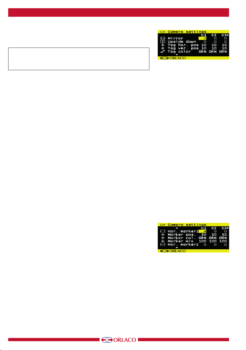
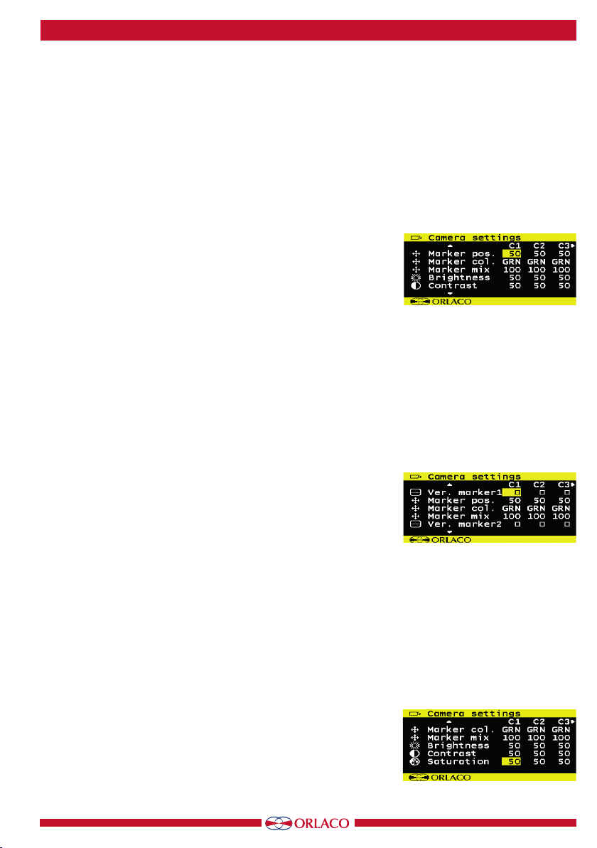
Camera settings
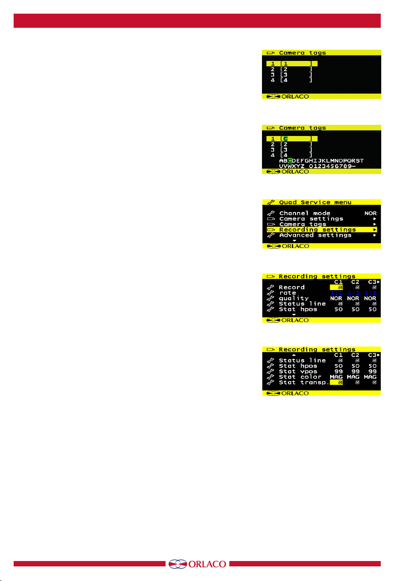
Camera tags
System settings
Info
System settings
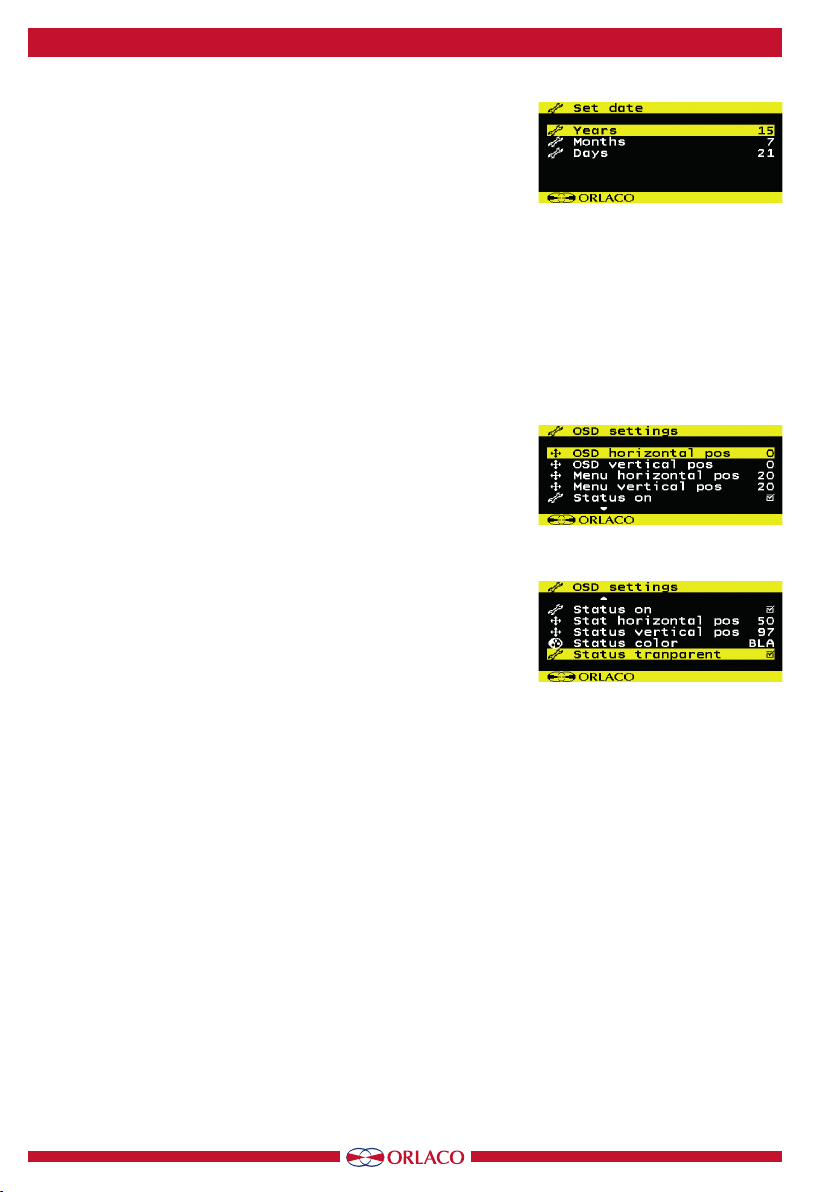
Language
On screen display
Keyboard
Power settings
CAN-bus
LCD-Backlight
Scanning
Camera switch
Frontcam
Default settings
Ext. device config
NOR, ALL, DUA, TRI, REA, D+R, SU1, SU2
Mirror
Upside down
Tag hor. pos
Tag ver. pos
Tag color
Hor marker 1
Marker pos.
Marker col
Marker mix
Hor marker 2
Marker pos.
Marker col
Marker mix
Ver marker 1
Marker pos.
Marker col
Marker mix
Ver marker 2
Marker pos.
Marker col
Marker mix
Brightness
Contrast
Saturation
1, 2, 3, 4
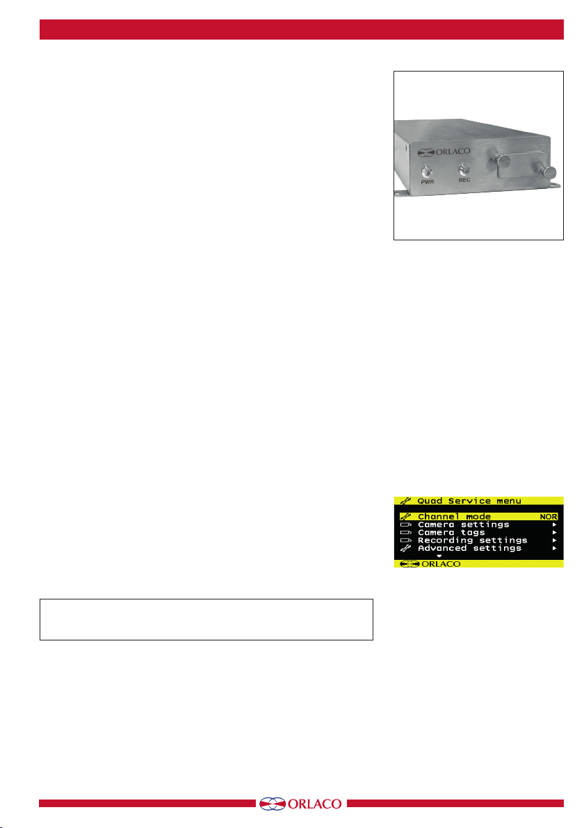
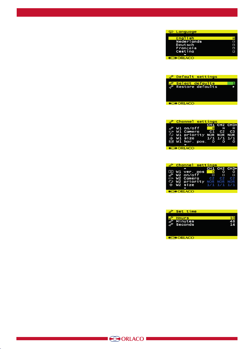
Quad service menu
Channel mode
Camera settings
Camera tags
Recording settings
Advanced settings
info
Set time
Hours
Minutes
Seconds
Default settings
Select defaults
Restore defaults
EN, NL, DE, FR, CS, HU, IT, PL, PO, ES, TR, SV, FI, DA, NO
1:1, 1:2, 1:3, 1:4, 1:5, 1:8, 1:10, 1:15, 1:20, 1:25, 1:30
NOR, LOW, HI
ON/OFF
1, 2, 3
Recording settings
Record
Rate
Quality
Advanced settings
Language
Default settings
Channel settings
Set time
Set date
Set device ID
Format the SD-card
Update firm ware
Switchwire settings
Comm. settings
OSD settings
Boundery settings
W1 on/off, W1 Camera, W1 priority, W1 size, W1 hor. pos,
W1 ver. pos, Mirror, Upside down, W2 ... etc., W3 ... etc., W4 ... etc.
Set date
Years
Months
Days
OSD settings
OSD horizontal pos
OSD vertical pos
Menu horizontal pos
Menu vertcal pos
Status on
Stat horizontal pos
Status vertical pos
Status color
Status transparent
ON/OFF
0 - 100
0 - 100
BLA, BLU, GRN, CYA, RED, MAG, YEL, WHI
ON/OFF
0 - 100
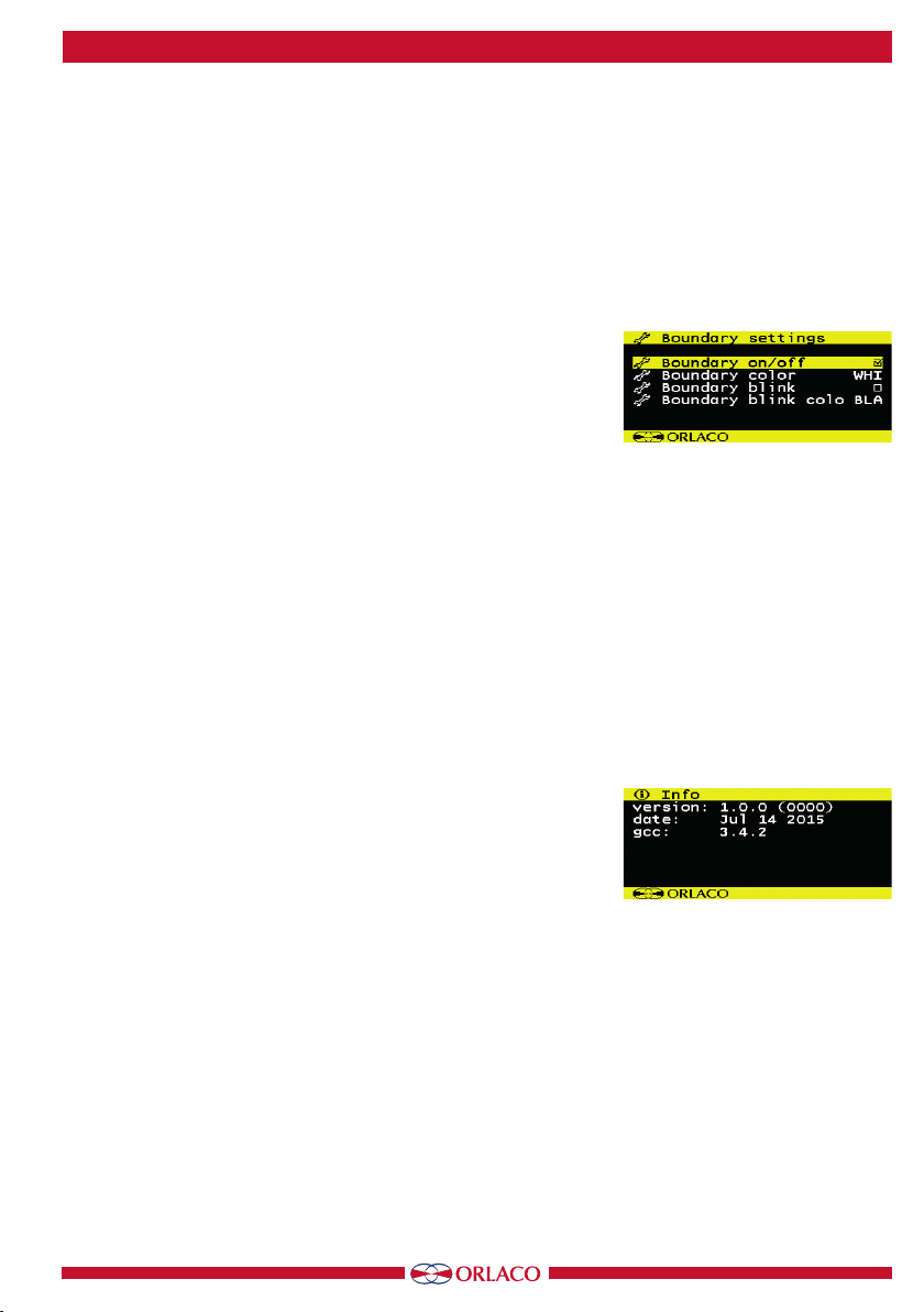
Boundary settings
Boundary on/off
Boundary color
Boundary blink
Boundary blink colo
ON/OFF
ON/OFF
BLA, BLU, GRN, CYA, RED, MAG, YEL,
WHI, G20, G40, G60, G80, UD1, UD2, UD3, UD4
BLA, BLU, GRN, CYA, RED, MAG, YEL,
WHI, G20, G40, G60, G80, UD1, UD2, UD3, UD4
0 - 100
0 - 100
0 - 100
See
User manual
UM0972080
9. Overview of menus