Orlaco Quad box II User manual

Quad box II
Installation Manual
Manual No. IM0973130, A 02
08/2016
English
Article no. 0405300 - 4cam in 1 mon out
0405310 - 1+3 cam in 1 mon out
Article no. 0405300/0405310

2 IM0973130 A 02 IM0973130 A 02 3
Installation Manual Installation Manual
Quad box II
Article no. 0405300- 4cam in 1 mon out
Article no. 0405310- 1+3 cam in 1 mon out
Safety
In order to guarantee safe operation, these safety instruc-
tions must be read before you start using this equipment.
• Do not open the enclosure. The camera and the P&T enclosure are
pressurised. This can cause damage, short-circuiting or electrical
shocks.
• Do not expose the equipment to extreme temperatures. This can cause
deformation of the enclosure or damage to internal components.
• Repairs or adjustments to the equipment may only be undertaken by
Orlaco.
• The equipment must be assembled as shown in this manual.
• If there have been alterations or changes to this equipment that have
not been specifically approved by Orlaco, use of this equipment is not
permitted.
Before you start using this equipment, please read this manual carefully
and follow all instructions. This installation manual describes the func-
tions of the equipment, outlines the connection options and explains how
to put the equipment into operation. We recommend that you keep this
manual in a safe place for reference purposes.
If you have any questions or issues concerning the operation of this
equipment, consult the relevant section in the manual or contact the
Orlaco Products BV Service department.
The camera and monitor systems from Orlaco comply with the latest CE,
ADR, EMC and mirror-directive regulations. All products are manufac-
tured in accordance with the ISO 9001 quality management, ISO/TS16949
quality automotive and ISO 14001 environmental management.
Contens page
1. Description 3
2. System overview 3
2.1. Quadbox II 2 cam in 1 mon out 3
2.2. Quadbox II 1+3 cam in 1 mon out 3
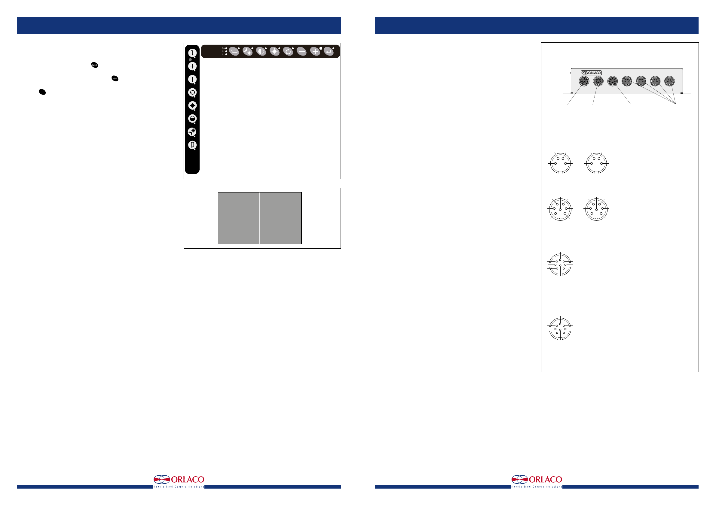
3. Using keyboard display 4
4. Specifications 4
5. Electrical connections 5
6. Dimensions 6
7. Disposal 7
8. General terms and conditions 7
9. Release notes 7
Available documentation
Data sheet DS0963080
Data sheet DS0963081
1. Description
Quad box is is a video system for up to 4 cameras, PAL or NTSC. There
are many possibilities of different split views in 5 selectable video
channels. Advanced video viewing image for various camera-system
configurations.
Software menu
On Screen Display (OSD) functionality for all settings.
Special features
Customizing views, customizing channels, (multi) markers, boundary
settings and camera text labeling
2. System overview
2.1 Quadbox II 4cam in 1 mon out
See figure 1.
2.2 Quadbox II 1 + 3 cam in 1 mon out
See figure 2.
PWR 24Vdc PWR LCD LCD C4 C3 C2 C1
Camera 4
Camera 3
Camera 2
Camera 1
7" RLED Monitor
Quad box II
Art. no 0405300
Power
Red = 24V/DC
White = Ground
Optional
Monitor 12" Serial
Figure 1
Figure 2
Article No. 0405300/0405310
PWR 24Vdc PWR LCD LCD C4 C3 C2 C1
Camera 4
Camera 3
Camera 2
AF-zoom
Camera 1
7" RLED Serial Monitor
Quad box II
Art. no 0405310
Power
Red = 24V/DC
White = Ground
Grey = zoom
Yellow = zoom
Optional
Monitor 12" Serial

4 IM0973130 A 02 IM0973130 A 02 5
objects in
monitor are
closer than
they appear
3. Using keyboard Display
See figure 3.
Off factory the monitor starts up in "Quad Mode". See figure 4.
Using the camera selection button will set the camera selection mode
into "manual mode" (the LED will blink).
In "manual mode" the user can, by using the button, toggle to fulls-
creen camera 1,2,3 and 4 and quad image again.
Using the button the user can toggle backwards.
When the monitor is turned off, the last mode will be saved in memory.
See for full user instructions; Manual UM0972191.
4. Specications
4.1. Article number: 0405300
Housing: Stainless steel AISI 316. The housing is isolated from the
internal electronic parts.
Power input: 24V/DC.
Power LCD: power input
LCD Output monitor: 1x 7pin connector (serial) monitor output.
Camera input: C1-C4: 4x Camera input (4pin connector).
Protection: IP67 according to IEC 60529.
Weight: 1,5kg.
Temperature range: -40°C - +85°C.
Power cable: Included, art. no 8975850: Multi cable 1220900, Connector
8p female Gold 423 1310861. Length = 3,85m
4.2. Article number: 0405310
Housing: Stainless steel AISI 316. The housing is isolated from the
internal electronic parts.
Power input : 18...30V/DC.
Power consumption: 24W @ 24V/DC
Power LCD: Power input
LCD Output monitor: 1x 7pin connector (serial) monitor output.
Camera input: C1: 1x Serial AF Zoom (7pin connector). C2-C4: 3x
Camera input (4pin connector).
Protection: IP67 according to IEC 60529.
Weight: 1,5kg.
Temperature range: -40°C - +85°C.
Power cable: Included, art. no 8975850: Multi cable 1220900, Connector
8p female Gold 423 1310861.
NB: Cameras and monitors are not included.
Nota:
By booting the system may take some time at temperatures below -10°C.
This has to do with the heating time of the cameras.
Camera 1 Camera 2
Camera 3 Camera 4
Keyboard Display 7" RLED
Keyboard Display 12" RLED
5. Electrical connections
5.1. Quad box 4 cam in 1 mon out
See figure 5.
4
1
23
41
2
3
Female
4 pins connector
7 pins connector
8 pins connector
8 pins connector
Male
Female Male
Female
Male
25
74
3
6
1
2
5
7
43
61
6
7
1
3
4
5
2
8
67
13
45
2
8
Power LCD
1 = Red = 24V/DC
2 = White = 0V
3 = Blue = cam 1
4 = Brown = cam 2
5 = White/yellow = cam 3
6 = Grey = cam 4
7 = Yellow = Quad
8 = Not connected
Power Quad box
1 = Red Power 24V/DC
2 = White GND
3 = Blue Cam 1
4 = Brown Cam 2
5 = White/Yellow Cam 3
6 = Grey Cam 4
7 = Yellow Quad
8 = Not connected
Camera 1-4
1 = Coax core video
2 = Coax shield video screen
3 = Red 12V/DC
4 = Black GND
Video LCD
1 = Coax core video
2 = Coax shield screen
3 = Red 15...36V/DC
4 = Black Power ground
5 = Orange Rx
6 = Yellow Tx
7 = Grey Not connected
Installation manual Installation manual
Figure 3
Figure 4
Figure 5
PWR 24Vdc PWR LCD LCD C4 C3 C2 C1
4pins Female
8pins Male
Power Quad box 24V/DC
8pins Female
Power LCD monitor
7pins Male
Video out LCD monitor
camera 1
camera 2
camera 3
camera 4

6 IM0973130 A 02 IM0973130 A 02 7
PWR 24Vdc PWR LCD LCD C4 C3 C2 C1
4pins Female 7pins Female
8pins Male
Power Quad box 24V/DC
8pins Female
Power LCD monitor
7pins Male
Video out LCD monitor
camera 1
camera 2
camera 3
camera 4
Installation ManualInstallation Manual
6. Dimensions
See figure 7.
7. Disposal
Disassembly, removal and disposal. Local regulations for dealing with
waste must be followed when disposing of disassembled components or
entire units.
8. General terms and conditions
Orlaco Products BV is not liable for damage resulting from inadequate
servicing, incorrect usage or alterations made to the equipment without
informing the manufacturer in writing.
This installation manual has been made available by Orlaco Products
BV. All rights reserved. No part of this manual may be reproduced and/
or made public in printed form, in photocopy form or on microfilm, or in
any other way, without the prior written permission of Orlaco. This also
applies to the associated drawings and figures.
Orlaco reserves the right to make changes to components at any time
without informing customers beforehand or directly. All dimensions given
are for commercial purposes.
For information regarding repairs that is not covered in this manual,
please contact the Orlaco Products BV service department.
This manual has been prepared with all due care and attention. However,
Orlaco Products BV cannot be held responsible for any errors in this
manual or any consequences thereof.
FCC compliance statement:
The camera comes under section for commodity codes for electronic
equipment. This is known as “Harmonize code: 8525.30.9060” and the
importer can check off Block 2 on FCC form which states: “An FCC grant
of equipment authorization and an FCC ID are not required, but the equip-
ment complies with FCC technical requirements.”
Caution: Any changes or modifications in the construction of this device
which are not expressly approved by the party responsible for compliance
could void the user’s authority to operate the equipment. Camera/Display
sets are visual aids and objects visible in camera/Display systems are
smaller or bigger than they appear on screen.
9. Release Notes
A01. New edition, 8/2016.
A02. Art. no. 0405310 added, 4/2017.
5.2. Quad box 1 + 3 cam in 1 mon out
See figure 6.
240
105
220
120
50
∅5 4x
PWR 24Vdc PWR LCD LCD C4 C3 C2 C1
Protective caps
Multi cable
Art. no 1220900
240
105
220
120
50
∅5 4x
PWR 24Vdc PWR LCD LCD C4 C3 C2 C1
Protective caps
Multi cable
Art. no 1220900
Figure 7
4
1
23
41
2
3
Female
4 pins connector
7 pins connector
8 pins connector
8 pins connector
Male
Female Male
Female
Male
25
74
3
6
1
2
5
7
43
61
6
7
1
3
4
5
2
8
67
13
45
2
8
Power LCD
1 = Red = 24V/DC
2 = White = 0V
3 = Blue = cam 1
4 = Brown = cam 2
5 = White/yellow = cam 3
6 = Grey = cam 4
7 = Yellow = Quad
8 = Not connected
Power Quad box
1 = Red Power 24V/DC
2 = White GND
3 = Blue Cam 1
4 = Brown Cam 2
5 = White/Yellow Cam 3
6 = Grey Cam 4
7 = Yellow Quad
8 = Not connected
Camera 2-4
1 = Coax core video
2 = Coax shield video screen
3 = Red 12V/DC
4 = Black GND
Video LCD
1 = Coax core video
2 = Coax shield screen
3 = Red 15...36V/DC
4 = Black Power ground
5 = Orange Rx
6 = Yellow Tx
7 = Grey Not connected
Camera 1
1 = Coax core video
2 = Coax shield screen
3 = Red 12/24V/DC
4 = Black Power ground
5 = Orange Rx
6 = Yellow Tx
7 = Grey Not connected
Figure 6
4
1
23
41
2
3
Female
4 pins connector
7 pins connector
8 pins connector
8 pins connector
Male
Female
Male
Female
Male
25
74
3
6
1
2
5
7
43
61
6
7
1
3
4
5
2
8
67
13
45
2
8

www.orlaco.com
Orlaco is a Manufacturing company that specializes in making cameras
and monitor systems for commercial vehicles, fork-lift trucks, cranes, off
shore and maritime.
Our objective is to design and produce camera systems for the profes-
sional market that improve the drivers view and increase operating
efficiency.
At our factory in Barneveld, we have a production department, ware-
house, design department, service department and showroom.
Vision is our mission®, and Orlaco therefore deploys the development,
manufacture, supply and service of camera and display systems that will
improve safety and efficiency of all vehicles, machinery and vessels. Our
systems give the end user a view on each blind spot and create comfort
and improved working conditions. Our active approach will support mar-
ket demands and innovations and will lead to enthusiastic ambassadors
in the market; our Customers.
For more information: www.orlaco.com
ORLACO
This manual suits for next models
2
Table of contents
Other Orlaco Recording Equipment manuals
Popular Recording Equipment manuals by other brands

Roland
Roland CSQ-600 owner's manual

Olympus
Olympus T1010 - Pearlcorder Transcriber Transcription Machine... instruction manual

Emcotec
Emcotec RC Electronic DPSI RV operating instructions

NETmc Marine
NETmc Marine DVR user guide

DAF
DAF DAVIE XDc II Quick start manual

TC Electronic
TC Electronic DVR250 NATIVE user manual