Orolia GXClok-500 User manual

19 December 2022
GXClok-500
Auto-Adaptive GPS/GNSS Receiver and Crystal
Oscillator Module
User Manual
Document Part No: GXClok-500_Manual
Revision: 191222

Contents
1. Introduction............................................................................................................................................................................................................4
2. System description.............................................................................................................................................................................................4
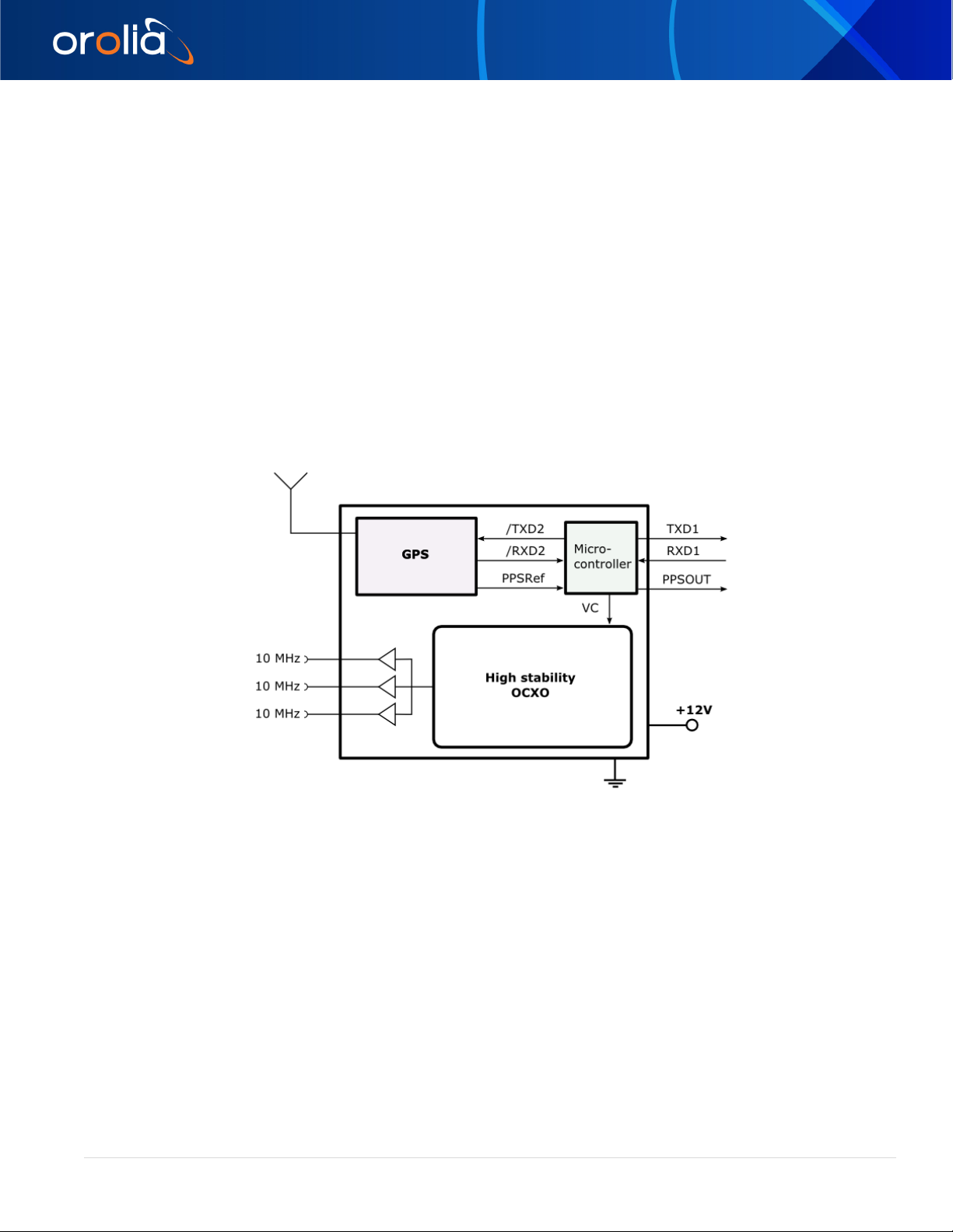
2.1 Block diagram.............................................................................................................................................................................................4
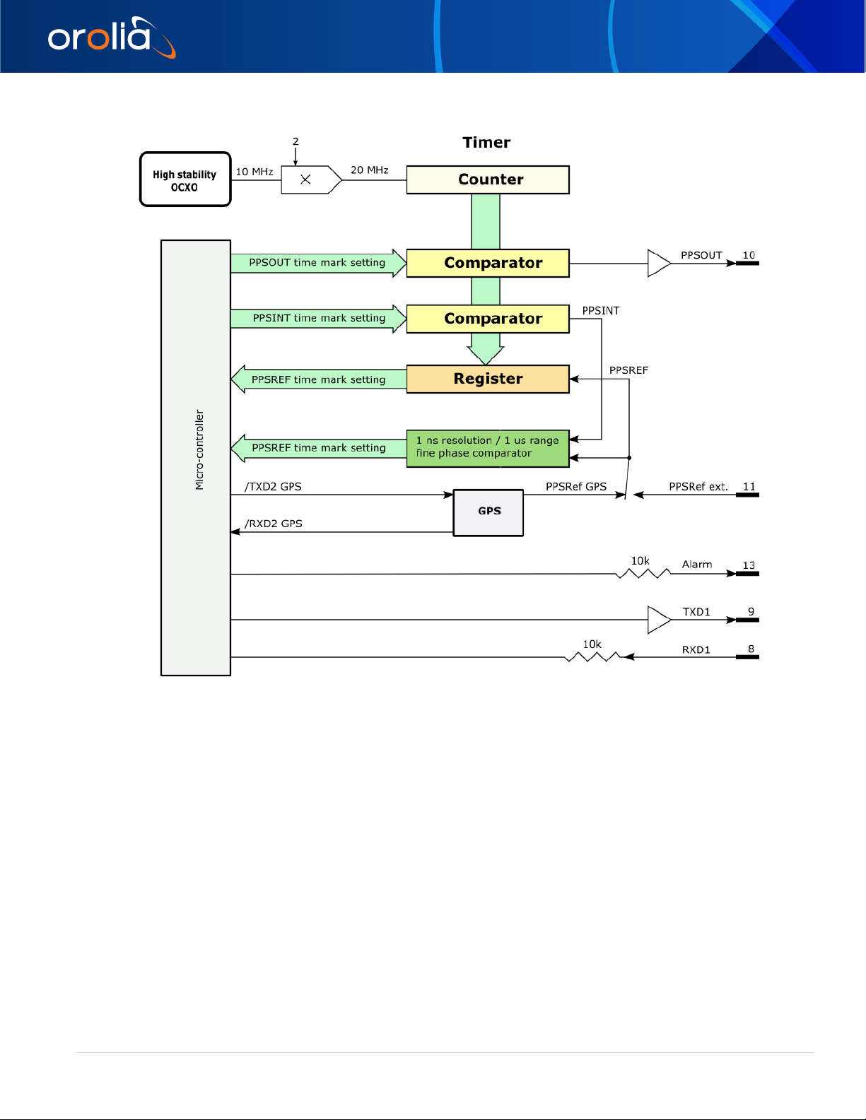
2.2 THE TIMING AND TRACKING SYSTEM OF THE GXCLOCK .............................................................................................. 5
2.2.1 THE “TRACK” MODE AND THE “SYNC” MODE..................................................................................................... 6
2.2.2 THE FREQUENCY LEARNING ........................................................................................................................................ 6
2.2.3 THE FREQUENCY IN USE................................................................................................................................................. 6
2.2.4 USER FREQUENCY CORRECTION.............................................................................................................................. 7
2.2.5 THE PPS TRACKING LOOP ............................................................................................................................................. 7
2.2.6 TRACKING LIMITS AND ALARMS................................................................................................................................. 7
2.2.7 FREQUENCY FLUCTUATIONS DURING THE TRACKING................................................................................8
2.2.8 FINE PHASE COMPARATOR OFFSET....................................................................................................................... 8
2.2.9 THE AUTOMatical RESTART OF THE TRACKING................................................................................................ 8
3. GXClock INSTALLATION AND OPERATION.........................................................................................................................................9
3.1 INTRODUCTION .......................................................................................................................................................................................9
3.2 Safety! ............................................................................................................................................................................................................9
3.3 Environmental Responsibility.............................................................................................................................................................. 9
3.4 SHIPPING AND RECEIVING INFORMATION...............................................................................................................................9
3.5 MOUNTING................................................................................................................................................................................................ 10
3.5.1 RF jamming of the GPS .................................................................................................................................................... 10
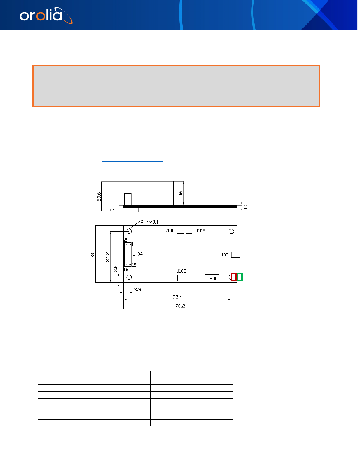
3.5.2 GXClock-500 PACKAGE................................................................................................................................................. 10
3.5.3 PIN OUT ................................................................................................................................................................................... 10
3.6 SIMPLE SERIAL INTERFACE OPERATION................................................................................................................................11
3.6.1 INTRODUCTION....................................................................................................................................................................11
3.6.2 SERIAL INTERFACE CONNECTION ...........................................................................................................................11
3.6.3 GXClock INTERNAL PARAMETERS MONITORING.............................................................................................11
3.6.4 CENTRE FREQUENCY ADJUSTMENT WITH THE SERIAL INTERFACE ................................................12
3.6.5 CENTER FREQUENCY READ-BACK......................................................................................................................... 12
3.7 Status & Alarms....................................................................................................................................................................................... 12
4. Timing & Locking Control Functions extended list...........................................................................................................................13
4.1 INFORMATION COMMANDS ...........................................................................................................................................................13
4.2 TRACKING COMMANDS .................................................................................................................................................................... 13
4.3 PPSOUT COMMANDS......................................................................................................................................................................... 13
4.4 DATE / TIME COMMANDS................................................................................................................................................................14
4.5 SETTING COMMANDS ........................................................................................................................................................................14
4.6 OTHER COMMANDS............................................................................................................................................................................14
4.7 DEVICE STATUS.................................................................................................................................................................................... 42
4.7.1 STATUS BROADCASTED BY MESSAGES............................................................................................................. 42
4.8 THE MAvxx.. SYSTEM.......................................................................................................................................................................... 42
4.8.1 INTRODUCTION.................................................................................................................................................................. 42
4.9 MAVxx.. PARAMETERS DESCRIPTION FOR THE GXClock.............................................................................................44
4.9.1 Clock main parameters .................................................................................................................................................... 44
4.9.2 GPS main parameters....................................................................................................................................................... 44
4.10 SERIAL COMMUNICATION INTERFACE 2...............................................................................................................................69
4.11 The NMEA messages........................................................................................................................................................................... 70

4.11.1 Conditions : ............................................................................................................................................................................ 70
4.11.2 Messages activation:.......................................................................................................................................................... 70
4.11.3 Messages cancellation: ..................................................................................................................................................... 70
4.11.4 The NMEA messages list:................................................................................................................................................ 70
4.11.5 Message NMEA $PTNTA.................................................................................................................................................. 71
4.11.6 Message NMEA $PTNTS,B.............................................................................................................................................. 71
4.11.7 Message NMEA $GPRMC ............................................................................................................................................... 72
4.11.8 Message NMEA $GPZDA ................................................................................................................................................ 73
4.12 THE NMEA $GPRMC mode .............................................................................................................................................................. 74
4.13 Special commands ................................................................................................................................................................................ 75
4.14 Time of Day Command Synchronization.................................................................................................................................... 75
4.15 Time tagging on the PPSREF input and the BT8 command............................................................................................ 76
4.16 Signification of the BT9 message.................................................................................................................................................. 76
4.17 Time and date in use in the iSync clock ...................................................................................................................................... 77
4.18 The time constant of the PI loop, GXClock............................................................................................................................... 77
4.19 GXClock simplified state machine and Status indication ................................................................................................... 78
5. Annexes................................................................................................................................................................................................................. 79
5.1 Typical tunings ........................................................................................................................................................................................ 79
5.1.1 Start of a tracking............................................................................................................................................................... 79
5.1.2 Automatic start of the tracking.................................................................................................................................... 80
5.1.3 Low Time Interval Error with the PPSRef from the GPS.................................................................................81
5.1.4 Very good short term frequency stability ............................................................................................................... 82
5.1.5 Improved holdover performance ................................................................................................................................ 82
5.1.6 Tracking an external PPSREF....................................................................................................................................... 82
5.1.7 Direct communication with the GPS receiver....................................................................................................... 83
5.1.8 Testing the GPS jamming ............................................................................................................................................... 84
Revisions List
Software Revision (based on GXCLOCK-500 standard SW):
Hardware Revision :
Date
Version
Prompt / ID
Comment
2012-11-08
2.10
SPTSXO-002/00/2.10 2012-11-08
2012-12-10
2.10
SPTSXO-002/00/2.10 2012-12-10
Minor sw changes
2013-12-02
2.10
SPTSXO-002/00/2.10 2013-12-02
Command FC possibly don't write in eeprom
2014-05-13
2.10
SPTSXO-002/00/2.10 2014-05-13
TR1, SY1, warming delay of 320 seconds:
settled by default
2017-06-19
2.10
SPTSXO-002/00/2.10 2017-06-19
Minor sw changes

orolia.com GXClok-500 Manual | 4
clocksupport@orolia.com Orolia Switzerland +41.32.732.16.66
GXClok-500 User Manual
1. Introduction
The GXClock-500 is a high-performance crystal oscillator locked on a timing GPS receiver. Based on a technology
developed for Rb Clocks, it has exceptional performance in frequency spectral purity, timing and holdover capability.
The GXClock-500 is a secure and synchronized time source for terrestrial communication systems.
2. System description
2.1 Block diagram
Figure 3-1 Building block of the GXClock-500

orolia.com GXClok-500 Manual | 5
clocksupport@orolia.com Orolia Switzerland +41.32.732.16.66
GXClok-500 User Manual
2.2 THE TIMING AND TRACKING SYSTEM OF THE GXCLOCK
Figure 3-2 Timing system.
This iSync includes extended PPS (Pulse Per Second) facility. The hardware of this facility consists of two modules. The
first module is a timer clocked at 20 MHz. This timer tags the PPSREF coming from the internal GPS or from the outside,
pin 11, and generates two other PPS. The first one is called PPSINT and is used internally. The second one is called
PPSOUT and appears on pin 10 of the connector.
The second module is a phase comparator with 1 ns resolution and 1 µs range. This module compares the phase between
PPSREF and PPSINT. The phase information is used for the perfect tracking of a low noise PPSREF and for calculating
the noise of this PPSREF. The calculation is used to adjust the time constant of the tracking loop. This way, a noisy
PPSREF can be directly connected to the device without adjustments by hard or software.

orolia.com GXClok-500 Manual | 6
clocksupport@orolia.com Orolia Switzerland +41.32.732.16.66
GXClok-500 User Manual
2.2.1 THE “TRACK” MODE AND THE “SYNC” MODE.
Figure 3-3 "Track" mode and "Sync" mode.
When “track” mode is set-up, the PPSINT is aligned to the PPSREF within 50 ns and the device start to track it. At the
beginning the loop time constant is set to an arbitrary low value. Then the phase comparator starts the long-term
frequency stability analysis of the PPSREF and the loop time constant is set accordingly.
If “sync” mode is not active, the PPSOUT is let in the place where it was before going in tracking.
If “sync” mode is active, the PPSOUT is aligned to PPSINT, just after going in tracking if it was set already or just after it is
set elsewhere.
Remark: Just after the beginning of tracking, PPSINT is not perfectly aligned to PPSREF. The error can be as big as 50
ns. Of course, the tracking loop will cancel this error after some time.
2.2.2 THE FREQUENCY LEARNING
When the GXClock is tracking the PPSREF of the GPS, in reality, it aligns its frequency to the one of the GPS system.
The learning process is simply the memorization of this frequency from time to time to use it after a reset or Power-On.
By default, when the device is continuously and successfully tracking a PPSREF, the average value of the frequency is
saved in EEPROM every 24 hours.
With the command FSx, it is possible to cancel the learning or to make an immediate save.
2.2.3 THE FREQUENCY IN USE
With the PPSREF facilities, a different frequency can be in use in different situations. Let know first, that the frequency
just currently in use is located in a single register, and that this register can ever be read by the user. The command to
read this register is: FC??????.
On a device connected through the serial interface to a terminal, it is possible to follow the evolution of the tracking by
this way. The frequency in use in different situations is as follows:
•After a Reset or Power-On, the value is copied from the EEPROM to the RAM and is used.
•When not in tracking, the command FCsddddd or the command Cxxxx, change the value in use and store it in the
EEPROM.
•At the beginning of a tracking, the value in use is the one of the EEPROM.
•During a tracking, the value in use changes continuously to align the PPSINT to the PPSREF. A holdover frequency is
also estimated continuously. By default, the holdover frequency is saved in EEPROM every 24 hours.
•When the tracking is stopped intentionally, the device goes in FREE RUN and the value in EEPROM becomes in use.
•If a tracking is stopped because of a degraded or a missing PPSREF, the iSync goes in HOLDOVER with the holdover
frequency previously estimated.

orolia.com GXClok-500 Manual | 7
clocksupport@orolia.com Orolia Switzerland +41.32.732.16.66
GXClok-500 User Manual
2.2.4 USER FREQUENCY CORRECTION
This correction is only possible in Free Run mode and is made with the command FCsddddd.
The command has 2 effects:
-Memorization of the asked frequency in EEPROM.
-Immediate use of the new frequency.
2.2.5 THE PPS TRACKING LOOP
The iSync is equipped with a numerical PI regulation loop to track the PPSREF. The time constant of the tracking loop is
either set automatically, or forced by the user with the command TCdddddd.
e
PPSINT
PPSREF
U
Osc
K
∫
dt
PI
regulator
Figure 3-4 Schematic of the PPSREF regulation loop.
By default the time constant is set automatically. In such situation, the optimum loop time constant is computed from
information’s like PPSREF noise and temperature fluctuations. If this information is missing, the time constant is slowly
forced to 1000 second in the GXClock.
2.2.6 TRACKING LIMITS AND ALARMS
If the frequency between the iSync and the master to track is too large, after some time, the phase time error between
PPSINT and PPSREF can become too big for some applications.
There are two limits. If the phase time error becomes bigger than the first limit, an alarm is raised up, but the tracking
continues. If the phase time error comes bigger than the second limit, then the tracking stops. The first limit is called (no)
alarm window and the second window tracking window. The value of the half (no) alarm window can be changed by the
user with the command AWddd. For the GXClock, the default value is ± 20µs. The value of the half tracking window can
be changed by the user with the command TWddd. For the GXClock, the default value is ± 60µs. For more details, see
the Chapter “TIMING AND TRACKING COMMANDS”.
Figure 3-5 Tracking limits.

orolia.com GXClok-500 Manual | 8
clocksupport@orolia.com Orolia Switzerland +41.32.732.16.66
GXClok-500 User Manual
2.2.7 FREQUENCY FLUCTUATIONS DURING THE TRACKING
By default, during a tracking, the GXClock is able to tune it's frequency on the nearly full range given by a 16
bit number. In reality from FC-32765 to FC+32765. Or in relative frequency: > ±4e-7.
In case the frequency limit is reached during a tracking, no error will be raised up as long the phase time error is staying
in the (no) alarm window.
So high frequency variations are may be not acceptable in some applications. In such case it is possible to lower the limit
by software tuning, See MAv.. parameters, Frequency limit.
2.2.8 FINE PHASE COMPARATOR OFFSET
This fine offset adjustment can be used in case of precise phase calibration. The range of the offset is +127/ - 128 steps
of the fine phase comparator. As the fine comparator works analogue, a step corresponds to approx. 1 ns. The
command to put the offset is COsddd
Figure 3-6 schematic of the analog fine phase comparator regulation loop
2.2.9 THE AUTOMatical RESTART OF THE TRACKING
In a situation where just a frequency disciplining is asked, like in a laboratory, it is recommended to allow the automatically
restart of the tracking by setting MAv parameter 0x06, bit 2 to 1.
In other situations, like synchronization of a base station to the GPS constellation, it is recommended to not allow this
automatically restart by setting MAv parameter 0x06, bit 2 to 0. This way GPS receiver anomaly may be cancelled. But this
induce stacking in Status=5 problem. To fix up this, it is recommended to restart the tracking (local controller).

orolia.com GXClok-500 Manual | 9
clocksupport@orolia.com Orolia Switzerland +41.32.732.16.66
GXClok-500 User Manual
3.GXClock INSTALLATION AND OPERATION
3.1 INTRODUCTION
This chapter of the manual contains information regarding the installation and operation of the SpT Model GXClock. It is
recommended to read this chapter carefully prior to operate the unit.
3.2 Safety!
- Use proper ESD precautions
- Ensure that all cables are properly connected
Handling the product in a reasonably foreseeable conditions do not cause any risk for human health, exposure to the
SVHC (substances of very high concern) would require grinding the component up.
3.3 Environmental Responsibility
•The equipment contains materials, which can be either re-used or recycled.
•Do not deposit the equipment as unsorted municipal waste. Leave it at an authorized local WEEE collection point or
return to Orolia Switzerland SA to ensure proper disposal.
•To return the appliance :
a. Download and fill up the RMA form (from orolia.com) and send it to clocksupport@orolia.com
b. Once the RMA is approved, we will contact you with shipment process details.
3.4 SHIPPING AND RECEIVING INFORMATION
The GXClock is packaged and shipped in a foam-lined box. The unit is inspected mechanically and electrically prior to
shipment. Upon receipt of the unit, a thorough inspection should be made to ensure that no damage has occurred during
shipping. If any damage is discovered, please contact
OROLIA SWITZERLAND SA
PHONE: +41 32 732 16 66
FAX: +41 32 732 16 67
CH-2000 NEUCHATEL / SWITZERLAND
Should it be necessary to ship the unit back, the original case and packing should be used. If the original case is not
available, a suitable container with foam-packing is recommended.
CAUTION
Care must be taken for the transportation of the GXClock to ensure that the maximum acceleration due to a choc
50g/ 18ms is not exceeded. GXClock contains crystal resonator.
When GXClock is integrated into an instrument, such instrument shall be packed in a suitable container, similar to
containers generally used for the transportation of instruments like scope, video display or computer.

orolia.com GXClok-500 Manual | 10
clocksupport@orolia.com Orolia Switzerland +41.32.732.16.66
GXClok-500 User Manual
3.5 MOUNTING
The unit should be mounted in preference to a metallic base-plate or thermal dissipater.
CAUTION
Care must be taken to ensure that the maximum operating temperature is not exceeded. (+/0°C as measured upper
the OCXO).
This maximum temperature can be reached when operating the unit into forced air flow. Vertical mounting is
preferred to improve cooling by air connection around the OCXO.
The device is designed for being directly mounted on the host instrument PCB. The device mounting depends on the
available space and the ambient temperature into the instrument.
3.5.1 RF jamming of the GPS
The GXClock-500 is hosting a GPS receiver that is sensitive to RF jamming, especially near 1575 MHz. Avoid to place the
GXClock-500 nearby RF emitting devices. If jamming is suspected, it is possible to measure it with indications given in
"Typical Tunings" Chapter: Testing the GPS jamming.
3.5.2 GXClock-500 PACKAGE.
J100: GPS antenna MMCX in the PCB plane
J101: 10MHz output MMCX straight
J102: 10MHz output MMCX straight
J103: 10MHz output MMCX straight
J104: INTERFACE Hirose DF11-16DP-2DSA01
3.5.3 PIN OUT
J104
1
+10MHz LVDS
2
-10MHz LVDS
3
10MHz TTL
4
-1PPS LVDS
5
+1PPS LVDS
6
GND
7
Device OK 0-3V +5k
8
RX 232
9
TX RS232 (0-5V)
10
PPS TTL
11
1PPSIN C-MOS
12
GND
13
Alarm Track/Sync 0-3V +5k
14
GND
15
+12V
16
+12V
D200
D201

orolia.com GXClok-500 Manual | 11
clocksupport@orolia.com Orolia Switzerland +41.32.732.16.66
GXClok-500 User Manual
3.6 SIMPLE SERIAL INTERFACE OPERATION
3.6.1 INTRODUCTION
The GXClock is equipped with a micro-controller which supervises the normal working of the device. All the working
parameters are stored in a built-in EEPROM memory.
The built-in serial interface allows an automatic parameter adjustment during the manufacturing.
The serial interface serves also for the monitoring and tuning of the internal parameters and the PPS facilities.
3.6.2 SERIAL INTERFACE CONNECTION
The data transfer from the GXClock can be made by direct connection to a PC or standard terminal.
The data transfer parameters are the following:
bit rate: 9600 bits/s.
parity: none
start bit: 1
data bits: 8
stop bit: 1
IMPORTANT NOTE:
In most cases, the serial PC interface accepts the 0 to 5V level and a direct connection can be made. In case this 0 to
5V standard is not working, please refer to the small adaptation circuit called ‘RS 232 adapter circuit’
described in annex I.
If you experience problems with the serial interface, have a look into the FAQ section of the www.spectratime.com web
site.
3.6.3 GXClock INTERNAL PARAMETERS MONITORING
The internal parameters monitoring is made via the serial interface and with the use of single command "M" followed by
a carriage return character.
M<CR>[<LF>]
The GXClock will respond to this single character command with an eight ASCII / HEX coded string which looks like:
HH GG FF EE DD CC BB AA <CR><LF>
Where each returned byte is an ASCII coded hexadecimal value separated by a <Space> character.
The values are indicative and not scaled.
HH:
reserved
GG
: PCB temperature
FF
: reserved
EE
: reserved
DD
: OCXO Voltage Control
CC
: reserved
BB
: reserved
AA
: reserved
PCB temperature [Celsius] = 0xGG * 0.5859 - 10.0

orolia.com GXClok-500 Manual | 12
clocksupport@orolia.com Orolia Switzerland +41.32.732.16.66
GXClok-500 User Manual
3.6.4 CENTRE FREQUENCY ADJUSTMENT WITH THE SERIAL INTERFACE
A single character command is available to the user for center frequency adjustment.
Cxxxx <CR>[<LF>] : output frequency correction through the synthesizer, by steps of approx. 6·10-12, where xxxx is
a signed 16 bits integer in hexadecimal string representation.
This value is stored in an EEPROM as last frequency correction which is applied after RESET or power-ON operation.
* Warning : This command can act into non volatile memory. Numbers of commands sent during the whole unit life time
limited to 100'000 in total (all commands cumulated). See MAv06: 4 parameter to cancel the eeprom writing. (Since
Version 2013-12-02)
•The argument of this command can vary from 0x8000 to 0x7FFF (-32768 to 32767).
•In track state, the frequency is changed internally by the software for optimum alignment and this command is no
more active.
•The basic command FCsddddd does the same.
•Even if MAv06:4 parameter is settled to cancel the writing in eeprom of FC, a writing in eeprom is anyway possible if
the command FCsddddd is followed by the command FS3
Examples:
C0000<CR>
: return to the nominal value (factory setting).
C0010<CR>
: the actual frequency is increased of 16 steps.
CFFF0<CR>
:the actual frequency is decreased of 16 steps.
3.6.5 CENTER FREQUENCY READ-BACK
R05<CR>[LF] : read-back high byte of user frequency correction actually in use.
R06<CR>[LF] : read-back low byte of user frequency correction actually in use.
L05<CR>[LF] : read-back high byte of user frequency correction in use after RESET or power-ON.
L06<CR>[LF] : read-back low byte of user frequency correction in use after RESET or power-ON.
-In track state, the value of these registers is subject to be changed by the software for optimum alignment.
3.7 Status & Alarms
Status Device ok
Alarm
Track Mode
Sync Mode
Pin 7
LED Green
Pin 13
LED red
Pin 13
LED red
S=0 warming up
(Low)(4)
(OFF)(4)
High
ON
High
ON
S=1 tracking set-up
High
ON
High
ON
High
ON
S=2 track to GPS (PPSREF)
High
ON
Low
OFF
N/A
N/A
S=3 Sync to GPS (PPSREF)
High
ON
N/A
N/A
Low
OFF
S=4 FreeRun. Track OFF
High
ON
High
ON
High
ON
S=5 HO(1) PPSREF unstable
High
ON
High
ON
High
ON
S=6(3) HO(2) No PPSREF
High
ON
High
ON
High
ON
S=7 Factory used
High
ON
High
ON
High
ON
(1) HO means Hold Over. Device still in Free Run if PPSREF unstable during tracking set-up
(2) HO means Hold Over : Device still in Free Run if No PPSREF during tracking set-up
(3) Status =6 also if GPS message activated (MAv22: Bit0:1) AND missing or defective GPS messages
Remarks: It is possible to deactivate “Device OK” and “Alarm” by SW, (MAv04:Bit6:1) In such case, pins 7,13 are Low
and LED’s OFF

orolia.com GXClok-500 Manual | 13
clocksupport@orolia.com Orolia Switzerland +41.32.732.16.66
GXClok-500 User Manual
4. Timing & Locking Control Functions extended list
Extended commands beginning with 2 characters are implemented in the device for efficient managing, setting, tuning,
reading back and surveying. Like the 1 character commands, this commands use the serial port 1.
4.1 INFORMATION COMMANDS
ID
Identification.
SN
Serial number.
ST
General Status.
BTx
Beat a message (every second) on the serial port.
VS
View PPSRef Sigma.
VT
View Time constant.
4.2 TRACKING COMMANDS
TRx
Tracking start and stop.
SYx
PPSOUT synchronization.
AWddd
Set the no alarm window during a tracking.
TWddd
Set the tracking window during a tracking.
TCdddddd
Set tracking loop time constant.
FSx
Set frequency saving.
COsddd
Set phase comparator Offset.
RAsddd
Raw phase adjust.
4.3 PPSOUT COMMANDS
PWddddddddd
Set the PPSOUT pulse width.
DEddddddddd
PPSOUT delay.
PPdddeee
Set PPSOUT cadence and initial phase.

orolia.com GXClok-500 Manual | 14
clocksupport@orolia.com Orolia Switzerland +41.32.732.16.66
GXClok-500 User Manual
4.4 DATE / TIME COMMANDS
DT
Send out the date.
DTyyyy-mm-dd
Set the date.
TD
Send out the time of day.
TDhh:mm:ss
Set the time of day.
4.5 SETTING COMMANDS
FCsddddd
Change frequency.
MAvxx..
Module adjust. Set and read internal parameters.
4.6 OTHER COMMANDS
FREEZEx
Freeze frequency.
RESET
Hot Reset.

orolia.com GXClok-500 Manual | 15
clocksupport@orolia.com Orolia Switzerland +41.32.732.16.66
GXClok-500 User Manual
INFORMATION COMMAND: ID Identification.
ID<CR><LF>
Identification.
Answer:
SPTSXO-002/rr/s.ss<CR><LF>
rr:
revision number
s.ss:
software version
Factory setting:
-
EEPROM modification :
No
Data in :
FLASH
MAv access :
Yes
Reset value:
-
Example
Command
Answer
Comment
ID<CR>
SPTSXO-002/00/2.10<CR><LF>
-

orolia.com GXClok-500 Manual | 16
clocksupport@orolia.com Orolia Switzerland +41.32.732.16.66
GXClok-500 User Manual
INFORMATION COMMAND: SN Serial number.
SN<CR><LF>
Serial number.
Answer:
aaaaaa<CR><LF>
aaaaaa:
6 characters serial number
Factory setting:
-
EEPROM modification :
No
MAv access:
No
Reset value:
-
Example
Command
Answer
Comment
SN<CR>
G00098<CR><LF>
-

orolia.com GXClok-500 Manual | 17
clocksupport@orolia.com Orolia Switzerland +41.32.732.16.66
GXClok-500 User Manual
INFORMATION COMMAND: ST General Status.
ST<CR><LF>
General Status.
Answer:
s<CR><LF>
s:
Status.
0: warming up
1: tracking set-up
2: track to PPSREF
3: sync to PPSREF
4: Free Run. Track OFF
5: PSREF unstable (Holdover)
6: No PPSREF (Holdover)
7: frequency frozen
8: factory used
9: fault
Factory setting:
-
EEPROM modification :
No
Data in :
RAM
MAv access :
No
Reset value:
(0)
Notes
•The Status is also transmitted every second with BT5, BT7.
•The Status is also included in the NMEA messages $PTNTA, $PTNTS,B.
Example
Command
Answer
Comment
ST<CR>
4<CR><LF>
Status=4, free run.

orolia.com GXClok-500 Manual | 18
clocksupport@orolia.com Orolia Switzerland +41.32.732.16.66
GXClok-500 User Manual
INFORMATION COMMAND: BTx Beat a message (every second) on the serial port.
BTx<CR><LF>
Beat a message (every second) on the serial port.
x:
message to beat.
0:
no beat.
BT1<CR><LF>
Beat effective time interval PPSOUT vs PPSREF.
Answer:
ddddddddd<CR><LF>
ddddddddd:
delay in ns.
BT2<CR><LF>
Beat fine phase comparator value.
Answer:
sppp<CR><LF>
sppp:
s: +/- ppp: value in approx. ns.
BT3<CR><LF>
Beat effective time interval PPSOUT vs PPSREF + fine phase comparator value.
Answer:
ddddddddd sppp<CR><LF>
ddddddddd:
delay in ns.
sppp:
s: +/- ppp: value in approx. ns.
BT4<CR><LF>
Beat time of day.
Answer:
hh:mm:ss<CR><LF>
hh:mm:ss
hh: hour mm: minute ss: second
BT5<CR><LF>
Beat general status.
Answer:
x<CR><LF>
x: general status. See STx command
BT6<CR><LF>
Beat <CR><LF>.
Answer:
<CR><LF>
just <CR><LF>
BT7<CR><LF>
Beat Date, Time, Status.
Answer:
yyyy-mm-dd hh:mm:ss x<CR><LF>
yyyy-mm-dd
yyyy: year mm: month dd: day
hh:mm:ss
hh: hour mm: minute ss: second
x: general status. See STx command
BT8<CR><LF>
Time tagging of PPSREF vs PPSINT as soon as PPSREF is arrived.
Answer:
ssssssssss.nnnnnnnnn<CR><LF>
ssssssssss:
Seconds elapsed since 2000-01-01 00:00:00.
nnnnnnnnn:
Residual in ns. Rounded to: 50ns. (GXClock)
BT9<CR><LF>
Send GPS receiver message status as soon GPS messages are arrived
Answer:
x<CR><LF>
x:
See BT9 Note
BTA<CR><LF>
Beat NMEA message $PTNTA

orolia.com GXClok-500 Manual | 19
clocksupport@orolia.com Orolia Switzerland +41.32.732.16.66
GXClok-500 User Manual
BTB<CR><LF>
Beat NMEA message $PTNTS,B
BTR<CR><LF>
Beat NMEA message $GPRMC
BTZ<CR><LF>
Beat NMEA message $GPZDA
Factory setting:
0
EEPROM modification :
No
Data in :
RAM
MAv access :
No
Reset value:
0
Notes
•BT8 can work as time tagging for PPSREF.
•BT1 BT3 output ????????? if there is no PPSREF .
•Regarding the phase comparator, no precision or linearity can be expected. This comparator just increases the
resolution of the phase used by the tracking algorithm.
•This command is just for debugging. To store a beat behavior in EEPROM, one should use MAv parameters
0x0B and 0x0C.
Example
Command
Answer
Comment
BT5<CR>
..3<CR><LF>..3<CR><LF>..
Status=3, sync, in tracking.

orolia.com GXClok-500 Manual | 20
clocksupport@orolia.com Orolia Switzerland +41.32.732.16.66
GXClok-500 User Manual
INFORMATION COMMAND: VS View PPSRef Sigma.
VS<CR><LF>
view the Sigma of PPSRef.In tracking Status 2 or 3.
Answer:
ddd.d<CR><LF>
ddd.d:
ddd.d: Sigma in ns
Factory setting:
-
EEPROM modification :
No
Data in :
RAM
MAv access :
No
Reset value:
000.0
Note
•Measurement time interval: 1 second.
Example
Command
Answer
Comment
VS<CR>
005.3<CR><LF>
Means Time Variance @1s of 5.3 10-9
Table of contents
Popular Control Unit manuals by other brands

Sanken
Sanken SLA7070MPRT Series Application Information

Kidde
Kidde GSA-CC1 Installation sheet

Commell
Commell ADP-3460 user manual

urmet domus
urmet domus alpha 1168/51 installation manual

AB Quality
AB Quality 1734-OW2 installation instructions

Lenze AC Tech
Lenze AC Tech SMVector PROFIBUS-DP Communications Interface Reference Guide