2
BALANCED FLUE APPLIANCES
USER, INSTALLATION AND SERVICING
INSTRUCTIONS
IMPORTANT - THE COMBUSTION CHAMBER OF THIS STOVE
SHOULD ONLY BE OPENED AND SERVICED BY A REGISTERED GAS
INSTALLER , and should not be used if the Glass is broken, and never be
use with the front open.
Please read these instructions carefully before installation or use, and leave with
the customer for storage is a safe place for future reference.
This appliance has been designed and approved for use in other countries
than shown on this cover. To install in other countries it is essential to
obtain the manual in the local translation. Contact ortal
ire for further information.
14 Harash St. Neve Neeman, Hod
Hashron, 45240, Israel P.O Box 7213
Tel: +972-9-7402828
Fax: +972-9-7402687
ORTAL Heating Solutions Ltd.
INSTALLATION & OPERATION MANUAL
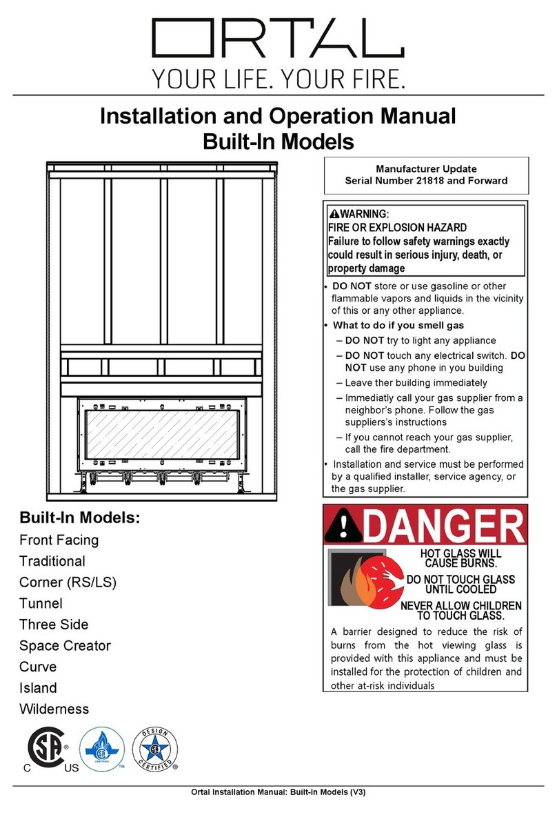
Instruction for Burner 30 Models:
Clear 40, Clear 40 RS/LS/TS, Clear 40 H
Clear 40 Tunnel, Stand Alone 40 TS
The Ortal direct vent appliances have been tested and approved by CSA for safety and
efficiency for use with either Natural Gas (NG) or Propane (LP).
WARNINGS
WARNING:
The direct vent system appliance must be installed as an OEM installation in
manufactured homes (USA only) or an aftermarket permanently located, or a mobile
home, where not prohibited by local codes and must be installed in accordance with
Manufacturer's instructions and the Manufactured Home Construction and Safety
Standard, Title 24 CFR, Part 3280, in the United States, or the Standard for Installation
in Mobile Homes, CAN/CSA Z240 MH Series, in Canada.
If the information in these instruction is not followed exactly a fire or explosion may
result cau ing property damage, personal injury or death.
Do not store or use gasoline or other flammable vapors and liquids in the vicinity of this
appliance.
SAVE THESE INSTRUCTIONS
Make yourself fully aware of all the following instructions and the many features of the
Ortal direct vent gas fireplace appliance.
INSTALLER: Leave this manual with the applian e.
OWNER: Keep this manual for future reference.
WARNING: Glass Handling
The glass must ONLY be removed by an authorized &/or qualified installer. The
authorized technician should ONLY remove the glass with the glass vacuum holders
supplied b the manufacturer. Lower the glass to rest in the special
wooden/polyurethane support provided, and fit the second support to the upper edge of
the glass. This is to pre ent damage to the glass edges.
Step 1. Place the support on the floor below the glass to be removed.
Step 2. Remove the glass using the vacuum holder, and immediately place it in the
support.
Step 3. Place the second support on the upper edge of the glass. The glass can
now be rested safely.
WARNING: Electrical Grounding
These Direct Vent appliances must be electrically grounded in accordance with the
local codes or, in the absence of local codes, with National Electric code, ANSI/NFPA
70, or the Canadian Ele tric Code, CSA C22.1.
WARNING: Gas Appliance
This applian e is only for use with the type of gas indicated on the rating plate. These
appliances are not convertible for use with other gases, unless a certified kit is used
and the con ersion is performed by an authorized qualified technician.
Applicable standards are Vented Gas fireplace heaters ANSI Z21.88 / CSA 2.33a and
gas-fired appliances for use at high altitudes CAN/CGA 2.17-M91.
WARNING: Installation and Service
Installation and service must be performed by an authorized qualified installer service
agency or gas supplier.
Any alteration to the product that causes soot or carbon to form and results in damage
is not the responsibility of the manufacturer.
In the case of models supplied with a door fitted in the frame of the heater, ONLY an
authorized qualified installer may open this door. The end user must NOT open the
door, as this may be unsafe and may result in voiding the manufacturer’s warranty.
ORTAL Heating Solutions Ltd.
INSTALLATION & OPERATION MANUAL
Instruction for Burner 30 Models:
Clear 40, Clear 40 RS/LS/TS, Clear 40 H
Clear 40 Tunnel, Stand Alone 40 TS
The Ortal direct vent appliances have been tested and approved by CSA for safety and
efficiency for use with either Natural Gas (NG) or Propane (LP).
WARNINGS
WARNING:
The direct vent system appliance must be installed as an OEM installation in
manufactured homes (USA only) or an aftermarket permanently located, or a mobile
home, where not prohibited by local codes and must be installed in accordance with
Manufacturer's instructions and the Manufactured Home Construction and Safety
Standard, Title 24 CFR, Part 3280, in the United States, or the Standard for Installation
in Mobile Homes, CAN/CSA Z240 MH Series, in Canada.
If the information in these instruction is not followed exactly a fire or explosion may
result cau ing property damage, personal injury or death.
Do not store or use gasoline or other flammable vapors and liquids in the vicinity of this
appliance.
SAVE THESE INSTRUCTIONS
Make yourself fully aware of all the following instructions and the many features of the
Ortal direct vent gas fireplace appliance.
INSTALLER: Leave this manual with the applian e.
OWNER: Keep this manual for future reference.
WARNING: Glass Handling
The glass must ONLY be removed by an authorized &/or qualified installer. The
authorized technician should ONLY remove the glass with the glass vacuum holders
supplied b the manufacturer. Lower the glass to rest in the special
wooden/polyurethane support provided, and fit the second support to the upper edge of
the glass. This is to pre ent damage to the glass edges.
Step 1. Place the support on the floor below the glass to be removed.
Step 2. Remove the glass using the vacuum holder, and immediately place it in the
support.
Step 3. Place the second support on the upper edge of the glass. The glass can
now be rested safely.
WARNING: Electrical Grounding
These Direct Vent appliances must be electrically grounded in accordance with the
local codes or, in the absence of local codes, with National Electric code, ANSI/NFPA
70, or the Canadian Ele tric Code, CSA C22.1.
WARNING: Gas Appliance
This applian e is only for use with the type of gas indicated on the rating plate. These
appliances are not convertible for use with other gases, unless a certified kit is used
and the con ersion is performed by an authorized qualified technician.
Applicable standards are Vented Gas fireplace heaters ANSI Z21.88 / CSA 2.33a and
gas-fired appliances for use at high altitudes CAN/CGA 2.17-M91.
WARNING: Installation and Service
Installation and service must be performed by an authorized qualified installer service
agency or gas supplier.
Any alteration to the product that causes soot or carbon to form and results in damage
is not the responsibility of the manufacturer.
In the case of models supplied with a door fitted in the frame of the heater, ONLY an
authorized qualified installer may open this door. The end user must NOT open the
door, as this may be unsafe and may result in voiding the manufacturer’s warranty.
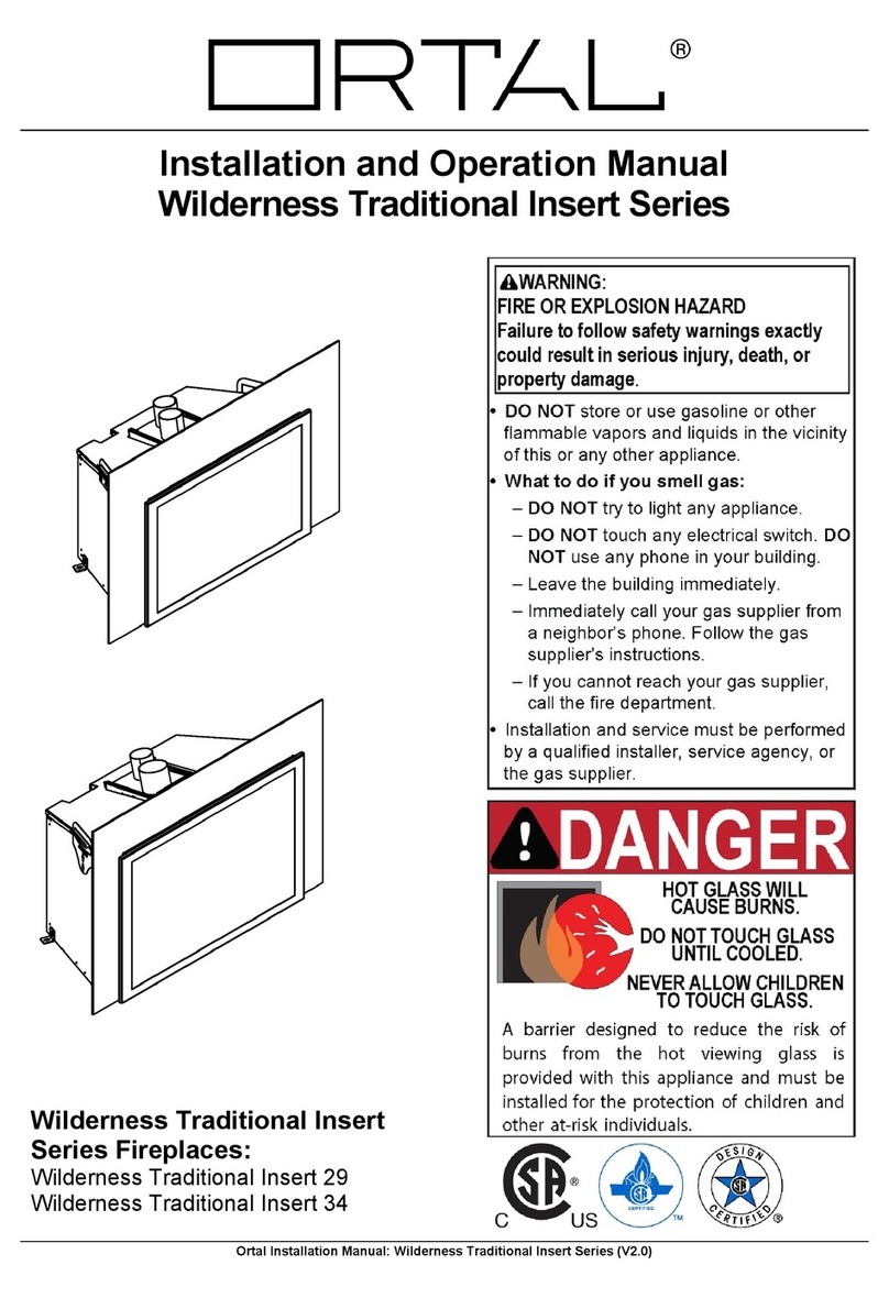
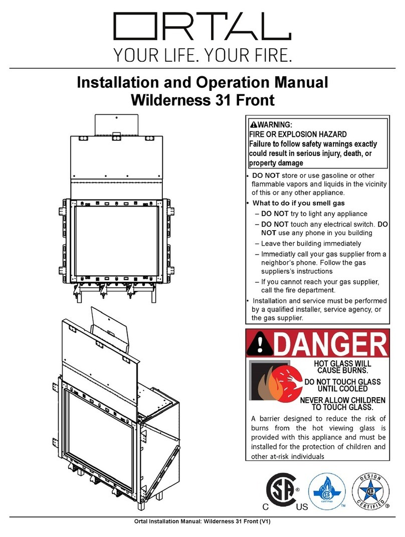
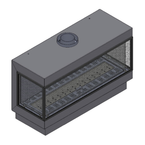
This manual covers the following appliances:
Single burner:
Clear 40 RS/LS/TS/Tunnel, Stand Alone 40 TS, Clear 40H90 RS/
LS/TS/Tunnel,
Clear 40H70 RS/LS/TS/Tunnel, Small Square, Corner Classic/ Modern , 4 glass
Island, Clear 75 RS/LS/TS, Stand Alone 75 /TS, Space Creator 75, Clear 75 Hark
RS/LS/TS, Clear 75x65 /Tunnel, Clear 60x80 /Tunnel, 60x80 OVAL, Classic F
75/80, Clear 80 RS/LS/TS, Clear 80H70 RS/LS/TS, Clear 110 RS/LS/TS/Tunnel,
Stand Alone 110, Clear 110H /Tunnel, Clear 130 RS/LS/TS/Tunnel, Space Creator
120, Island 130, 130 Top, Clear 150 RS/LS/TS/Tunnel, Space Creator 150, Stand
Alone 150, Clear 170 RS/LS/TS/Tunnel, Clear 200 RS/LS/TS/Tunnel, Space
Creator 200, Clear 250 RS/LS/TS/Tunnel, Clear 200H70 RS/LS/TS
Two burners:
Clear 250 RS/LS/TS/Tunnel, 4 glass 2 burners Clear 350 RS/LS/
TS/Tunnel, Clear 300H80 RS/LS/TS, Clear 400 RS/LS/TS/Tunnel, Clear 400H80
RS/LS/TS, Island 400
Contents
GENERAL INFORMATION . . . . 4
Important Safety Notice . . . . 4
General Fitting Information . . . 5
Battery type (Remote Versions only) . . 5
INSTALLER INFORMATION . . . . 5
Ventilation . . . . . 5
General Balanced Flue notes . . . 6
Terminal Locations Wall mounting . . 8
Terminal Locations Roof termination . . 9
Commissioning the appliance . . . 10
Servicing Instructions . . . . 10
Spare parts 11
Troubleshooting. . . . . 12
Countries of destination 13
Table B-2 Double Category 15
Instructions for changing burner from NG to LPG 16
TECHNICAL INFORMATION . . . . 21
Technigas CE approval test results 21
Contents- Single Step Burner (N) 21
Contents- Double Step Burner (D) 22
minimum clearances to combustibles materials . 23
DECORATION ARRANGEMENT . . . 30
English Branch . . 31
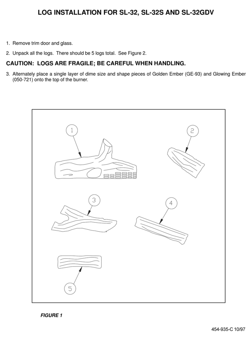
Logs (5 pes set) . . 36
White Little Stons . . 41
Large Pebbles . . 45
4
NEW LOGS ( 6 pcs SET) 1 SET . . 49
Flue Design Options . . 54
Automatic Valve information . . 59
This appliance has a ceramic Fire-bed arrangement; this contains Refractory
Ceramic Fibres, which are man-made vitreous silicate bres. Excessive exposure
to these materials can cause irritation to eyes, skin and respiratory organs. Hence
we recommend that when handling these materials the release of dust should be
kept to a minimum. During installation and servicing we recommend that a HEPA
ltered vacuum be used to remove any dust and soot in and around the re. If any
of the ceramic re-bed components need to be replaced we recommend that the
removed parts be sealed in a heavy-duty polythene bag, and be labelled as RCF
waste. RCF is not “Hazardous waste” and can be disposed of at a licensed tipping
site for the disposal of industrial waste.
The appliance incorporates a permanent pilot. This is located on the front of the
burner, and must not be adjusted by the installer. This system must not be put out
of operation, and if any parts require changing, only original manufacturer parts
shall be used.
This appliance is designed to be used either Natural or LPG gas however, each
individual appliance is only capable of running off the type of gas specied at the
time of purchase. It is important to note that once a type of gas has been specied
the stove cannot run off any other type. The type of gas that your stove is capable
of burning is stated on the data information panel.
This appliance has been designed, tested and approved to meet standards in place
for product use, performance and safety. Installation of your appliance must comply
with current building regulations. It is therefore recommend that a registered gas
installer be employed for this task. The engineer will provide you with information
about the safety limits of the installation and should x a notice plate in a place
where it can be readily seen.
This appliance is designed as an efcient heating device and consequently all body
parts become very hot in use. Except for the control knob and control access door,
which are designed to stay cool, all other parts are working surfaces and should
not be touched.
The glass and frame on this appliance acts as a reguard conforming to BS: 1945
– 1971 and satises the Heating Appliance (Fireguards) regulations 1991. No
part of the window or frame should be permanently removed. It does not give full
protection for young children or the inrm, extra protection should be considered for
these conditions conforming to BS 6539 or BS 6778.
Bearing in mind that the heat given off by this appliance may affect articles placed
close to it, curtains should not be placed within 30cm.
The appliance is not designed as a dryer. It is not therefore recommended that the
appliance be used in such a manner. Do not place any articles within 30cm of this
appliance as this may result in damage to the articles.
The installation must be carried out in accordance with the following regulations:
