OSD NETWORKS OSD2183P User manual

OSD2183P / PW
Micro 10/100/1000Base-T to 100/1000Base-X
Media Converter with IEEE802.3af/at/bt
& PoH PoE Source
Operator Manual


PAGE 3 10120801
OSD2183P / PW Operator Manual
INDEX 1
1TECHNICAL SUMMARY ................................................................................................4
1.1 BRIEF DESCRIPTION.................................................................................................4
1.1.1 OVERVIEW ...........................................................................................................................4
1.1.2 FEATURES AND BENEFITS ................................................................................................4
1.2 TYPICAL SYSTEM DESIGN........................................................................................5
1.3 TECHNICAL SPECIFICATIONS..................................................................................6
1.4 FRONT /REAR PANEL LAYOUT ................................................................................8
2INSTALLATION AND OPERATION...............................................................................9
2.1 INTRODUCTION..........................................................................................................9
2.2 INSTALLATION............................................................................................................9
2.2.1 WARNING AND PRECAUTIONS..........................................................................................9
2.2.2 DRAWINGS AND DIMENSIONS.........................................................................................10
2.2.3 LOCATION ..........................................................................................................................11
2.2.4 POWER SUPPLY CONNECTIONS.....................................................................................11
2.2.5 LED INDICATORS...............................................................................................................12
2.2.6 CONTROLS.........................................................................................................................13
2.2.7 FITTING SFP CONNECTORS ............................................................................................15
2.3 SINGLE/DUAL SIGNATURE PD OPERATION .........................................................16
2.3.1 SINGLE SIGNATURE PD....................................................................................................16
2.3.2 DUAL SIGNATURE PD.......................................................................................................16
2.4 OPERATION..............................................................................................................17
2.4.1 CONNECTIONS..................................................................................................................17
3MAINTENANCE ............................................................................................................18
3.1 INTRODUCTION........................................................................................................18
3.2 EXTERNAL INSPECTION .........................................................................................18
3.3 ROUTINE MAINTENANCE........................................................................................18
4WARRANTY..................................................................................................................19
4.1 WARRANTY PERIOD................................................................................................19
4.2 REPAIRS ...................................................................................................................19
4.2.1 WARRANTY REPAIRS .......................................................................................................19
4.2.2 OUT-OF-WARRANTY REPAIRS.........................................................................................19
4.2.3 SITE REPAIRS....................................................................................................................19
4.2.4 EXCLUSIONS .....................................................................................................................19
FIGURE 1: TYPICAL SYSTEM DESIGN...................................................................................5
FIGURE 2: PANEL LAYOUT......................................................................................................8
FIGURE 3: MOUNTING DIMENSIONS ...................................................................................10
FIGURE 4: POWER SUPPLY CONNECTIONS ......................................................................11
FIGURE 5: PORT/LED.............................................................................................................12
FIGURE 6: CONTROLS...........................................................................................................13
FIGURE 7: 3-WAY DIP SWITCH .............................................................................................13
FIGURE 8: FITTING/REMOVING SFP CONNECTORS .........................................................15
FIGURE 9: SINGLE SIGNATURE PD......................................................................................16
FIGURE 10: DUAL SIGNATURE PD.......................................................................................16
TABLE 1: TECHNICAL SPECIFICATIONS................................................................................6
TABLE 2: POWER CONNECTION ..........................................................................................11
TABLE 3: LED FUNCTION.......................................................................................................12
TABLE 4: 3-WAY DIP SWITCH SETTINGS ............................................................................13
TABLE 5: POE MODE..............................................................................................................14

PAGE 4 10120801
OSD2183P / PW Operator Manual
1 TECHNICAL SUMMARY
1.1 BRIEF DESCRIPTION
1.1.1 OVERVIEW
The OSD2183P is a Power over Ethernet Gigabit Media Converter meeting the latest IEEE802.3bt
PoE specification with continued support for devices requiring IEEE802.3af/at and HDBase-T (PoH)
PoE. The fixed RJ45 ports is capable of providing 90W of power allowing the latest PoE devices such
as IP cameras, Wireless Access Points, microwave links and VOIP phones to be easily connected to
your network. With a compact design the OSD2183P can easily be mounted inside a network
enclosure or a Smart Pole using the DIN rail or wall mounting brackets provided. Optionally, the
OSD2183PW version can be powered from a 12VDC to 57VDC supply. A rugged IP30 casing, fanless
design and wide operating temperature range from -40 to +75°C make this product ideally suited for
use in a wide range of harsh industrial environments.
1.1.2 FEATURES AND BENEFITS
▲Complies with IEEE802.3i/802.3u/ 802.3ab
10/100/1000Base-T, IEEE802.3u 100Base-
Fx, IEEE802.3z 1000Base-Lx/Sx standards
▲Has one fixed copper port and one
100Mbps/1000Mbps SFP port
▲Auto MDI/MDIX on copper port (supports
both straight through and crossover cables)
▲Complies with IEEE802.3af/at/bt and
HDBaseT (PoH) standards
▲Provides up to 90W to the RJ45 port
▲User selectable PoE mode setup via Push
Button
▲Powered by non-critical 46 to 57VDC
supplies for OSD2183P or 12 12 to 57VDC
for OSD2183PW (voltage booster version)
▲Operates over the temperature range of -
40°C to +75°C
▲Supports 10KB jumbo frames
▲User selected SFP module allows for a
fiber link over 1 or 2 multimode or
singlemode fibers over a range of
distances up to 120km (over singlemode
fiber)
▲DIN rail or wall mounting


PAGE 6 10120801
OSD2183P / PW Operator Manual
1.3 TECHNICAL SPECIFICATIONS
TABLE 1: TECHNICAL SPECIFICATIONS
Hardware
Ethernet
1 x 10/100/1000Base-T RJ45, IEEE802.3i/802.3u/802.3ab
Jumbo Frame Support
10KB
SFP
1 x Gigabit SFP ports (100Mbps or 1000Mbps user selectable)
Optical Data Interface
IEEE802.3z 1000Base-Lx/Sx, IEEE802.3u 100Base-Fx
PoE (user configurable via GUI)
IEEE802.3af/at, IEEE802.3bt, PoH, bt legacy mode
Enclosure Protection Class
IP30
Installation
DIN rail, wall mount or desktop
DIP Switch
3 way DIP switch for configuration
Power Requirements
OSD2183P
Input Voltage: +46VDC to +57VDC @ 8W +PoE output power for PD
devices
Output PoE Voltage: Vin - Vdrop
Power Requirements
OSD2183PW
Input Voltage: +12VDC to +57VDC @ 15W +PoE output power for PD
devices
Output PoE Voltage: 56 to 57V - Vdrop
Output PoE Vdrop per port
PoE voltage drop per port <0.5V @ 30W, <1V @ 60W, <1.5V @ 90W
Power Connector
2 way 3.5mm terminal block
Indicators
1 x Copper Link on RJ45
1 x Copper Activity on RJ45
1 x PoE Power On/Off
4 x PoE Mode
1 x Power
1 x SFP Link/Speed on SFP
Environmental
-40 to +75ºC
Relative Humidity
0 to 95% non-condensing
Dimensions
90W x 88D x 49H mm
Weight
380g
Warranty
Warranty Period
5 years
MTBF (Ground Benign
Environment, 30ºC)
472,000 hours for OSD2183P
424,000 hours for OSD2183PW

PAGE 7 10120801
OSD2183P / PW Operator Manual
PAGE 8 10120801
OSD2183P / PW Operator Manual
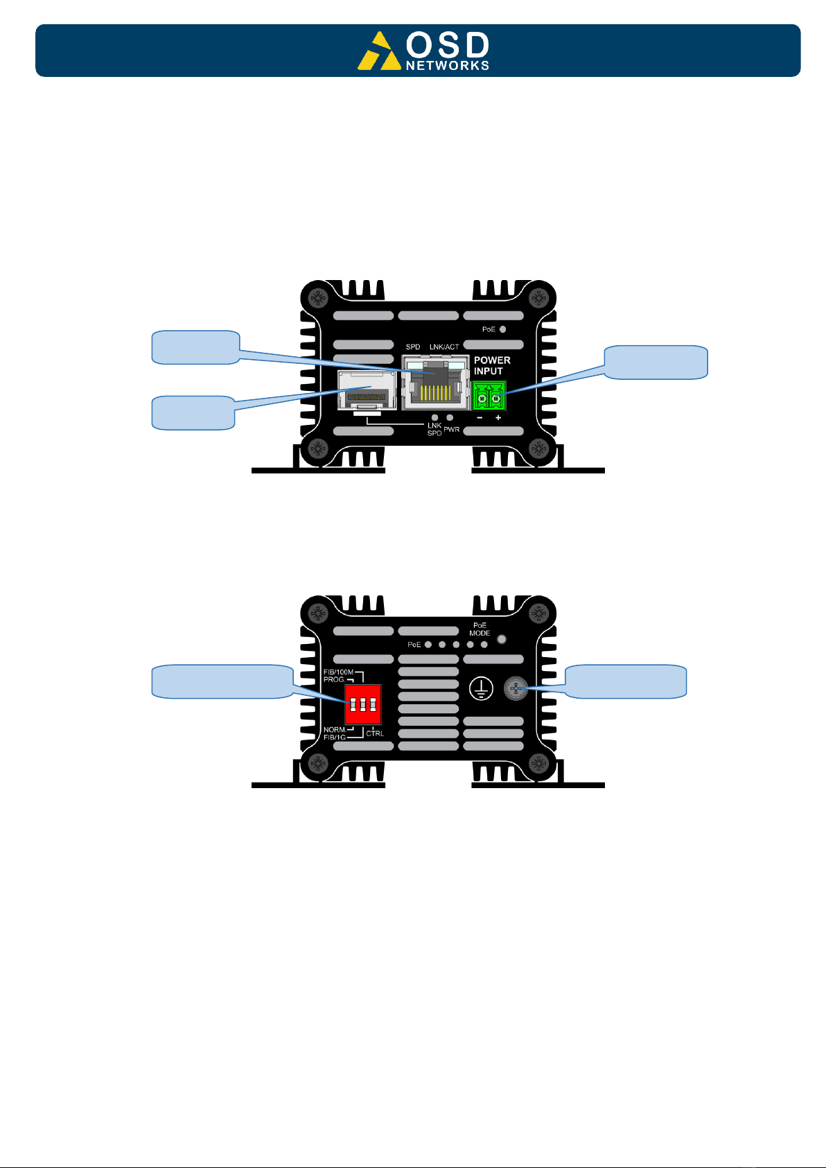
1.4 FRONT / REAR PANEL LAYOUT
Front Panel: One fixed copper port for 10/100/1000Base-T, one SFP port and a 2-way
terminal block power connector
Rear Panel: 3-way DIP switch.
FIGURE 2: PANEL LAYOUT
Front Panel
Rear Panel
RJ45 Port
Power Input
SFP Port
3-Way DIP switch
Earth Screw

PAGE 9 10120801
OSD2183P / PW Operator Manual
2 INSTALLATION AND OPERATION
2.1 INTRODUCTION
This section outlines the methods required to install and operate the OSD2183P/PW
successfully. It should be studied carefully if damage to the equipment or poor results are to
be avoided.
This equipment has been fully tested prior to dispatch and is ready for immediate operation.
However, it is advisable to check for external transportation damage before operation. If
damage is evident, return the unit with the packaging to your supplier immediately.
2.2 INSTALLATION
2.2.1 WARNING AND PRECAUTIONS
▲ELECTROMAGNETIC COMPATIBILITY
WARNING: This is a Class A product. In a domestic environment this product may cause
radio interference in which case the user may be required to take adequate measures.
▲OPTICAL OUTPUT OPERATION
WARNING: Laser Safety: Class 1 Laser Product per IEC/EN 60825-1:2014 standard.
Class 1
The OSD2183P/PW is a Class 1 laser product.
PRECAUTIONS
▲All service personnel should be provided training as to the hazards of direct viewing
of laser radiation and of the precautionary measures during servicing of equipment
▲Areas where laser products are installed should be restricted in access to trained
service personnel only and appropriate warning signs posted in the work area.
▲All laser apertures should be covered by protective covers when not connected to
optical fibers. Never leave outputs uncovered.
▲Laser equipment should be positioned above or below eye level where possible.
Apertures should be positioned away from personnel.
▲Protective eyewear should be worn in the vicinity of laser equipment.

PAGE 10 10120801
OSD2183P / PW Operator Manual
2.2.2 DRAWINGS AND DIMENSIONS
The OSD2183P/PW is designed to be wall mounted onto a DIN-Rail (35mm top hat) fixture or
by using 4 x M4 captivated screws (DIN Rail mount requires removal and flanges repositioned
–see below). The unit dimensions (excluding connectors, SFPs, etc) is shown in below.
Wall Mount
DIN Mount
FIGURE 3: MOUNTING DIMENSIONS
Bottom View
Supplied
DIN clip + 4
x screws
With DIN clip
fitted
PAGE 11 10120801
OSD2183P / PW Operator Manual
2.2.3 LOCATION
As with any electrical device, the OSD2183P/PW should be placed where the switch will not
be subjected to extreme temperatures, humidity, or electromagnetic interference. Specifically,
the site selected should meet the following requirements:
•The ambient temperature should be between -40°C to 75°C.
•The relative humidity should be less than 95 percent, non-condensing.
•Surrounding electrical devices should not exceed the electromagnetic field (RFC)
standards.
•Make sure that the switch receives adequate ventilation. Do not block the ventilation
holes on any side of the switch.
Note: Without proper cooling and control (lowering) of ambient temperature, the components
within the OSD2183P/PW can be subject to increased heat shortening the longevity and
reliability. It is thus good engineering practice to ensure the unit is installed in a well-ventilated
area.
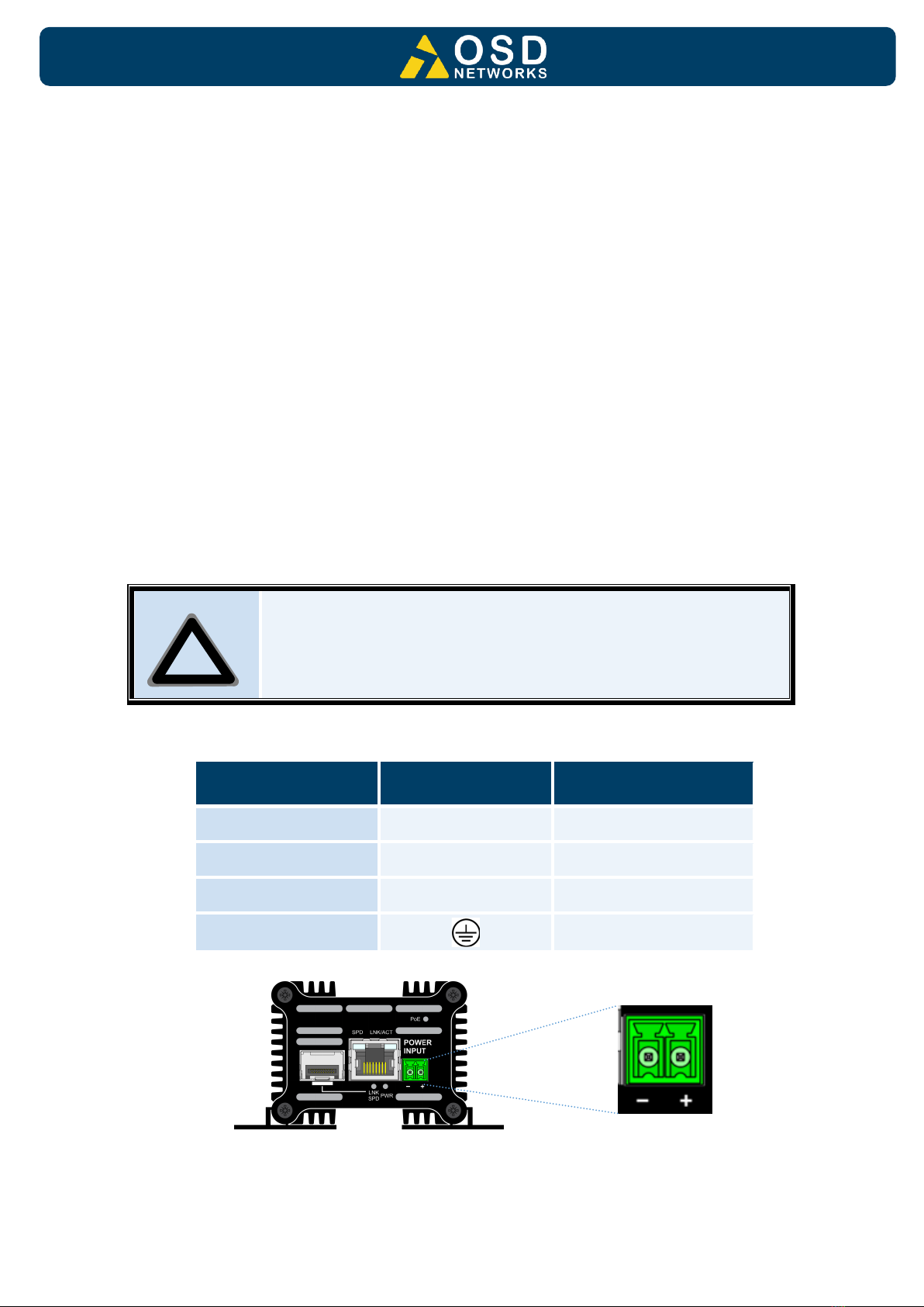
2.2.4 POWER SUPPLY CONNECTIONS
IMPORTANT! There are two options available for the OSD2183P: The OSD2183P and
OSD2183PW. The Table below (Table 2) indicates the power requirements for each. They
both require external DC power which is connected via the 2-way terminal block located on
the front panel as shown in Figure 4.
CAUTION
It is highly recommended to wait about 30 seconds before reconnecting
the PD after the PD has been disconnected from the unit. This will prevent
a high inrush current being applied to the unit. Although the
OSD2183P/PW has a high inrush current tolerance (400mA for 50 to 75ms
as per the IEEE802.3at standard), inrush currents higher than 1.5A may
damage the device.
TABLE 2: POWER CONNECTION
OSD Version
External Power
Pin
Specification
OSD2183P
+
+46VDC to +57VDC @ 8W
OSD2183PW
+
+12VDC to +57VDC @ 15W
-
0V
Chassis Ground
connection point
*≥52VDC recommended for PoE+ or ≥ 55VDC for 60W PoE
FIGURE 4: POWER SUPPLY CONNECTIONS
Front Panel
!
PAGE 12 10120801
OSD2183P / PW Operator Manual
2.2.5 LED INDICATORS
FIGURE 5: PORT/LED
TABLE 3: LED FUNCTION
No
FUNCTION
Indicator
LED
Colour
On
Off
Blinking
PoE
Green(1)
PoE Enable
No PoE
Invalid Device(2)
LNK/ACT
Amber
Copper Link Activity
No Copper Link
Activity(3)
SPD
Green
Copper
Speed
1Gbps
10/100Mbps
-
LNK SPD
Amber
Fiber
Speed
100Mbps
No Optical Link
-
Green
1Gbps
PWR
Green
Power On
Power Off
-
PoE Mode
Green
See Table 5
See Table 5
-
PoE
Off
N/A
N/A
N/A
Notes: (1) When PoE LED is on it indicates that the unit is supplying power to the PSE
(2) Invalid device –No PoE output
(3) Activity indicates traffic for copper port
PAGE 13 10120801
OSD2183P / PW Operator Manual
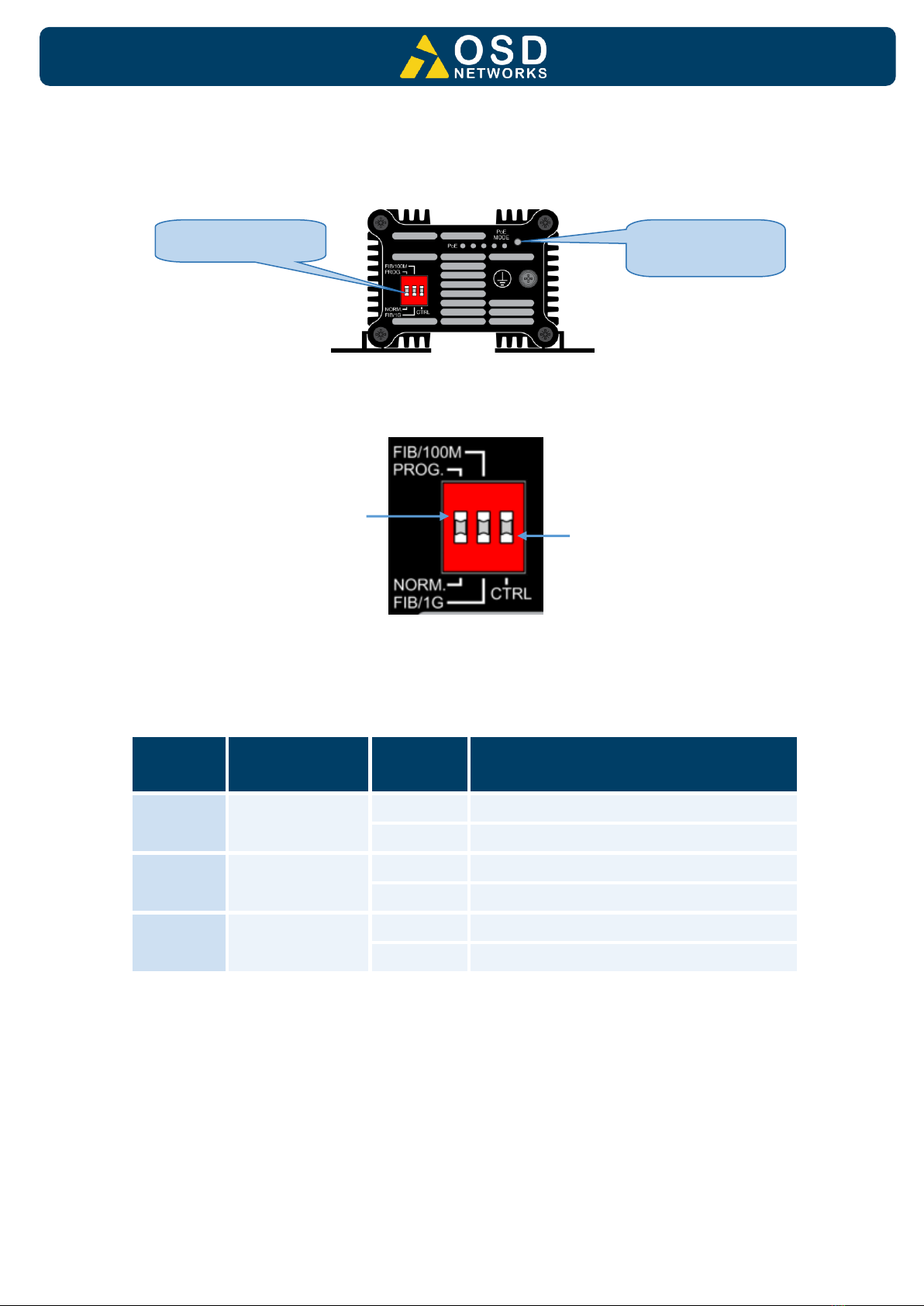
2.2.6 CONTROLS
The OSD2183P/PW has a number of control functions: a 3-Way DIP Switch and a PoE Mode
push button.
FIGURE 6: CONTROLS
FIGURE 7: 3-WAY DIP SWITCH
TABLE 4: 3-WAY DIP SWITCH SETTINGS
SWITCH
NUMBER
DESCRIPTION
SWITCH
POSITION
FUNCTION
1
Not In Use
OFF
User Mode*
ON
-
2
Optical Port
Speed
OFF
1000BASE-X*
ON
100BASE-X
3
CTRL
OFF
PoE Disabled
ON
PoE Enabled*
* Default settings.
ON
OFF
1
2
3
3-Way DIP Switch
PoE Mode Push
Button

PAGE 14 10120801
OSD2183P / PW Operator Manual
PoE Mode Push Button
The PoE Mode push button is used to control the PoE settings. Pressing the push button will
cycle through the different modes as set out in the table below.
TABLE 5: POE MODE
LED
NUMBER
DESCRIPTION
MODE
FUNCTION
1
BT Mode
4 Pair power output, 90W Max, High Inrush
Current Mode off
2
PoH Mode
4 Pair power output, 90W Max, High Inrush
Current Mode off
3
BT Mode
2 Pair power output, 30W Max, High Inrush
Current Mode off
4
Custom
Mode
There are no customized settings - this mode
will be skipped.

PAGE 15 10120801
OSD2183P / PW Operator Manual
2.2.7 FITTING SFP CONNECTORS
Care should be taken when inserting/removing the SFP connectors from SFP port as SFP
modules are Electrostatic (ES) sensitive and Electrostatic Discharge (ESD) precautions
should be taken when installing. Ensure that the SFP is fully engaged and latched into
position.
Inserting SFP –Ensure that the SFP lever is in the locked position and insert into appropriate
SFP port. Gently push the SFP until it locks into place. Remove plastic/rubber dust cap and fit
fiber cable or RJ45 plug.
Removing SFP –Remove fiber connector or RJ45 plug. Pull the SFP lever down to unlock
SFP from housing. Using the lever, gently pull the SFP out.
Fiber SFP
Copper SFP
FIGURE 8: FITTING/REMOVING SFP CONNECTORS
Inserting
SFP
Removing
SFP
1
2
Inserting
SFP
Removing
SFP
1
2

PAGE 16 10120801
OSD2183P / PW Operator Manual
2.3 SINGLE/DUAL SIGNATURE PD OPERATION
The OSD2183P/PW supports single, dual or either single/dual signature PD by automatically
detecting the user PD signature.
2.3.1 SINGLE SIGNATURE PD
A “single signature PD” shares the same detection signature, classification signature, and
maintains power signature between both pair sets.
FIGURE 9: SINGLE SIGNATURE PD
2.3.2 DUAL SIGNATURE PD
A “dual signature PD” has independent detection signatures, classification signatures, and
maintains power signatures on each pair set. It enables the load to work with two pair PSEs
eg. A surveillance camera built with dual signature PD can have one pair connected to the
camera and the other pair to a fan or heater. Note that dual signature PDs require two parallel
PD interfaces, one for each pair set, where the power from the two PSEs are summed after
each PD interface ie Camera (25W) + fan (10W) = 35W from one port.
FIGURE 10: DUAL SIGNATURE PD

PAGE 17 10120801
OSD2183P / PW Operator Manual
2.4 OPERATION
When using the OSD2183P/PW for the first time, check that the unit is in good condition with
no visible damage.
Upon power up check that the indicators illuminate accordingly on power up (see Table 3).
2.4.1 CONNECTIONS
For RJ45 connection use Category 5 (CAT5) or higher. Length should be no more than 100
meters.
For singlemode fiber connections, fiber used must be 9/125μm singlemode fiber.
For multimode fiber connections, fiber used must be 50/125μm or 62/125μm multimode fiber.
Plug in the appropriate connectors for system configuration;
–RJ45 cable to fixed copper ports (port 1 and 2) and copper SFP modules
–LC or SC fiber cable to fiber SFP modules.

PAGE 18 10120801
OSD2183P / PW Operator Manual
3 MAINTENANCE
3.1 INTRODUCTION
The following section outlines the fault-finding procedure for the OSD2183P/PW modems.
Please take note of the following:
▲Personnel without appropriate training should not attempt any maintenance except that
outlined below.
▲If further maintenance is attempted you are warned that every care should be taken to
ensure that internal measurements made while the equipment is operational are taken
carefully as some components within the unit are expensive and may be damaged by
failure of any portion of their support circuitry.
▲Some components within the unit are Electrostatic (ES) sensitive and Electrostatic
Discharge (ESD) precautions should be taken when performing maintenance upon the
unit.
3.2 EXTERNAL INSPECTION
Visually check for the following:
▲Check that the correct power source is connected to the power socket.
▲Check that the Ethernet cables are connected to the modem correctly and that the distant
OSD2183P/PW modem has been connected correctly to any external equipment.
▲Inspect the optical connectors (for fiber SFP option) for any contamination and clean
using isopropyl alcohol and a lint free tissue if any contamination is detected.
3.3 ROUTINE MAINTENANCE
▲There is no routine maintenance required with the OSD2183P/PW.

PAGE 19 10120801
OSD2183P / PW Operator Manual
4 WARRANTY
Thank you for purchasing equipment designed, manufactured and serviced by Optical
Systems Design (OSD). OSD warrants that at the time of shipment, its products are free from
defects in material and workmanship and conforms to specifications. Our Warranty conditions
are outlined below:
4.1 WARRANTY PERIOD
For warranty period, please contact your local OSD distributor.
4.2 REPAIRS
Optical Systems Design reserves the right to repair or replace faulty modules/units. Please
obtain a “Return Material Authorisation” (RMA) form and number before returning goods.
Goods must be returned in adequate packing material to Optical Systems Design,
Warriewood or its nominated authorised representative, for all repairs.
4.2.1 WARRANTY REPAIRS
Return shipments to OSD shall be at customer's expense and freight back to the customer
will be at OSD expense.
4.2.2 OUT-OF-WARRANTY REPAIRS
OSD reserves the right to repair or replace any faulty goods. Freight costs and insurance for
both journeys are met by the user. All equipment repaired by OSD will have a 3-Month
Warranty from the date of dispatch.
4.2.3 SITE REPAIRS
By agreement site repairs may be undertaken for which out of pocket, hotel and travel
expenses will be charged.
4.2.4 EXCLUSIONS
This warranty does not apply to defects caused by unauthorized modifications, misuse, abuse
or transport damage to the equipment. All modifications to OSD’s standard product will need
written authorization and will be charged at normal repair rates. All modifications are to be
carried out by OSD Technicians. Warranty is void if unauthorized removal and/or tampering
with serial number and/or repair labels is evident.

Optical Systems Design Pty. Ltd.
7/1 Vuko Pl. Warriewood 2102
P.O. Box 891 Mona Vale
N.S.W. Australia 2103
Telephone: +61 2 9913 8540
Facsimile: +61 2 9913 8735
Email: s[email protected]m.au
Web Site: www.osd.com.au
Printed in Australia
This manual suits for next models
1
Table of contents
Popular Media Converter manuals by other brands

Atlona
Atlona OmniStream AT-OMNI-121 manual

The Telios Alliance
The Telios Alliance Z/IPStream R/1 Quick start setup guide

Omnitron Systems
Omnitron Systems OmniConverter GPoE/SE user manual

CYP
CYP CHDBT-1H7CPL Operation manual

Moxa Technologies
Moxa Technologies NPort 5110A Quick installation guide

ATEN
ATEN VanCryst VC160A user guide


