oset MX-10 Mk.1 User manual

2
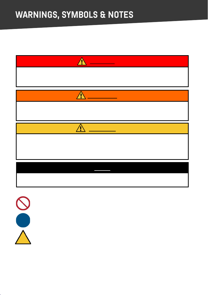
This Owner’s Manual uses the following symbols and terms to call your aenon to Dangers,
Warnings, Cauons and Notes, please read, understand and follow all of these noces.
Prohibited acon - safety sign that indicates forbidden behaviour.
Mandatory acon - safety sign that indicates a specic course of acon to follow.
Warning - safety sign that indicates a specic source of potenal harm
If you do not understand any of this important informaon, please contact your selling
dealer/distributor or the OSET Customer Service Department.
This document was prepared in accordance with IEC Guide 37:2012
Meaning: This term calls aenon to a Warning. This indicates a potenally hazardous
situaon which, if not avoided, could result in serious injury, in addion to property damage.
Read the text accompanying the warning to be aware of the specic hazard.
WARNING
Meaning: This term calls aenon to a Cauon. This indicates a potenally hazardous
situaon which, if not avoided, may result in minor injury and/or damage to equipment or
inadvertent system failure. Read the text accompanying the Cauon to be aware of the
specic hazard and avoid damage or system failure.
CAUTION
Meaning: This term calls aenon to a Danger. This indicates an imminently hazardous
situaon which, if not avoided, will result in death or serious injury. Read the text
accompanying the Danger to be aware of the specic hazard.
DANGER
Meaning: This term calls aenon to a Note. The text accompanying a Note provides helpful
or other important related informaon.
NOTE
3
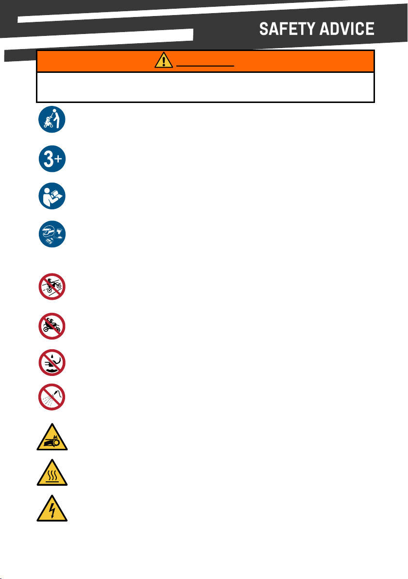
OSET Electric Bikes are designed for o road use only and must not be used on public
roads or sidewalks. Please check and obey all local laws.
OFF ROAD USE ONLY!
Your OSET is designed for one rider only, more than one rider will over stress the
bike.
OPERATOR ONLY - NO PASSENGERS!
This vehicle must be used in the presence of adult supervision to ensure that safe
riding pracces are established and followed.
ADULT SUPERVISION REQUIRED
This bike is not design to be used by children under 3 years old.
NOT SUITABLE FOR CHILDREN UNDER THREE YEARS OF AGE
This manual contains IMPORTANT INFORMATION that every owner must fully
understand.
READ USER MANUAL BEFORE USE
OSET electric bikes must be charged indoors, in a well venlated area.
NO LIQUIDS NEAR CHARGER PLUG
Do not clean your bike or baery with water under pressure. Such as a hose, jet
wash, power washer or steam cleaner. Do not immerse vehicle in water.
DO NOT SPRAY WITH WATER
WEAR A HELMET, BOOTS, GLOVES LONG SLEEVE JERSEY
The potenal hot surfaces are highlighted on page 6.
DO NOT TOUCH HOT SURFACES
Your OSET is baery powered, ensure power is isolated before cleaning, maintenance
or removing baeries.
DO NOT TOUCH ELECTRICAL CONTACTS
Risk of entrapment and entanglement if moving parts are touched.
DO NOT TOUCH MOVING PARTS
The rider must wear a helmet & appropriate safety gear every me. OSET also
recommend wearing protecve armour. Do not use bike with loose clothing, long
exposed hair or laced shoes.
KEEP INSTRUCTIONS FOR FUTURE REFERENCE
THIS OSET IS NOT A TOY
Failure to obey all of the warnings & instrucons contained in this manual may result in
serious injury and permanent damage to your OSET.
WARNING

4
Thank you for purchasing an OSET Electric Trials Bike.
This is a serious piece of machinery designed for use by children in fully controlled and safe
environments. As the purchaser/owner of the machine, YOU are the responsible adult with
the task of keeping the rider(s) safe at all mes.
This manual contains IMPORTANT INFORMATION that every owner must fully understand to
ensure opmum performance from your new OSET, and to ensure safe operaon, it is
important to fully understand the features of the machine.
If you defer this task to another adult, it is YOUR RESPONSIBILITY to pass this owners manual
and all relevant informaon to whoever will take on this role, and ensure without queson
that the rider is controlled and taught in a safe manner.
Your OSET is very adjustable and can be specically set up for the rider. This motorcycle is
equipped with a speed liming device to restrict top speed. Use this device unl your child
becomes familiar with the operang of the motorcycle. Please do not allow the machine to
be used or adjusted by other children or adults. It is likely you know the abilies, levels of
concentraon and aenon span of the child you purchased the machine for. EVERY CHILD
IS DIFFERENT and it is impossible for you to properly supervise other children.
Your OSET is driven by a powerful electric motor. The control dials MUST be adjusted to suit
the abilies of the rider. Please remember that even when the speed is set to a slow seng,
if the power and response are at high seng, the full torque of the bike will sll be available.
This means that opening the throle will propel the machine to the set speed very quickly.
Your OSET has great capabilies, and can grow with the skills of the rider to very high levels,
but it is IMPERATIVE that the responsible adult controls the enre learning process and gives
full aenon at all mes.
IT IS YOUR RESPONSIBILITY TO FORESEE ALL POTENTIAL SITUATIONS AND CONTROL THE
RIDING ENVIRONMENT ACCORDINGLY.
This means not just the machine and the rider, but also the riding terrain and environment.
OSET’s are amazingly capable compeon-ready bikes, and can be used from the
earliest stages of learning to ride all the way through to o road compeons. The secret of
learning to ride well is being able to ride a lot. OSET’s enable this to happen, and can make
the learning process very grafying for both the children and the adults. Thanks again for
purchasing an OSET, and we hope you, and your child, will enjoy the ride!
Ian Smith, President, OSET CORP.

5
Warning symbols - Page 2
Safety advice - Page 3
Important informaon - Page 4
Safety Advice - Page 6
Safety Responsibilies - Page 7
Serial number - Page 8
Bike Specicaons - Page 9
Unpacking and Assembly - Page 10
Dials - Page 13
Switches and Indicators - Page 14
Wheel Removal/Installaon - Page 15
Drive train/Seat removal - Page 16
Frame adjustment/Suspension - Page 17
Brake Adjustment - Page 19
Side Panel & Baery Removal - Page 20
Charging Instrucons - Page 21
Baery Guidance - Page 22
Baery Care and Disposal - Page 23
Bike Maintenance - Page 24
Motor Care and Bike Cleaning - Page 25
Build checklist - Page 26
Storage & Transport - Page 27
Troubleshoong - Page 28
Electrical Diagnosc Flow Chart - Page 29
Wiring Diagram - Page 30
Wiring - Page 31
Seng Up Your OSET for Riding - Page 32
Riding Instrucons & Safety Tips - Page 33
First Ride - Page 34
Safe Disposal - Page 35
Declaraons - Page 36
Limited Warranty - Page 37
Importer Contact Informaon - Page 40

6
HOT SURFACES
During extended periods of use or if your OSET is ridden hard then some parts will get hot,
see highlighted areas in the image below.
- Do not touch the brake rotors or motor before they have cooled down.
- Let the bike cool down before carrying out any work.
INTENDED USE
Your OSET has been designed to be used in sports motorcycle compeons, or in a
supervised and authorised pracce environment.
Please follow all safety notes in the manual and ensure riders are of the correct age and
weight, the bike is correctly maintained, riders are always supervised and the bike is ridden
in appropriate condions.
SAFETY MODE
If the motor gets too hot the controller will limit the power to the motor unl the
temperature reduces to a safe level. If the motor temperature reaches a level which may
damage the motor then all power to the motor will be removed. Allow the bike to cool for
15 minutes , turn the bike o/on and you will be able to resume riding.
If the controller believes that an electronic component is behaving abnormally it will enter a
safe mode and stop power to the motor. If this occurs, stop riding and check the bike for
obvious signs of damage or faults. Once you have resolved the problem to restart the bike
you simply need to turn the bike o and on again. If the problem persists please take your
bike to an authorised OSET dealer for inspecon.
Risk of burning. Allow bike to cool before touching hot
surfaces.
WARNING
Motor
Brake disks

7
Always follow the Pre-Ride Checklist before every ride.
Do not operate your OSET if any damage is apparent. Immediately contact your authorised
OSET retailer/distributor or OSET Customer Service.
Supervision: An adult must ALWAYS assess and approve the riding condions and the
bike preparedness before the bike is ridden. Always ensure the rider is cauous,
maintaining complete control and a reasonable speed. Ensure the terrain is suited to the
skills of the rider.
Helmets & Safety Are: Do not allow your OSET to be ridden without a helmet
approved by your countries’ governing body. Riders should also wear suitable riding
gloves, eye protecon and boots. Boots should NOT HAVE LACES. Shoe laces and loose
clothing or even long hair could potenally get caught in wheels, chains or sprockets.
Do not overload the bike: Exceeding the weight limitaons will adversely aect the
handling of the machine, and potenally cause damage.
It’s the law; obey it: Obey all laws. OSET bikes are for OFF-ROAD USE ONLY. OSET bikes
can not be used on public roads or sidewalks. The purchaser, owner, and/or riders of this
machine are directly responsible to know and obey all local, regional, and naonal laws
regarding the riding and use of this machine.
Do not sit on the bike when side stand is engaged in the downwards posion; This can
lead to damaging your machine, and yourself
Ensure charger is disconnected from bike before riding. Failure to do so will cause
damage to the bike and could result in injury.
Night me: Don’t ride aer dark or in low light condions.
Weather & Riding Condions: Bike brakes don’t work well when they’re wet. Please be
aware that distance to stop may double or triple over the distance that it takes under dry
condions. Ride more slowly and ancipate your stops by applying the brakes MUCH
earlier. Don’t allow children to ride on slopes that are too steep for their ability.
Before each ride, make sure that all bolts and nuts are fastened securely and that the
res are properly inated. Check that the throle and brake controls are operang
freely and adjust/lubricate the drive chain as necessary.
Please have your bike checked by a qualied mechanic AT LEAST once a year. It’s a small
investment in the well-being of the rider.
8
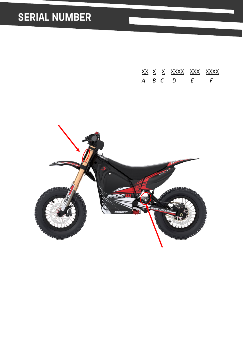
The individual idenfying serial number of the product can be found on the le hand side of
the head tube of the frame, as shown below.
The serial number will use the following format:
(A) Bike Category/Wheel size
(B) Bike Designaon
(C) Bike Specicaon
(D) Year of manufacture
(E) Batch ID
(F) Unique Serial
It is highly recommended to record the frame number and store this in a safe locaon and use
when contacng your local dealer or OSET customer services.
The motor serial number can be found on the motor as shown in the image above.

9
Performance:
- Maximum Speed - 22 mph -
- Weight Limit (Rider) - 88 lbs (40.0kg)
Gearing:
- 9T front sprocket, 54T rear. #219 chain.
Motor:
- 1400w 48v OSET Neodymium magnet DC motor.
Chassis:
- Frame & Swing Arm - Steel with adjustable geometry.
- Suspension (Front) - USD Coil sprung, adjustable rebound & compression.
- Suspension (Rear) - Spring & oil type, adjustable rebound.
- Wheels - 10 x 1.60’’, 28H alloy hubs.
- Tires - 2.5” x 10.0” front & 3.0’’ x 10.0’’ rear.
- Brakes - Hydraulic disc, 160mm rotors.
- Foot pegs - Cast Alloy, Red
- Handlebars - Alloy.
Controller:
- 48 volt, 3 Dial Controller with Thermal Cut-out.
- External speed, power & throle ‘map’ response dials.
Throle:
- Twist type with LED baery charge indicator.
Baeries:
- 1 x sealed 48V Lithium pack, with charging, discharging & diagnosc ports.
Keys, Dials and Ports:
- Key Switch and Magnec Kill switch.
- Throle map/response dial. Tuneable response.
- Speed dial. Overall speed adjustment.
- Power dial. Overall power adjustment.
Size:
- Wheelbase - 37.0” (940mm)
- Seat Height - Low (515mm), Mid (530mm), High (550mm)
- Ground Clearance - Low (170mm), Mid (185mm), High (200mm)
- Handlebar Height - Low (805mm), Mid (810mm), High (815mm)

10
Failure to properly assemble and adjust your bike prior to use may result in an accident
resulng in death, serious injury and/or property damage.
If you purchased your OSET in the carton, please carefully follow the instrucons below and
any supplemental instrucons to nish the assembly and adjustment of your OSET.
NOTE
DANGER
RECOMMENDED TORQUE VALUES
Where there are no other torque values stated please
use the recommended torque value table shown here.
1. Remove your OSET & Accessory pack from the box and check contents against the
following list:
1x Bike
1x Accessory Box containing:
1x Front mudguard (fender)
1x Baery charger c/w power lead & manual (if supplied)
1x Number board
4x Black cable es
1x Hex Key set (Allen keys)
1x Adjustable Spanner
1x Manual for air forks
1x Manual for rear shock
2. Place your OSET on a solid & level stand, with both wheels o the ground.
Thread Size Recommended
Torque Nm
M3 1
M4 2
M5 4
M6 7
M8 17
M10 33
M12 58
11
3. Remove all the packing materials.
4. Using the supplied Allen keys, make sure the steering stem is in the forward facing
posion and ghten the top and side bolts securely and evenly to 12nm.
Secure the handlebars ghtly in the steering stem. Double check ghtness and
alignment. Adjust the brake lever posions and reach to suit the rider.
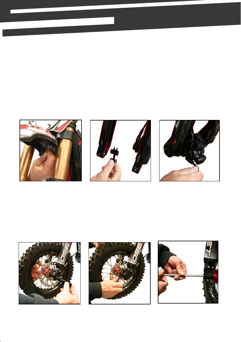
5. Fit front mudguard using the bolt & washers provided (picture 1).
6. Fing Front Wheel.
Remove disk pad spacer (picture 2 - this item is used for transport only, keep this if
you are likely to leave the bike without the front wheel ed).
(1.) (2.) (3.)
7. Loosen top calliper Allen bolts (picture 3 - using 5mm wrench) - so it will move side to
side so as to aid ng of wheel.
8. With one axle bolt already screwed into the axle, hold the front wheel in the fork
lowers & slide the axle in through the hub. (picture 4 - ensure the pinch bolts on the
front of the forks are already loose).
9. Tighten the two pinch bolts on the side of the fork from which you inserted the axle
(picture 5).
(4.) (5.) (6.)
10. Replace locking bolt on the other side of the axle & ghten (picture 6).

12
11. Finally, ghten to remaining two fork pinch bolts on the fork lower.
12. Spin the front wheel and apply the front brake. Do this twice. While holding the front
brake on - ghten calliper bolts. This will centre the calliper and help to give even
wear of the pads and free running of the front wheel.
13. Adjusng rear calliper. Ensure rear wheel is clear of ground and turn by hand and
check brakes are not binding. If they are, loosen cap screws and adjust.
Be aware that because the wheel can be moved back and forth for chain adjustment the
calliper does also - so make sure it does not rub on the outer diameter of disc.
14. Install the front number plate using the supplied ‘zip-es’. This aaches to the
handlebars and the forks (picture 7).
17. Unpack charger (if supplied) from its box and read pages 21-23 of this manual.
Charge the baeries while thoroughly reading the rest of this owners manual.
(7.) Zip-es (8.) (9.)
15. Check re pressure of both res and conrm they are properly inated to 20-40 psi.
Light riders can use lower pressures.
16. The baeries are not connected for shipping purposes and will need connecng. It is
vital that connecons are made correctly. The baery strap should be ed before
connecng the main baery lead. Install the baery as indicated (picture 8 & 9).
18. Compress and check each brake lever in turn. The lever should not compress
completely to the bar. Each individual brake should hold the bike securely when you
push the OSET against the brake. If your brake needs adjustment, follow the
instrucons on page 19. Learning riders should be aware which lever operates which
brake.
19. For maximum baery life, always fully charge before operang your OSET for the rst
me and never store with discharged baeries. (See page 22-23).
20. While your baeries are charging, please Read Your Owners Manual completely.
13
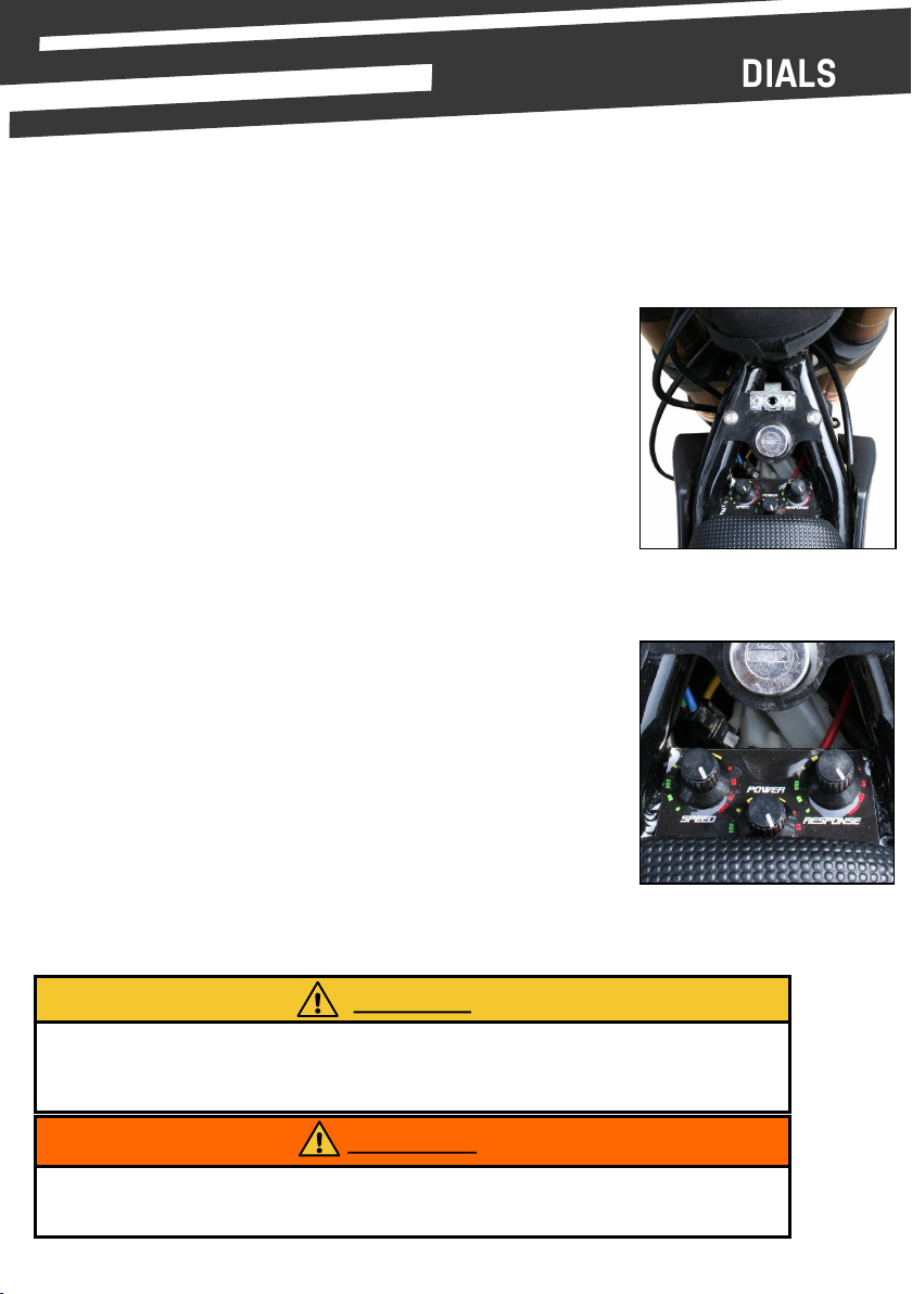
DIAL ADJUSTMENT
THESE DIALS ARE TO BE ADJUSTED BY A RESPONSIBLE ADULT ONLY.
SPEED DIAL
Speed liming device for novice riders
This motorcycle is equipped with a speed liming device to restrict top
speed. Use the device unl the rider becomes familiar with operang
the motorcycle
The speed dial is located underneath the rubber bung for convenience.
This must only be changed by a responsible adult. When dial is turned to
the fully clockwise posion, the bike will have a maximum speed, when
in the an-clockwise posion the speed will be reduced to its minimum.
POWER DIAL
This is the most important adjustability feature on the bike and must
ALWAYS start with the lowest seng, and make changes in very small
increments. It may appear that the highest power will be suitable for an
advanced rider, but it must be understood that there is a lot of power
available.
It is a great feature to have such a range available, but it MUST be
treated with respect. ALWAYS adjust from lower to higher, in very small
increments.
THROTTLE RESPONSE DIAL
It must be treated very carefully as the range of adjustability is
enormous.
The funcon of this dial is to adjust the ‘response’ of the bike. Fully
an-clockwise will give the slowest throle response. Fully clockwise
will give the quickest response.
Always check the dial sengs before the rider gets back on to ensure the desired seng is
correct for the abilies of the rider. The dials are sensive to small adjustments, do not
guess at changes.
CAUTION
Keep clear of all moving parts when checking dial sengs. Failure to do so could result in
serious injury.
WARNING

14
KEY SWITCH
The key switch turns the power on and o. When the rider is sing
on the bike, this is located in front of them above the tank cover.
The key is removable, and should be removed when the bike is not
in use.
KILL SWITCH
This switch is in addion to the key switch and provides extra func-
onality. To enter the on posion place magnec top cap on base.
The key switch MUST be in the ‘on’ posion for the magnec kill
switch to operate.
With the key switch in the ‘on’ posion, the kill switch can be used to
turn the bike on by simply connecng the red magnec cap to the
black base on the handlebar, to turn the bike o using the kill switch
remove the magnec red cap from the black base on the handlebar.
As a safety precauon, if the throle is applied before the kill switch
is connected, the bike will not move.
Always ensure the rider is wearing the kill switch around their wrist
and that the cord is ghtened rmly.
DIAL PANEL REMOVAL
The bike’s adjustment dials are located beneath the small black panel
which also houses the key switch.
To remove the panel, twist the fastener and li the front of the
panel up and towards the handlebars.
The baery charge indicator is located on the throle assembly and
shows the state of the baeries. The indicator lights can be checked
at any me to determine if the main power is o or on. Always turn
the power o and remove the key when the bike is not in use.
NOTE
Now your OSET is fully assembled, adjusted and checked. Once the baeries are fully
charged, your OSET will be ready to ride safely.
CHARGE INDICATOR
15
Your OSET features a tradional chain and sprockets. It is direct drive, with no gears.
With the motor mounted in the swing arm, suspension movement has no eect on tension.
However, the chain does need to be checked and adjusted regularly, especially when the
bike is new.
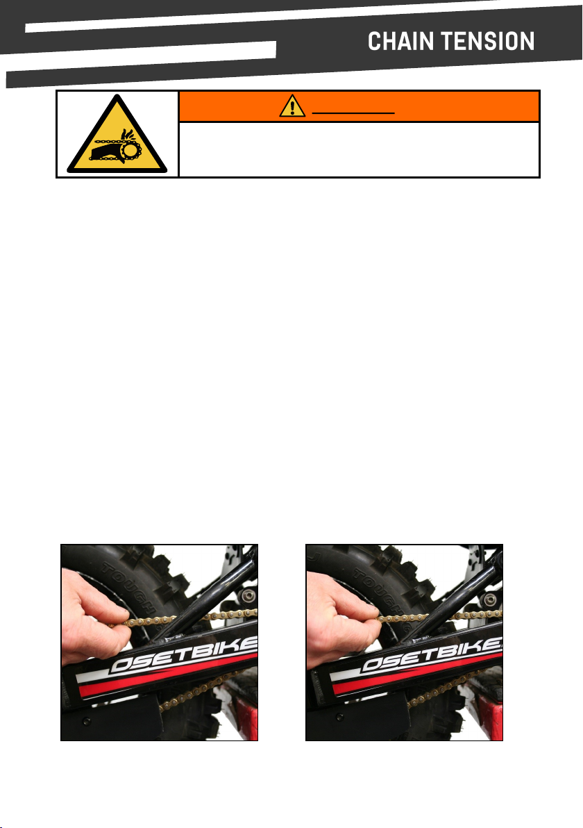
The chain must be checked before every ride and adjusted as necessary. There should be
very lile slack in the chain. Adjustment is done as follows:
1. Ensure power is turned o.
2. Loosen axle nuts (shown opposite).
3. Turn chain tensioner nuts evenly on both sides. Very small movements can make a
big dierence. Do not ghten so much there is no slack at all.
It should be ‘taught’, not ‘ght‘. Rotate wheel by hand and check chain tension.
4. Lubricate the chain & check the sprocket bolts for ghtness.
5. Reverse the above procedure, ensuring all bolts are ght.
6. Check the wheel for alignment and the chain for tension.
These two pictures show the correct tension.
When pushing up on the chain’s ghtest point, it should only move by 5-10mm.
Entanglement Hazard. Turn power o before starng
work.
WARNING
16
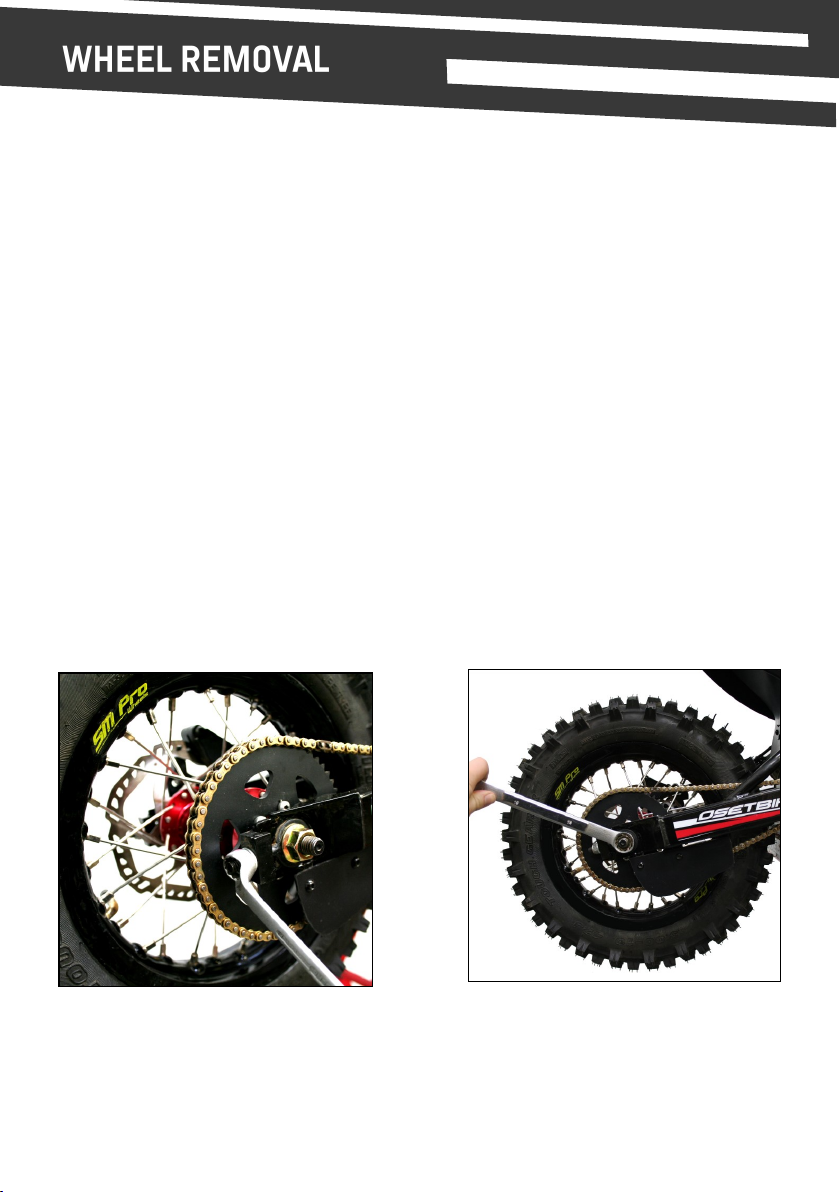
REAR WHEEL INSTALLATION
(2.) Chain tensioner nut (13mm)
1. Ensure power is switched o and the key removed.
2. Li the bike onto a block or stand so the wheels are o the ground.
3. Loosen the axle bolts (see image 1.)
4. Loosen the chain adjustment nuts to the point where the wheel can be pushed forward,
and the chain slipped o to the right of the sprockets (see image 2.)
5. Pull back on the wheel to remove it.
6. To re-install the wheel reverse the above procedures. Ensure the chain is correctly
adjusted and lubricated, the wheel is aligned, and all nuts and bolts are ght
(1.) Axle Nut (19mm)

17
ADJUSTING THE FRAME HEIGHT
The frame of the MX-10 features an overall height adjustment. The procedure to change this
height is outlined below.
1. With the seat unit removed, undo & remove the bolt in the upper shock mount
(see image 1 below).
2. Push up on swing arm unl rear shock mounng hole aligns with desired mounng hole
on the frame.
3. Re-insert shock bolt & ghten nut (see image 2 below).
(1.) (2.)
The padded seat unit of your MX-10 bike is removable, allowing access to some of the bike’s
electrical components. By removing the two screws shown below, the seat can be lied up &
backwards to release from the bike.
(1.) Unscrew & remove seat bolts. (2.) Li seat up & backwards to release.
REMOVING THE SEAT
18
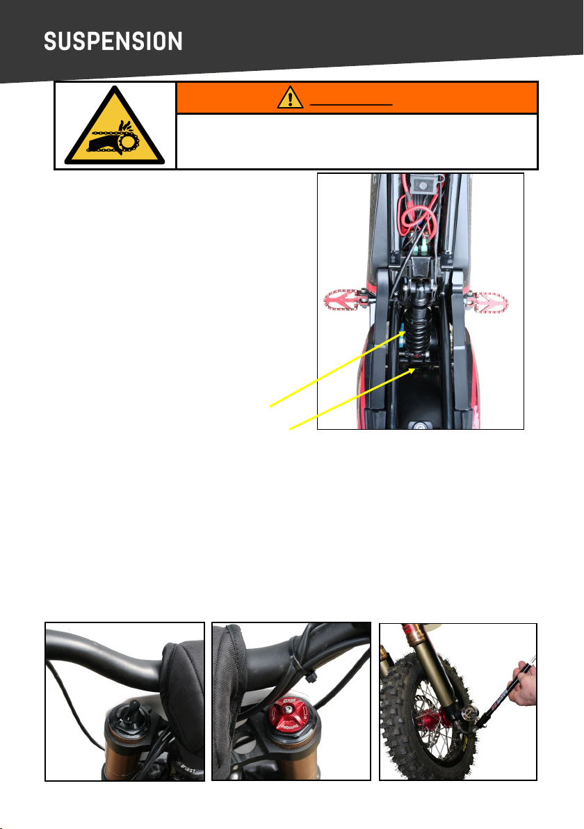
Adjustment ring
Rebound Dial
Please refer to the secon on assembling your OSET bike (page 11) for informaon on
installing the front wheel, and reverse the instrucons for removal.
Your OSET bike is equipped with a single coil
spring type rear shock. For a harder/ser ride
at the rear ghten the adjustment ring in a
clockwise direcon.
For a soer ride, loosen the adjuster by turning
an-clockwise. It also features a very eecve
rebound dial.
Oponal springs are available from your OSET
dealer to adjust the spring rate.
Entanglement Hazard. Turn power o before starng
work.
WARNING
OSET bikes feature adjustable front and rear suspension. The available adjustability is a great
feature. Separate owner’s manuals are provided. Please read for further informaon on how to
best set up the suspension.
The front suspension is an ‘air’ fork. A specic air pump is required to add pressure which can
be purchased from your local OSET dealer. The fork is also adjustable for rebound & preload
via two simple dials located on the top of the fork.
FRONT SUSPENSION FORKS
Preload Dial. Rebound Dial. Suspension Air Pump.
REAR SUSPENSION

19
The brakes are self adjusng to a point, but correct alignment is vital to get the maximum
performance. The pads must be equidistant from the disc for maximum eciency.
Visually inspect the pads as you spin the wheel. Check that alignment is good and pad to disc
distance is even. If adjustments are needed follow the instrucons below:
• Using an Allen wrench, loosen the calliper mounng bolts, allowing the calliper to
move freely from le to right.
• With the bike raised, slowly spin the wheel before pulling the brake lever. This will allow
the calliper to ‘centre’ on the disc.
• With the lever sll holding the pads ghtly on the disc, re-ghten the calliper bolts.
• If the wheel does not spin freely with the brake released and further adjustment is
required beyond the limits of the built in adjustment, the calliper posion itself can be
adjusted further by the use of spacer washers. In this way, the calliper can be lined up
perfectly.
Loosen calliper. Squeeze lever.
Inspect pads. Adjust lever reach.
The brake levers can be adjusted for ‘reach’. Use a small 2mm Allen key.
Turn an-clockwise to bring the reach closer to the bar (for smaller hands).

20
• Ensure power is turned o, and remove the key.
• With the side panel already removed, unscrew & disconnect the power lead (image 4).
• Next, release the baery retaining strap (image 5).
• Finally, carefully li the baery box out of the bike (image 6).
To reinstall baery, reverse the procedure above.
REMOVING THE SIDE PANEL
(1.) Twist fastener (2.) Li side panel clear (3.) Side panel removed
To reinstall the side panel, reverse the procedure above. Ensure fastener is ghtened securely.
BATTERY REMOVAL
(4.) (5.) (6.)
Please Note:
This secon of the user manual only applies to bikes supplied with an ocial OSET lithium
baery pack & charger. For bikes supplied with other baeries, please see the suppliers
instrucons for baery removal & charging.
Table of contents
Other oset Motorcycle manuals


