OSF Pool control PC-400-ES User manual
.
Installation- and Operating Instructions
PC-400-ES
Art. No.: 3002700105
Functioning:
The filter control system PC-400-ES enables time-controlled connection and
disconnection of a 400V A.C. filter pump. Setting of the daytime and the individual response
times can be noted from the corresponding operating instructions of the automatic switch
which is enclosed. By means of the selector switch in the front cover it is possible to:
a)
Switch on and off the functioning of the unit. Attention, the control system is thus not
disconnected from the mains supply at all poles!
b)
to switch the unit to permanent operation or automatic operation (automatic switch) of the
filter pump.
Also during the working time of the filter pump, the heating of the pool is regulated by the
electronic temperature control. During interruptions of the filtering process, the heating is
automatically switched off by the internal locking device. The requested temperature of the
pool water may be chosen or the heating may be switched off by an adjuster on the front
plate.
Operation of the filter pump and the heating is displayed by indicator lamps in the front cover -
controlling is therefore possible at any time.
Connection terminals for an electronic level control -NR-12-TRS-2 or NR-12-TRS-3 ensure
a comfortable automatic control of the water level in the pool. Additionally, the filter pump is
protected against damage which may arise due to operation of the filter unit without water.
Connection terminals for an -EUROTRONIK-10 (Art.No. 3104800201) ensure an
enlargement of the filter control to an automatic filter- and re-flushing control.
Another terminal connection enables the connection of additional devices, e.g. dosing
technology. The terminals D/D are potential-free and can therefore be used individually. The
relay contact between terminals D/D is closed during the filter times; this relay contact is open
outside of the filter times. This contact can be used with a maximum voltage of 230V and a
maximum load of 400W (cos φ = 1).
The connection terminals for the winding protection contact (WSK) enable the connection of a
winding protection contact switch, which is integrated in the motor winding of the filter pump. If
this contact opens, e.g. due to excessive heating of the motor winding, the filter pump and with
it the heating and dosing technology are automatically switched off. As soon as the winding
protection contact closes after the motor winding has cooled down, the units switches on
again automatically. A manual reset is not required. The "WSK" connection terminals carry
230V.
Operation of the filter pump and the heating is displayed by indicator lamps in the front cover -
controlling is therefore possible at any time.
The filter pump is protected against overload by an electronic motor protection (current range
continuously adjustable up to 8A).

Operating manual PC-400-ES page: 2
Technical Data:
Dimensions:
220mm x 220mm x 100mm
Operating voltage:
400V/50Hz
Power consumption of the control system:
abt.1,5VA
Capacity:
Pump:
max. 3,0 kW (AC3)
Heating:
max. 0,4 kW (AC1)
Type of protection:
IP 40
Installation:
The control unit must be mounted such that it is protected from moisture in accordance with its degree of
protection. The ambient temperature must lie between 0°C and + 40°C and should vary as little as possible. The
relative humidity at the installation position must not exceed 95% and there must not be any condensation. Avoid
exposing the unit to direct heat or sunlight.
The swimming pool is to be constructed in such a way that a possible technical defect, a power failure or a
defective control cannot cause any consequential damage.
Electrical connection:
The power supply for the unit must be provided via an all-pole disconnection switch with a minimum contact gap of
3mm and via a residual-current circuit breaker with a fault current IFN ≤30mA.
Always disconnect the unit from the power supply before opening the case. All electrical wiring and calibration and
servicing work must be performed solely by an approved electrician. The attached wiring diagrams and all
applicable safety regulations must be observed.
Low voltage lines:
Low-voltage lines must not be laid along with three-phase or AC power cables in the same cable conduit. In
general, always avoid routing low-voltage lines close to three-phase or AC power cables.
When using a 400V three-phase pump:
When using a 230V AC pump:

Operating manual PC-400-ES page: 3
This control is not suitable for connecting a filter pump with speed control. We have other
controls in our delivery program for such pumps.
The bridge which is installed by the manufacturer between the two terminals designated as Th
has to be removed if a safety temperature limiter is connected. If the latter is not connected,
the bridge has to remain in place.
The bridge which is installed by the manufacturer between the terminals 13 and 14 has to be
removed if a level control unit NR-12-TRS-2 is connected. If a level control unit is not
connected, the bridge has to remain bolted between these terminals. In this case, the
terminals 11 and 12 shall not be used.
The bridge which is installed by the manufacturer between the terminals 5and 3 has to be
removed, if an EUROTRONIK-10 is connected. If an EUROTRONIK-10 is not connected,
the bridge between these terminals has to remain in place. In this case, the terminals 2and 4
shall not be used.
The factory-fitted bridge between the two terminals marked WSK must be removed when
connecting a winding protection contact. If no winding protection contact is available, it must
remain screwed in.
Opening one of the contacts between terminals 13 and 14 or 3 and 5 causes the filter pump,
dosing technology and heating to be switched off immediately.
Closing one of the contacts between terminals 2 and 4 or 11 and 12 forces the filter pump to
be switched on.
The electronic control is protected together with the EUROTRONIK-10, the level control and
the heating by a 3.15A fine-wire fuse inside the device.
Electronic motor protection:
The 3-phase filter pump is protected from
damage resulting from overload by an
electronic motor protection. To do so the motor
protection needs to be set to the nominal
current of the filter pump (see name plate of
the pump). If the nominal current of the filter
pump is not known, the motor protection can
be set using the following procedure:
1. Turn the adjustment screw of the motor
protection in the terminal box clockwise up
to the stop.
2. Switch the pump on
3. Turn the adjustment screw slowly counter
clockwise until the motor protection trips
and the red fault message comes on.
4. Turn the adjustment screw clockwise by
some degrees (approx. 10%).
5. Release the motor protection with the black
key: the fault message goes off and the
filter pump runs.
Adjust motor protection

Operating manual PC-400-ES page: 4
Temperature control:
The electronic temperature control and the
temperature detector have been aligned to
each other at the factory. If the detector is
replaced, a new alignment can be made using
a potentiometer inside the equipment. If, due
to an unsuitable installation position of the
temperature detector, the water temperature
does not match the desired temperature, this
can also be adjusted using the same
potentiometer.
The table below can be used to check the temperature sensor.
Resistance values of the temperature
sensor:
Temperature Resistance
20°C 5800 Ohms
25°C 4600 Ohms
30°C 3700 Ohms
The temperature detector is supplied with a 1.5m cable as standard. If required this can be
extended up to 20m. To rule out interference avoid installing the detector cable in the vicinity
of supply cables.
Since an exact temperature control is only performed when
there is good heat transfer between temperature detector and
swimming pool water, an osf immersion sleeve R 1/2 "
(product code 3200200001) must be installed in the pipe
system.
Adjust temperature sensor

Operating manual PC-400-ES page: 5
Operation of the timer
Setting the time
Setting the switching times
Operating manual PC-400-ES page: 6
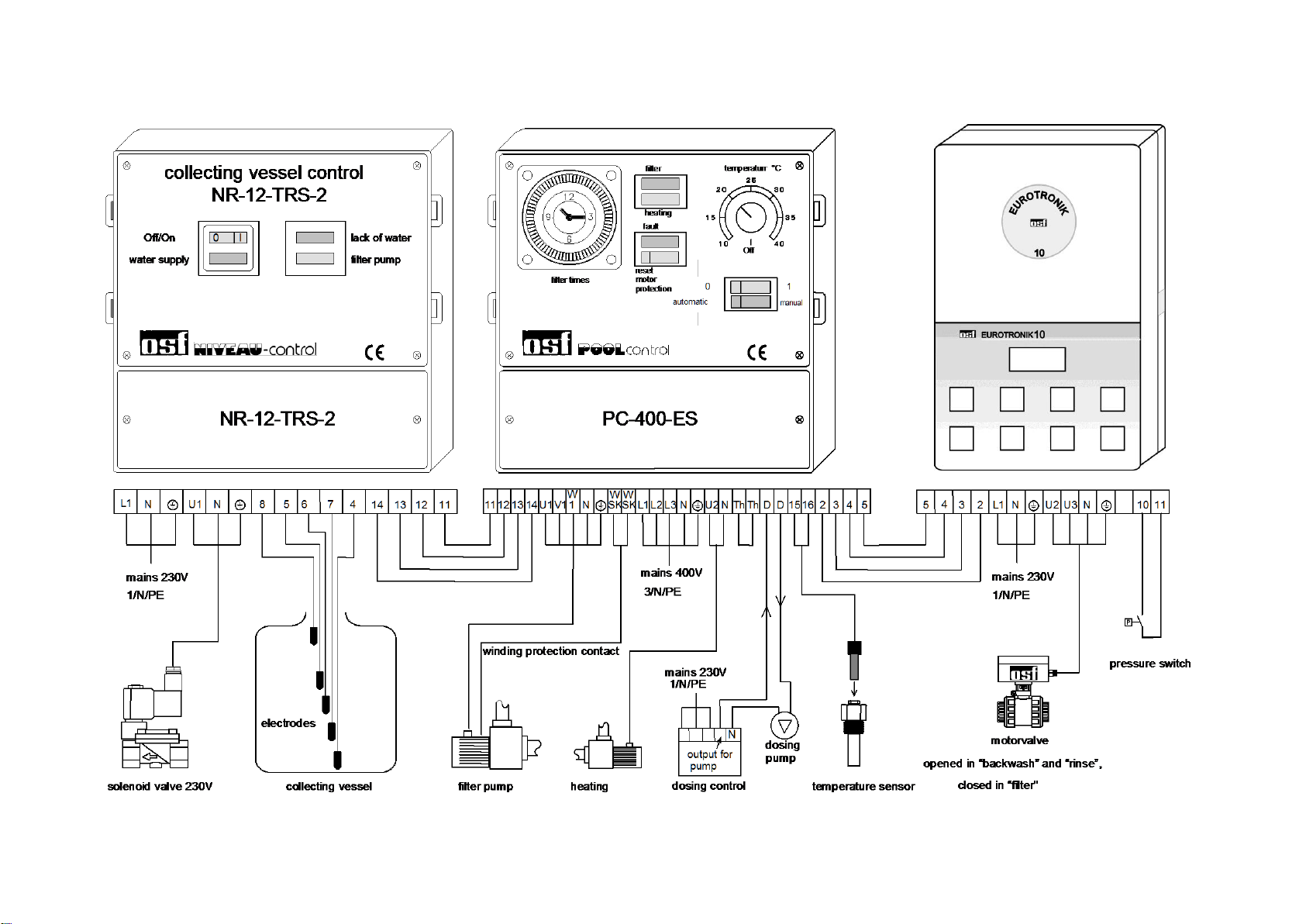
Combination PC-400-ES with NR-12-TRS-2 and Eurotronik-10
Operating manual PC-400-ES page: 7
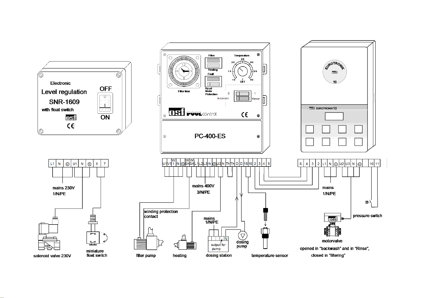
PC-400-ES with SNR-1609 and Eurotronik-10

Operating manual PC-400-ES page: 8
osf Hansjürgen Meier
Elektrotechnik und Elektronik GmbH & Co KG
Eichendorffstraße 6
D-32339 Espelkamp
E-Mail: [email protected]
Internet: www.osf.de
Subject to change without notice! 3/22
Further information can be found on the Internet at the following address::
https://osf.de/download/documents/doclist.php?device=PC-400-ES&subdir=none
This manual suits for next models
1
Table of contents
Other OSF Control System manuals

Popular Control System manuals by other brands

Crestron
Crestron Green Light GL-IPAC-SW8 product manual

Studio Technologies
Studio Technologies 236 user guide

Rowe
Rowe HASCP Operation manual

TSI Instruments
TSI Instruments DICKEY-john INTELLIAG ISO6 Operator's manual

Mitsubishi Electric
Mitsubishi Electric MELDAS 60 Series Programming manual

Hypertherm
Hypertherm ArcGlide THC instruction manual


