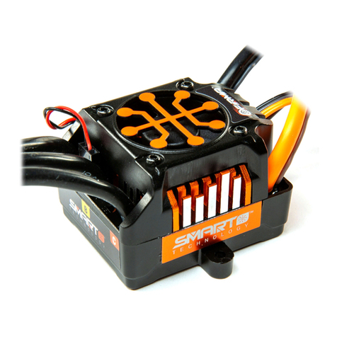
Horizon Hobby Dynamite FU2E User manual

1
Bürstenloser esC mitsensoren im massstaB 1:10
Bedienungsanleitung
Contrôleur éleCtronique de vitesse (esC)
sans Balais aveC Capteur éChelle 1/10
Manuel d’utilisation
esC Brushless Con sensori in sCala 1/10
Manuale di istruzioni
1/10-sCale sensored Brushless esC
instruction Manual

EN
2
Thank you for choosing the Dynamite®brand.
We know that you, the customer, are the reason
we are in business. Your satisfaction is our
number one priority. With this in mind, we have
produced this product to be of the highest quality,
performance and reliability, and at a “value-
packed” price. We hope it provides you with
hours of enjoyment in your next RC project.
Features
• CompatiblewithNi-Cd/Ni-MHandLi-Po/
Li-Ionbatteries.
• Pre-wiredwithbullet-stylemotorconnectors
and a universal receiver plug that fits most
popular radio systems.
• Designedtooperatewithsensored,non-
sensored and brushed motors.
• Programmingallowseasyinterfaceto
change settings from the throttle trigger on
your transmitter or with the use of the Fuze™
programming card.
1/10-Scale Sensored Brushless ESC DYN3780 Instruction Manual
WARNING: Read the ENTIRE
instruction manual to become familiar
with the features of the product before
operating. Failure to operate the product
correctly can result in damage to the
product, personal property and cause
serious injury.
ThisisasophisticatedhobbyproductandNOTa
toy.Itmustbeoperatedwithcautionandcommon
sense and requires some basic mechanical
ability.FailuretooperatethisProductinasafe
and responsible manner could result in injury
or damage to the product or other property.
This product is not intended for use by children
without direct adult supervision. Do not attempt
disassembly, use with incompatible components
or augment product in any way without the
approvalofHorizonHobby,Inc.Thismanual
contains instructions for safety, operation and
maintenance.Itisessentialtoreadandfollowall
the instructions and warnings in the manual, prior
to assembly, setup or use, in order to operate
correctly and avoid damage or serious injury.
CAUTION: This product can become
extremely hot when in use, which could lead
to burns.
NOTICE
All instructions, warranties and other collateral
documents are subject to change at the sole
discretionofHorizonHobby,Inc.Forup-to-
date product literature, visit horizonhobby.com
and click on the support tab for this product.
The following terms are used throughout the
product literature to indicate various levels of
potential harm when operating this product:
NOTICE:Procedures,whichifnotproperly
followed, create a possibility of physical
propertydamageANDalittleornopossibility
of injury.
CAUTION:Procedures,whichifnotproperly
followed, create the probability of physical
propertydamageANDapossibilityofserious
injury.
WARNING:Procedures,whichifnotproperly
followed, create the probability of property
damage, collateral damage, and serious injury
ORcreateahighprobabilityofsupercial
injury.
Meaning of Special Language

EN
3
Mounting the Speed Control
MounttheFuzeESCinthelocationspecied
by your vehicle’s instruction manual. Use the
double-sided foam tape to secure the speed
control in position.
IMPORTANT: Be sure all wiring connections
can be reached prior to mounting.
Use double-sided foam tape to secure the
switch to a convenient location on the chassis
or shock tower.
Specications
Operation ...................Proportionalforward,
proportional reverse with
braking delay
InputVoltage..............6–9cellNi-Cd/Ni-MH
2S–3SLi-Po/Li-Ion
PeakCurrent ..............100A
Continuous Current....70A
BECOutput ................6V
OverloadProtection....Thermal
Dimensions................42mmx37mm
Weight........................120 g
Wiring Diagram –
Sensored Brushless Motors
Cooling fan wire
Sensor wire
Speed Control
Receiver
Brushless
Motor
Motor Battery
Steering
Servo
CH 1
CH 2
Wiring Diagram –
Sensorless Brushless Motors
Cooling fan wire
Speed Control
Receiver
Brushless
Motor
Motor Battery
Steering
Servo
CH 1
CH 2
Wiring Diagram – Brushed
Motors
Cooling fan wire
Speed Control
Receiver
Brushed
Motor
Motor Battery
Steering
Servo
CH 1
CH 2
Center yellow
wire not used
Quick Start Guide
The quick start setup guide will get you running
quicklyusingtheESC’sdefaultsettings.
1. Solderahigh-qualitybatteryconnectortothe
ESC.
2. MounttheESCandmotorintothecar.
3. ConnecttheESCtothemotor.

EN
For sensored brushless motors:
1. ConnectESCterminal“A”(typically
designated by a blue wire) to the motor’s
terminal“A”(typicallydesignatedbyablue
wire).
2. ConnectESCterminal“B”(typically
designated by a yellow wire) to the motor’s
terminal“B”(typicallydesignatedbyayellow
wire).
3. ConnectESCterminal“C”(typically
designated by an orange wire) to the motor’s
terminal“C”(typicallydesignatedbyan
orange wire).
4. Connect the small, 6-wire sensor harness
fromtheESCtothemotor.
For non-sensored brushless motors:
1. ConnectESCterminal“A”(typically
designated by a blue wire) to the motor’s
terminal“A”(redwireonaDynamiteFuze
non-sensored motor).
2. ConnectESCterminal“B”(typically
designated by a yellow wire) to the motor’s
terminal“B”(bluewireonaDynamiteFuze
non-sensored motor).
3. ConnectESCterminal“C”(typically
designated by an orange wire) to the motor’s
terminal“C”(blackwireonaDynamiteFuze
non-sensored motor).
For brushed motors:
1. ConnectESCterminal“A”(typically
designated by a blue wire) to the motor’s
positiveterminal(typicallydesignatedbya
red wire).
2. ConnectESCterminal“C”(typically
designated by an orange wire) to the motor’s
negativeterminal(typicallydesignatedbya
black wire).
3. TheESC’s“B”terminaloryellowwireis
not used in brushed motor applications.
4. PlugintheESCreceiverleadtoCH2onyour
receiver.
5. MakesuretheESC’sswitchisOFF.
6. PlugabatteryintotheESC.
Throttle/System Calibration
Procedure
1. ForproperESCoperation,adjusttransmitter
as follows:
A.SetHIGHATVorEPAtomaximumsetting
[amount of throw at full throttle].
B.SetLOWATV,EPAorATLtomaximum
setting [amount of throw at full brakes].
C.SetEXPONENTIALtozerosetting[throttle
channel linearity].
D.SetTHROTTLECHANNELTRIMtomiddle
setting[adjustsneutralposition/increasesor
decreases coast brakes].
*Notalltransmittershavetheseadjustments*
2. Turn on the transmitter.
3. Whileholdingfullthrottleonyourtransmitter,
turntheESCswitchON.
A. After a few seconds you’ll hear 6 tones
created by the motor.
B. Release the throttle to the neutral position;
after a few seconds you’ll hear 4 tones.
C. Apply full brake position; after a few
seconds you’ll hear 4 tones.
D.TurntheESCswitchoff.
E.TurnontheESCswitch.Afewsecondslater
theESCwillarmwith3risingtonesfollowed
by 4 short tones. You’re ready to go!
CAUTION: Always disconnect
thebatteryfromtheESCwhenyouhave
finished operating your vehicle. The
ESC’sswitchonlycontrolsthepowerto

EN
5
thereceiverandservos.TheESCwill
continue to draw current from the battery
evenwiththeswitchintheOFFposition.
ESC Functions and Modes
TheFuzeESCallowsyoutocustomizetheway
your vehicle performs on the track.
Take your time to familiarize yourself with many
settingssoyouwillbereadytoadjusttheESCfor
changing conditions.
ESC Programming Procedure
Programmingcanbeaccomplishedusingaradio
transmitter or handheld quick programming card
(DYN3745).
Transmitter Controlled Programming
1. Initializesystemcalibration.LeavetheESC
powerONafterstep3-Cofcalibration,
bringingtheESCintothetransmitter
controlled programming mode.
2. The programming sequence will always be
presented in sequential order beginning with
function1(brakemode).Whenusingthe
transmittertosetESCprogramming,youmust
allow the system to walk through to the mode
thatyouintendtochange.Inotherwords,if
youintendtochangeaparameterinMode
8, you must first allow the system to work its
way through all preceding modes sequentially.
Programmingismucheasierandfasterusing
theQuickProgrammingCard.Whenusingthe
QuickProgrammingCard,youcanchangeany
parameter at any time without waiting for the
system to walk through any sequentially
previous modes.
1. Brake Mode
There are 8 available
options in the brake
mode. These allow
you to choose from
0%, 20%, 40%, 60%,
70%, 80%, 90% and
100% brake strength.
Inbrakemode,themotorproduces1beep
signifying brake mode, followed by 1 to 8
beeps signifying the available options:
1 beep–1 beep 0% brake strength
1 beep–2 beeps 20% brake strength
1beep–3beeps 40%brakestrength
1 beep–4 beeps 60% brake strength
1 beep–5 beeps 70% brake strength
1 beep–6 beeps 80% brake strength
1 beep–7 beeps 90% brake strength
1 beep–8 beeps 100% brake strength
(factorydefault)
Oncetheseriesof
beeps for the option
you wish to choose
has completed, move
the throttle position to
maximum and release to
neutral. You will receive
a 4-beep confirmation of
programming.Ifatthis
time you do not wish
to proceed to the next
function, you can simply
shut the power off to
theESC.

EN
2. Drag Brake
Mode
There are 8 available
options in the drag
brake mode. These
allow you to choose
from 0%, 5%, 10%,
15%, 20%, 25%,
30%and80%drag
brake strength.
Indragbrakemode,themotorproduces2
beeps signifying drag brake mode, followed by
1 to 8 beeps signifying the available options:
2 beeps–1 beep 0% drag brake
(factorydefault)
2 beeps–2 beeps 5% drag brake
2beeps–3beeps 10%dragbrake
2 beeps–4 beeps 15% drag brake
2 beeps–5 beeps 20% drag brake
2 beeps–6 beeps 25% drag brake
2beeps–7beeps 30%dragbrake
2 beeps–8 beeps 80% drag brake
Oncetheseriesof
beeps for the option
you wish to choose
has completed, move
the throttle position to
maximum and release to
neutral. You will receive
a 4-beep confirmation of
programming.Ifatthis
time you do not wish
to proceed to the next
function, you can simply
shut the power off to
theESC.
3. Throttle Speed
There are 5 available
options in the throttle
speed sensitivity
mode. They are very
soft, soft, standard,
quick and very quick.
Inthrottlespeedmode,themotorproduces3
beeps signifying throttle speed mode, followed
by 1 to 5 beeps signifying the available
options:
3beeps–1beep verysoftthrottlesensitivity
3beeps–2beeps softthrottlesensitivity
3beeps–3beeps standardthrottlesensitivity
(factorydefault)
3beeps–4beeps quickthrottlesensitivity
3beeps–5beeps veryquickthrottle
sensitivity
4. Start Power
There are 5 available
options in the start
up motor timing
settings. They are very
soft, soft, standard,
powerful and very
powerful. The more
powerful start speeds
offer quick and
powerful motor output
from a complete
stop. This function is
ideal when used for
high or low traction
conditions.
Instartpowermode,themotorproduces4
beeps signifying start power mode, followed
by 1 to 5 beeps signifying the available
options:
4 beeps–1 beep very soft starting power
(factorydefault)
4 beeps–2 beeps soft starting power
4beeps–3beeps standardstartingpower
4 beeps–4 beeps powerful starting power
4 beeps–5 beeps very powerful starting
power

EN
7
5. Reverse Power
There are 8 available
options in the reverse
mode. These allow
you to choose from
0%, 20%, 40%, 60%,
70%, 80%, 90% and
100% reverse power.
Inreversepowermode,themotorproduces5
beeps signifying reverse power mode, followed
by 1 to 8 beeps signifying the available
options:
5 beeps–1 beep 0% reverse power
5 beeps–2 beeps 20% reverse power
5beeps–3beeps 40%reversepower
5 beeps–4 beeps 60% reverse power
(factorydefault)
5 beeps–5 beeps 70% reverse power
5 beeps–6 beeps 80% reverse power
5 beeps–7 beeps 90% reverse power
5 beeps–8 beeps 100% reverse power
Oncetheseriesof
beeps for the option
you wish to choose
has completed, move
the throttle position to
maximum and release to
neutral. You will receive
a 4-beep confirmation of
programming.Ifatthis
time you do not wish
to proceed to the next
function, you can simply
shut the power off to
theESC.
6. Forward/
Reverse
Run Mode
There are 5 different
options in the
forward/reverserun
mode. They are:
forward only, 2 stage
reverse, 2 stage
reverse with safe
brake, reverse with
1-second delay and
reverse with 1-second
delay and safe brake.
Inforward/reverserunmode,themotor
produces 6 beeps signifying reverse power
mode, followed by 1 to 5 beeps signifying
the available options:
6 beeps–1 beep forward only with brake
6 beeps–2 beeps forward, brake and 2-stage
reverse
6beeps–3beeps forward,brake,2-stage
reverse,safebrake(factory
default)
6 beeps–4 beeps forward, brake, reverse
with 1 sec. delay
6 beeps–5 beeps forward, brake, reverse
with 1 sec. delay, safe brake

EN
8
More about the Battery
Management System/Low
Voltage Cutoff
The low-voltage cutoff is based on the type of
battery,batteryvoltage,cellcount(forLi-Po/
Li-ionmodes,whichtheESCrecognizesatpower
up) and battery voltage under load. The low-
voltage cutoff occurs in 2 steps.
Step1:Themotor’spowerisreducedinorderto
alert the user that the battery is about to reach the
cutoff point.
Step2:Oncethebatteryreachesthelow-voltage
cutoff point, the motor will shut down completely.
Inordertoprotectyourbattery,donotresume
operation.Shutthevehicleoffandinstalla
fully charged battery.
The following will show the low-voltage
cutoff levels:
7. Motor Timing
There are 4 options
available in this
function that allow you
to adjust motor timing
to maximize your
motor’s performance.
The options are: auto,
low, standard and
advanced. Advanced
timing offers
maximum power
output at the expense
of efficiency and run
time.
Inmotortimingmode,themotorproduces7
beeps signifying motor timing mode, followed
by 1 to 4 beeps signifying the available
options:
7 beeps–1 beep auto motor timing
(factorydefault)
7 beeps–2 beeps low motor timing
7beeps–3beeps standardmotortiming
7 beeps–4 beeps advanced motor timing
Oncetheseriesof
beeps for the option
you wish to choose
has completed, move
the throttle position to
maximum and release to
neutral. You will receive
a 4-beep confirmation of
programming.Ifatthis
time you do not wish
to proceed to the next
function, you can simply
shut the power off to
theESC.
8. Battery
Management
System/Low
Voltage Cutoff
The battery
management sytem
allows you to protect
your batteries from
damage due to over-
discharge.Sixtotal
options are available;
3forLi-Po/Li-Ion
batteriesand3forNi-
Cd/Ni-MHbatteries.
Inbatterymanagementsystemmode,the
motor produces 8 beeps signifying battery
management system mode, followed by 1 to 6
beeps signifying the available options:
8beeps–1beep Ni-Cd/Ni-MH4.5Vcutoff
(factorydefault)
8beeps–2beeps Ni-Cd/Ni-MH4.2Vcutoff
8beeps–3beeps Ni-Cd/Ni-MH3.9Vcutoff
8beeps–4beeps Li-Po/Li-Ionlightdischarge
8beeps–5beeps Li-Po/Li-Ionstandard
discharge
8beeps–6beeps Li-Po/Li-Ionheavy
discharge

EN
9
8beeps–2beeps Ni-Cd/Ni-MH4.2Vcutoff
8beeps–3beeps Ni-Cd/Ni-MH3.9Vcutoff
8beeps–4beeps Li-Po/Li-Ionlightdischarge
Step1:3.2Vpercell
Step2:2.9Vpercell
8beeps–5beeps Li-Po/Li-Ionstandard
discharge
Step1:2.9Vpercell
Step2:2.6Vpercell
8beeps–6beeps Li-Po/Li-Ionheavydischarge
Step1:2.6Vpercell
Step2:2.3Vpercell
Programming Using the
Quick Programming Card
TheeasiestwaytoprogramyourFuzeESCisby
using theHandheldQuickProgrammingCard
(DYN3745).
UsingtheQuickProgrammingCardallowsyou
to go directly into the mode setting that you wish
to change without waiting through any of the
functions that precede it.
1. RemovetheESCreceiverleadfromthe
receiver and connect it to the programming
card. Be sure to observe correct polarity.
2. ConnectabatterytotheESC.
3. TurnontheESC.Youwillhear6beeps
followed by one rising tone. You have now
entered into programming mode.
4. Using the black buttons on the front of the
card,enterthefunctionnumber(listedon
the front of the card) followed by the option
number(listedonthebackofthecard)that
you wish to choose. For example, if you wish
to adjust the brake strength to 80% and drag
brake to 10%: press button #1 followed by
button #6. After about 1 second you will hear
1 long tone followed by 6 beeps confirming
theprogrammingsetting.Nextyouwillhear
1 rising tone, which allows you to enter the
nextsetting.Pressbutton#2followedby
button#3.Afterabout1secondyouwillhear
2longtonesfollowedby3beepsconrming
theprogrammingsetting.Onceagainyou
will hear 1 rising tone. You can either enter
into another function for modification or
simplyturnoffthepowertotheESC
to end programming.
5. DisconnecttheESCreceiverleadfromthe
programming card.
6. ConnecttheESCreceiverleadtothereceiver.
CAUTION:ThermalProtection
System:TheFuzeESChasabuilt-inthermal
overloadtoprotecttheESCfromhigh
operating temperatures and is not user-
programmable.IftheESCreaches248°F
(120°C),theESCwillshutdownuntilitcan
cool to an acceptable operating temperature.
Ifthermalshutdownsoccuroften,changeto
a smaller pinion gear size or a motor with a
lower Kv rating. An additional cooling fan
(DYN3746)isavailabletoreduce
operating temperatures.

EN
10
Troubleshooting Guide
Symptom Solution
Steeringservo
operates
but the motor does
not run
Programmingisnotcomplete.
ReprogramtheESCbyfollowingtheprogramminginstructions.
Speedcontrolconnectedtoreceiverincorrectly.
Refer to manufacturer’s instructions.
Motordefective.Testmotorindependently,repairorreplaceasneeded.
Lowbatteries.Chargeasneeded.
Check motor connections.
Steeringandmotor
do not function Receiver wired incorrectly. Check polarity and orientation of control plugs.
Radioinoperational.Seeradioinstructionmanual.
Batteries discharged. Recharge or replace.
Full speed not
attainable Battery has reached the programmed low-voltage cutoff.
Transmitteradjustedimproperly.Seeradioinstructionsforproperadjustment.
ESCprogrammedincorrectly.Reprogram.
Motorslowsbut
will not stop Throttletrimmaybesetimproperly.Seeradioinstructionmanual.
ESCprogramdoesnotmatchtransmitter.ReprogramESC.
Reduced radio
range/Interference Transmitter antenna is not fully extended.
Motorcapacitorsbroken/missing.Repairorreplace.(Brushedmotorsonly)
Motornoise.MovereceiverfurtherawayfromESC,motorandwiring.
Transmitter batteries low. Replace batteries.
Interferencetransmittedonornearradiofrequency.Movetoadifferent
locationand/orchangeradiochannels(seemanufacturer’sinstructions).

EN
11
LIMITED WARRANTY
What this Warranty Covers
HorizonHobby,Inc.(“Horizon”)warrantstothe
originalpurchaserthattheproductpurchased(the
“Product”)willbefreefromdefectsinmaterials
and workmanship at the date of purchase.
What is Not Covered
This warranty is not transferable and does
notcover(i)cosmeticdamage,(ii)damage
duetoactsofGod,accident,misuse,abuse,
negligence, commercial use, or due to improper
use,installation,operationormaintenance,(iii)
modicationofortoanypartoftheProduct,(iv)
attemptedservicebyanyoneotherthanaHorizon
Hobbyauthorizedservicecenter,or(v)Products
notpurchasedfromanauthorizedHorizondealer.
OTHERTHANTHEEXPRESSWARRANTY
ABOVE,HORIZONMAKESNOOTHER
WARRANTYORREPRESENTATION,AND
HEREBYDISCLAIMSANYANDALLIMPLIED
WARRANTIES,INCLUDING,WITHOUT
LIMITATION,THEIMPLIEDWARRANTIESOF
NON-INFRINGEMENT,MERCHANTABILITY
ANDFITNESSFORAPARTICULARPURPOSE.
THEPURCHASERACKNOWLEDGESTHAT
THEYALONEHAVEDETERMINEDTHAT
THEPRODUCTWILLSUITABLYMEETTHE
REQUIREMENTSOFTHEPURCHASER’S
INTENDEDUSE.
Purchaser’s Remedy
Horizon’ssoleobligationandpurchaser’ssole
andexclusiveremedyshallbethatHorizonwill,
atitsoption,either(i)service,or(ii)replace,any
ProductdeterminedbyHorizontobedefective.
Horizonreservestherighttoinspectanyand
allProduct(s)involvedinawarrantyclaim.
Serviceorreplacementdecisionsareatthe
solediscretionofHorizon.Proofofpurchaseis
requiredforallwarrantyclaims.SERVICEOR
REPLACEMENTASPROVIDEDUNDERTHIS
WARRANTYISTHEPURCHASER’SSOLEAND
EXCLUSIVEREMEDY.
Limitation of Liability
HORIZONSHALLNOTBELIABLEFORSPECIAL,
INDIRECT,INCIDENTALORCONSEQUENTIAL
DAMAGES,LOSSOFPROFITSORPRODUCTION
ORCOMMERCIALLOSSINANYWAY,
REGARDLESSOFWHETHERSUCHCLAIM
ISBASEDINCONTRACT,WARRANTY,TORT,
NEGLIGENCE,STRICTLIABILITYORANYOTHER
THEORYOFLIABILITY,EVENIFHORIZONHAS
BEENADVISEDOFTHEPOSSIBILITYOFSUCH
DAMAGES.Further,innoeventshalltheliability
ofHorizonexceedtheindividualpriceofthe
Productonwhichliabilityisasserted.AsHorizon
has no control over use, setup, final assembly,
modification or misuse, no liability shall be
assumed nor accepted for any resulting damage
or injury. By the act of use, setup or assembly, the
useracceptsallresultingliability.Ifyouasthe
purchaser or user are not prepared to accept the
liabilityassociatedwiththeuseoftheProduct,
purchaserisadvisedtoreturntheProduct
immediately in new and unused condition to the
place of purchase.
Law
ThesetermsaregovernedbyIllinoislaw(without
regard to conflict of law principals). This
warranty gives you specific legal rights, and you
may also have other rights which vary from state
tostate.Horizonreservestherighttochangeor
modify this warranty at any time without notice.
WARRANTY SERVICES
Questions, Assistance, and Services
Yourlocalhobbystoreand/orplaceofpurchase
cannotprovidewarrantysupportorservice.Once
assembly,setuporuseoftheProducthasbeen
started, you must contact your local distributor
orHorizondirectly.ThiswillenableHorizonto
better answer your questions and service you
in the event that you may need any assistance.

EN
12
For questions or assistance, please direct your
email to productsupport@horizonhobby.com, or
call877.504.0233tollfreetospeaktoaProduct
Supportrepresentative.Youmayalsond
information on our website at www.horizonhobby.
com.
Inspection or Services
IfthisProductneedstobeinspectedorserviced,
pleaseusetheHorizonOnlineServiceRequest
submission process found on our website or
callHorizontoobtainaReturnMerchandise
Authorization(RMA)number.PacktheProduct
securelyusingashippingcarton.Pleasenote
that original boxes may be included, but are not
designed to withstand the rigors of shipping
withoutadditionalprotection.Shipviaacarrier
that provides tracking and insurance for lost or
damagedparcels,asHorizonisnotresponsible
for merchandise until it arrives and is accepted
atourfacility.AnOnlineServiceRequestis
availableathttp://www.horizonhobby.comunder
theSupporttab.Ifyoudonothaveinternet
access,pleasecontactHorizonProductSupport
toobtainaRMAnumberalongwithinstructions
for submitting your product for service. When
callingHorizon,youwillbeaskedtoprovideyour
complete name, street address, email address
and phone number where you can be reached
during business hours. When sending product
intoHorizon,pleaseincludeyourRMAnumber,a
list of the included items, and a brief summary of
the problem. A copy of your original sales receipt
must be included for warranty consideration. Be
sureyourname,address,andRMAnumber
are clearly written on the outside of the
shipping carton.
NOTICE: Do not ship Li-Po batteries to
Horizon. If you have any issue with a Li-Po
battery, please contact the appropriate
Horizon Product Support office.
Warranty Requirements
For Warranty consideration, you must
include your original sales receipt
verifying the proof-of-purchase date.
Providedwarrantyconditionshavebeenmet,
yourProductwillbeservicedorreplacedfreeof
charge.Serviceorreplacementdecisionsareat
thesolediscretionofHorizon.
Non-Warranty Service
Should your service not be covered
by warranty service will be completed
and payment will be required without
notification or estimate of the expense
unless the expense exceeds 50% of the
retail purchase cost. By submitting the item
for service you are agreeing to payment of the
servicewithoutnotication.Serviceestimates
are available upon request. You must include
this request with your item submitted for service.
Non-warrantyserviceestimateswillbebilled
aminimumof½houroflabor.Inaddition
youwillbebilledforreturnfreight.Horizon
accepts money orders and cashiers checks, as
wellasVisa,MasterCard,AmericanExpress,
and Discover cards. By submitting any item to
Horizonforservice,youareagreeingtoHorizon’s
Terms and Conditions found on our website
http://www.horizonhobby.com/Service/Request/.

EN
13
StevenA.Hall
VicePresident
InternationalOperationsandRiskManagement
HorizonHobby,Inc.
Country of Purchase Horizon Hobby Address Phone Number/ Email
UnitedStates
HorizonServiceCenter
(Electronicsand
engines)
4105 Fieldstone Rd
Champaign,Illinois
61822USA
877-504-0233
OnlineRepairRequestvisit
www.horizonhobby.com/service
HorizonProductSupport
(Allotherproducts)
4105 Fieldstone Rd
Champaign,Illinois
61822USA
877-504-0233
productsupport@horizonhobby.com
United Kingdom HorizonHobbyLimited Units1-4PloytersRd
StapleTye,Harlow,Essex
CM187NS
United Kingdom
+44(0)1279641097
sales@horizonhobby.co.uk
Germany HorizonTechnischer
Service
Christian-Junge-Straße1
25337Elmshorn
Germany
+49(0)41212655100
service@horizonhobby.de
France HorizonHobbySAS 14RueGustaveEiffel
Zoned’ActivitéduRéveilMatin
91230Montgeron
+33(0)160474470
infofrance@horizonhobby.com
Compliance Information for the European Union
Declaration of Conformity
(inaccordancewithISO/IEC17050-1)
No.HH2009102201
Product(s): DYN1/10thBrushlessESC,
DYN1/18MiniBrushlessESC
ItemNumber(s): DYN3741,DYN3740
Equipmentclass: 1
The object of declaration described above is
in conformity with the requirements of the
specifications listed below, following the
provisionsoftheEuropeanEMCDirective
2004/108/EC:
EN55022 Radiodisturbance
characteristics
EN55024 Immunitycharacteristics
EN61000-4-2 Electrostaticdischarge
immunity test
Signedforandonbehalfof:
HorizonHobby,Inc.
Champaign,ILUSA
Oct22,2009
Instructions for Disposal
of WEEE by Users in the
European Union
This product must not be disposed of with other
waste.Instead,itistheuser’sresponsibilityto
dispose of their waste equipment by handing
it over to a designated collection point for the
recycling of waste electrical and electronic
equipment. The separate collection and recycling
of your waste equipment at the time of disposal
will help to conserve natural resources and
ensure that it is recycled in a manner that protects
human health and the environment. For more
information about where you can drop off your
waste equipment for recycling, please contact
your local city office, your household waste
disposal service or where you purchased
the product.

DE
14
WARNUNG: Lesen Sie die GESAMTE
Bedienungsanleitung durch, um sich vor
der Inbetriebnahme mit den Funktionen
des Produkts vertraut zu machen. Wird
dieses Produkt nicht korrekt betrieben,
kann dies zu Schäden am Produkt oder
anderen Sachschäden und zu schweren
Verletzungen führen.
Dies ist ein hochentwickeltes Hobbyprodukt
und KEIN Spielzeug. Es muss mit Vorsicht und
gesundem Menschenverstand betrieben werden
und erfordert gewisse technische Grundfähigkeiten.
Wird dieses Produkt nicht auf eine sichere und
verantwortungsvolle Weise betrieben, kann dies
zu Verletzungen oder Schäden am Produkt oder
anderen Sachwerten führen. Dieses Produkt
eignet sich nicht für die Verwendung durch Kinder
ohne direkte Überwachung eines Erwachsenen.
Versuchen Sie nicht ohne Genehmigung durch
Horizon Hobby, Inc., das Produkt zu zerlegen,
es mit inkompatiblen Komponenten zu verwenden
oder auf jegliche Weise zu erweitern. Diese
Bedienungsanleitung enthält Anweisungen für
Sicherheit, Betrieb und Wartung. Es ist unbedingt
notwendig, vor Zusammenbau, Einrichtung oder
Verwendung alle Anweisungen und Warnhinweise
im Handbuch zu lesen und zu befolgen, damit das
Produkt bestimmungsgemäß betrieben werden
kann und Schäden oder schwere Verletzungen
vermieden werden.
ACHTUNG: Dieses Produkt kann
beim Gebrauch extrem heiß werden, was zu
Verbrennungen führen kann.
HINWEIS
Alle Anweisungen, Garantien und anderen
zugehörigen Dokumente können im eigenen
Ermessen von Horizon Hobby, Inc. jederzeit
geändert werden. Die aktuelle Produktliteratur
finden Sie auf horizonhobby.com unter
der Registerkarte „Support“ für das
betreffende Produkt.
Die folgenden Begriffe werden in der
gesamten Produktliteratur verwendet, um auf
unterschiedlich hohe Gefahrenrisiken beim
Betrieb dieses Produkts hinzuweisen:
HINWEIS: Wenn diese Verfahren nicht korrekt
befolgt werden, können sich möglicherweise
Sachschäden UND eine geringe oder keine
Gefahr von Verletzungen ergeben.
ACHTUNG: Wenn diese Verfahren nicht korrekt
befolgt werden, ergeben sich wahrscheinlich
Sachschäden UND die Gefahr von schweren
Verletzungen.
WARNUNG: Wenn diese Verfahren nicht
korrekt befolgt werden, ergeben sich
wahrscheinlich Sachschäden, Kollateralschäden
und schwere Verletzungen ODER mit hoher
Wahrscheinlichkeit oberflächliche Verletzungen.
Spezielle Bedeutungen

DE
15
Spezikationen
Betrieb Proportional vorwärts,
proportional rückwärts mit
Bremsverzögerung
Eingangsspannung 6 bis 9 Zellen Ni-Cd/Ni-MH
2S bis 3S Li-Po/Li-Ion
Spitzenstrom 100A
Dauerstrom 70A
BEC-Ausgang 6V
Überlastschutz Thermisch
Abmessungen 42mm x 37mm
Gewicht 120g
Schaltplan –
Bürstenlose Motoren mit
Sensoren
Cooling fan wire
Sensor wire
Speed Control
Receiver
Brushless
Motor
Motor Battery
Steering
Servo
CH 1
CH 2
Bürstenloser ESC mit Sensoren
im Maßstab 1:10 DYN3780 -
Bedienungsanleitung
Vielen Dank, dass Sie sich für die Marke
Dynamite®entschieden haben. Wir wissen, dass
wir ohne Sie, den Kunden, nicht im Geschäft
wären. Ihre Zufriedenheit hat bei uns höchste
Priorität. Deshalb haben wird dieses Produkt so
hergestellt, dass es höchste Qualität, Leistung
und Zuverlässigkeit zu einem günstigen Preis
bietet. Wir sind sicher, dass Sie damit viele
Stunden lang Freude an Ihrem nächsten RC-
Projekt haben werden.
Merkmale
• KompatibelmitNi-Cd/Ni-MH-undLi-Po/
Li-Ion-Akkus.
• VorverdrahtetmitBullet-
Motoranschlusssteckern und einem
universellen Empfängerstecker, der auf die
meisten verbreiteten Funksysteme passt.
• AusgelegtaufdenBetriebmitMotorenmit
oder ohne Sensoren oder mit Bürsten.
• Programmierungübereinebenutzerfreundliche
Oberfläche zur Änderung der Einstellungen vom
Gasgeber an Ihren Sender oder mit der Fuze™-
Programmierkarte.
Einbau des ESC
Bauen Sie den Fuze ESC an der Position ein, die
in der Bedienungsanleitung zu Ihrem Fahrzeug
angegeben ist. Befestigen Sie den ESC mit
doppelseitigem Schaumstoffklebeband.
WICHTIG: Stellen Sie vor dem Einbau sicher,
dass alle Anschlussstellen zugänglich sind.
Befestigen Sie den Schalter mit doppelseitigem
Schaumstoffklebeband an einer günstigen Stelle
am Fahrwerk oder an der Stoßdämpferbrücke.

DE
16
Schaltplan – Bürstenlose
Motoren ohne Sensoren
Cooling fan wire
Speed Control
Receiver
Brushless
Motor
Motor Battery
Steering
Servo
CH 1
CH 2
Schaltplan – Bürstenmotoren
Cooling fan wire
Speed Control
Receiver
Brushed
Motor
Motor Battery
Steering
Servo
CH 1
CH 2
Center yellow
wire not used
Kurzanleitung zum Schnellstart
Mit dieser Kurzanleitung können Sie den Betrieb
schnell aufnehmen, da die Standardeinstellungen
des ESC übernommen werden.
1. Löten Sie einen qualitativ hochwertigen
Akkuanschluss am ESC an.
2. Bauen Sie den ESC und den Motor in das
Fahrzeug ein.
3. Schließen Sie den ESC an den Motor an.
Für bürstenlose Motoren mit Sensoren:
1. Schließen Sie den ESC-Anschluss „A“
(normalerweise durch einen blauen Draht
gekennzeichnet) an den Motoranschluss „A“
(normalerweise durch einen blauen Draht
gekennzeichnet) an.
2. Schließen Sie den ESC-Anschluss „B“
(normalerweise durch einen gelben Draht
gekennzeichnet) an den Motoranschluss „B“
(normalerweise durch einen gelben Draht
gekennzeichnet) an.
3. Schließen Sie den ESC-Anschluss „C“
(normalerweise durch einen orangefarbenen
Draht gekennzeichnet) an den Motoranschluss
„C“ (normalerweise durch einen
orangefarbenen Draht gekennzeichnet) an.
4. Schließen Sie den kleinen, 6-drahtigen
Sensorkabelbaum vom ESC an den Motor an.
Für bürstenlose Motoren ohne Sensoren:
1. Schließen Sie den ESC-Anschluss
„A“ (normalerweise durch einen
blauen Draht gekennzeichnet) an den
Motoranschluss „A“ (roter Draht an einem
Dynamite-Fuze-Motor ohne Sensoren) an.
2. Schließen Sie den ESC-Anschluss „B“
(normalerweise durch einen gelben Draht
gekennzeichnet) an den Motoranschluss „B“
(blauer Draht an einem Dynamite-Fuze-Motor
ohne Sensoren) an.
3. Schließen Sie den ESC-Anschluss „C“
(normalerweise durch einen orangefarbenen
Draht gekennzeichnet) an den Motoranschluss
„C“ (schwarzer Draht an einem Dynamite-
Fuze-Motor ohne Sensoren) an.
Für Bürstenmotoren:
1. Schließen Sie den ESC-Anschluss „A“
(normalerweise durch einen blauen
Draht gekennzeichnet) an den positiven
Motoranschluss (normalerweise durch einen
roten Draht gekennzeichnet) an.
2. Schließen Sie den ESC-Anschluss „C“
(normalerweise durch einen orangefarbenen
Draht gekennzeichnet) an den negativen

DE
17
Motoranschluss (normalerweise durch einen
schwarzen Draht gekennzeichnet) an.
3. Für Bürstenmotoren wird der ESC-Anschluss
„B“ oder der gelbe Draht nicht verwendet.
4. Schließen Sie das ESC-Empfängerkabel an
Kanal2 an Ihrem Empfänger an.
5. Stellen Sie sicher, dass der ESC ausgeschaltet
ist.
6. Schließen Sie einen Akku an den ESC an.
Gasgeber/System-Kalibrierung
1. Passen Sie den Sender folgendermaßen
an, um einen korrekten Betrieb des ESC zu
ermöglichen:
A. Stellen Sie HIGH ATV oder EPA auf die
höchste Einstellung [Ausschlag bei Vollgas].
B. Stellen Sie LOW ATV, EPA oder ATL auf
die höchste Einstellung [Ausschlag bei
Vollbremsung].
C. Stellen Sie EXPONENTIAL auf Null
[Linearität des Gaskanals].
D. Stellen Sie THROTTLE CHANNEL
TRIM auf die mittlere Einstellung [passt
neutrale Position an / erhöht oder senkt
Leerlaufbremse].
*Diese Einstellungen sind nicht bei allen
Sendern vorhanden*
2. Schalten Sie den Sender ein.
3. Halten Sie den Sender in Vollgasstellung, und
schalten Sie den ESC-Schalter EIN.
A. Nach ein paar Sekunden gibt der Motor
6Töne von sich.
B. Lassen Sie den Gasgeber los, so dass er
in die neutrale Position zurückkehrt; nach ein
paar Sekunden hören Sie 4Töne.
C. Stellen Sie die Position für eine
Vollbremsung ein; nach ein paar Sekunden
hören Sie 6Töne.
D. Schalten Sie den ESC-Schalter aus.
E. Schalten Sie den ESC-Schalter ein. Nach
ein paar Sekunden schaltet sich der ESC mit
4 aufsteigenden Tönen gefolgt von 4 kurzen
Tönen scharf. Sie sind nun bereit!
ACHTUNG: Trennen Sie stets den Akku
vom ESC, wenn Sie nicht mehr mit dem
Fahrzeug fahren möchten. Der ESC-Schalter
steuert nur den Stromfluss an den Empfänger
und die Servos. Der ESC zieht Strom vom
Akku, auch wenn der Schalter ausgeschaltet ist.
ESC-Funktionen und Modi
Mit dem Fuze ESC können Sie die Performance
Ihres Fahrzeugs auf der Strecke individuell
anpassen.
Nehmen Sie sich Zeit, um sich mit den zahlreichen
Einstellungen vertraut zu machen; dann wissen
Sie, wie Sie den ESC anpassen, wenn sich die
Bedingungen ändern.
ESC-Programmierung
Die Programmierung kann mit einem Funksender
oder mit einer Handheld-Schnellprogrammierkarte
(DYN3745) vorgenommen werden.
Programmierung mit einem Sender
1. Beginnen Sie die Systemkalibrierung. Lassen
Sie den ESC nach Schritt3-C der Kalibrierung
eingeschaltet; dadurch gelangt der ESC in den
sendergesteuerten Programmiermodus.
2. Die Programmiersequenz wird stets in
der angegebenen Reihenfolge angeboten,
beginnend mit Funktion 1 (Bremsmodus).
Wenn Sie den ESC mit dem Sender
programmieren, müssen Sie dem System
erlauben, die Modi nacheinander zu
durchlaufen, bis Sie bei dem Modus angelangt
sind, den Sie ändern möchten. Wenn Sie
beispielsweise einen Parameter in Modus8
ändern möchten, muss das System zunächst
nacheinander alle Modi davor durchlaufen.
Mit der Schnellprogrammierkarte ist die
Programmierung wesentlich einfacher und
schneller. Mit der Schnellprogrammierkarte
können Sie jederzeit jeden Parameter ändern,
ohne dass das System alle früheren Modi
durchgehen muss.

DE
18
1. Bremsmodus
Im Bremsmodus sind
8 Optionen verfügbar.
Sie haben die Wahl
zwischen 0%, 20%,
40%, 60%, 70%,
80%, 90% und
100% Bremsstärke.
Im Bremsmodus gibt der Motor 1Signalton für
den Bremsmodus von sich, gefolgt von 1 bis 8
Tönen für die verfügbaren Optionen:
1Ton – 1Ton 0% Bremsstärke
1Ton – 2Töne 20% Bremsstärke
1Ton – 3Töne 40% Bremsstärke
1Ton – 4Töne 60% Bremsstärke
1Ton – 5Töne 70% Bremsstärke
1Ton – 6Töne 80% Bremsstärke
1Ton – 7Töne 90% Bremsstärke
1Ton – 8Töne 100% Bremsstärke
(Werkeinstellung)
Wenn die Tonfolge für
die gewünschte Option
ertönt ist, bewegen Sie
den Gasgeber auf die
Maximalstellung und
lassen ihn dann wieder
zur Neutralstellung
zurückkehren.
Die Programmierung
wird mit 4Signaltönen
bestätigt. Wenn Sie
keine weitere Funktion
einstellen möchten,
können Sie den ESC
einfach ausschalten.
2. Leerlauf-
bremsmodus
Im Leerlaufbrem-
smodus sind 8
Optionen verfügbar.
Sie haben die Wahl
zwischen 0%, 5%,
10%, 15%, 20%, 25%,
30% und 80% Leerlauf-
bremsstärke.
Im Leerlaufbremsmodus gibt der Motor
2Signaltöne für den Leerlaufbremsmodus
von sich, gefolgt von 1 bis 8Tönen für die
verfügbaren Optionen:
2Töne – 1Ton 0% Leerlaufbremse
(Werkeinstellung)
2Töne – 2Töne 5% Leerlaufbremse
2Töne – 3Töne 10% Leerlaufbremse
2Töne – 4Töne 15% Leerlaufbremse
2Töne – 5Töne 20% Leerlaufbremse
2Töne – 6Töne 25% Leerlaufbremse
2Töne – 7Töne 30% Leerlaufbremse
2Töne – 8Töne 80% Leerlaufbremse

DE
19
1. Bremsmodus
Im Bremsmodus sind
8 Optionen verfügbar.
Sie haben die Wahl
zwischen 0%, 20%,
40%, 60%, 70%,
80%, 90% und
100% Bremsstärke.
Im Bremsmodus gibt der Motor 1Signalton für
den Bremsmodus von sich, gefolgt von 1 bis 8
Tönen für die verfügbaren Optionen:
1Ton – 1Ton 0% Bremsstärke
1Ton – 2Töne 20% Bremsstärke
1Ton – 3Töne 40% Bremsstärke
1Ton – 4Töne 60% Bremsstärke
1Ton – 5Töne 70% Bremsstärke
1Ton – 6Töne 80% Bremsstärke
1Ton – 7Töne 90% Bremsstärke
1Ton – 8Töne 100% Bremsstärke
(Werkeinstellung)
Wenn die Tonfolge für
die gewünschte Option
ertönt ist, bewegen Sie
den Gasgeber auf die
Maximalstellung und
lassen ihn dann wieder
zur Neutralstellung
zurückkehren.
Die Programmierung
wird mit 4Signaltönen
bestätigt. Wenn Sie
keine weitere Funktion
einstellen möchten,
können Sie den ESC
einfach ausschalten.
2. Leerlauf-
bremsmodus
Im Leerlaufbrem-
smodus sind 8
Optionen verfügbar.
Sie haben die Wahl
zwischen 0%, 5%,
10%, 15%, 20%, 25%,
30% und 80% Leerlauf-
bremsstärke.
Im Leerlaufbremsmodus gibt der Motor
2Signaltöne für den Leerlaufbremsmodus
von sich, gefolgt von 1 bis 8Tönen für die
verfügbaren Optionen:
2Töne – 1Ton 0% Leerlaufbremse
(Werkeinstellung)
2Töne – 2Töne 5% Leerlaufbremse
2Töne – 3Töne 10% Leerlaufbremse
2Töne – 4Töne 15% Leerlaufbremse
2Töne – 5Töne 20% Leerlaufbremse
2Töne – 6Töne 25% Leerlaufbremse
2Töne – 7Töne 30% Leerlaufbremse
2Töne – 8Töne 80% Leerlaufbremse
3. Gasgebergesch-
windigkeit
Im Modus für die
Gasgebergeschwind-
igkeit sind 5 Optionen
verfügbar: Sehr sanft,
sanft, normal, schnell
und sehr schnell.
Im Modus für die Gasgebergeschwindigkeit
gibt der Motor 3Signaltöne für den
Gasgebergesch-windigkeits-Modus von sich,
gefolgt von 1 bis 5Tönen für die verfügbaren
Optionen:
3 Töne – 1 Ton sehr sanfte
Gasgeberempfindlichkeit
3 Töne – 2 Töne sanfte
Gasgeberempfindlichkeit
3 Töne – 3 Töne normale
Gasgeberempfindlichkeit
(Werkeinstellung)
3 Töne – 4 Töne schnelle
Gasgeberempfindlichkeit
3 Töne – 5 Töne sehr schnelle
Gasgeberempfindlichkeit
Wenn die Tonfolge für
die gewünschte Option
ertönt ist, bewegen Sie
den Gasgeber auf die
Maximalstellung und
lassen ihn dann wieder
zur Neutralstellung
zurückkehren.
Die Programmierung
wird mit 4Signaltönen
bestätigt. Wenn Sie
keine weitere Funktion
einstellen möchten,
können Sie den ESC
einfach ausschalten.
4. Startleistung
Im Modus für die
Startmotorleistung
sind 5 Optionen
verfügbar: Sehr sanft,
sanft, normal, stark
und sehr stark. Die
leistungsstärkeren
Startgeschwindig-
keiten bieten eine
schnelle und starke
Motor-beschleunigung
vom voll-ständigen
Stillstand. Diese
Funktion eignet sich
ideal zum Fahren bei
hoher oder niedriger
Bodenhaftung.
Im Startleistungsmodus gibt der Motor
4Signaltöne für den Startleistungsmodus
von sich, gefolgt von 1 bis 5Tönen für die
verfügbaren Optionen:
4Töne – 1Ton sehr sanfte Startleistung
(Werkeinstellung)
4Töne – 2Töne sanfte Startleistung
4Töne – 3Töne normale Startleistung
4Töne – 4Töne starke Startleistung
4Töne – 5Töne sehr starke Startleistung

DE
20
5. Leistung im
Rückwärtsgang
Im Rückwärtsgang-
modus sind 8
Optionen verfügbar.
Sie haben die Wahl
zwischen 0%, 20%,
40%, 60%, 70%,
80%, 90% und 100%
Rückwärtsgang-
leistung.
Im Rückwärtsgang-Leistungsmodus gibt der
Motor 5Signaltöne für den Rückwärtsgang-
Leistungsmodus von sich, gefolgt von 1 bis
8Tönen für die verfügbaren Optionen:
5Töne – 1Ton 0% Leistung im
Rückwärtsgang
5Töne – 2Töne 20% Leistung im
Rückwärtsgang
5Töne – 3Töne 40% Leistung im
Rückwärtsgang
5Töne – 4Töne 60% Leistung im
Rückwärtsgang
(Werkeinstellung)
5Töne – 5Töne 70% Leistung im
Rückwärtsgang
5Töne – 6Töne 80% Leistung im
Rückwärtsgang
5Töne – 7Töne 90% Leistung im
Rückwärtsgang
5Töne – 8Töne 100% Leistung im
Rückwärtsgang
Wenn die Tonfolge für
die gewünschte Option
ertönt ist, bewegen Sie
den Gasgeber auf die
Maximalstellung und
lassen ihn dann wieder
zur Neutralstellung
zurückkehren.
Die Programmierung
wird mit 4Signaltönen
bestätigt. Wenn Sie
keine weitere Funktion
einstellen möchten,
können Sie den ESC
einfach ausschalten.
6. Vorwärts/
Rückwärts-
Laufmodus
Im Vorwärts/Rückwärts-
Laufmodus sind 5
Optionen verfügbar.
Sie haben die Wahl
zwischen nur vorwärts,
rückwärts in 2Stufen,
rückwärts in 2Stufen
mit Sicherheitsbremse,
rückwärts mit 1Sekunde
Verzögerung und
rückwärts mit 1Sekunde
Verzögerung und
Sicherheitsbremse.
Im Vorwärts/Rückwärts-Laufmodus gibt
der Motor 6 Signaltöne für den Vorwärts/
Rückwärts-Laufmodus von sich, gefolgt von 1
bis 5Tönen für die verfügbaren Optionen:
6Töne – 1Ton nur vorwärts mit Bremse
6Töne – 2Töne vorwärts, Bremse und
2Stufen rückwärts
6Töne – 3Töne vorwärts, Bremse,
2Stufen rückwärts und
Sicherheitsbremse
(Werkeinstellung)
6Töne – 4Töne vorwärts, Bremse,
rückwärts mit 1Sek.
Verzögerung
6Töne – 5Töne vorwärts, Bremse, rückwärts
mit 1Sek. Verzögerung,
Sicherheitsbremse
Table of contents
Languages:
Other Horizon Hobby Control System manuals