Sel SEL-411L-2 User manual

Schweitzer Engineering Laboratories, Inc. SEL-411L-2 Data Sheet
Line Current Differential Protection
Automation and Control System With
Sampled Values or TiDL Technology
Key Features and Benefits
The SEL-411L-2 Advanced Line Differential Protection, Automation and Control System With Sampled Values (SV) or
Time-Domain Link (TiDL)®Technology combines high-speed line current differential, distance, and directional protec-
tion with complete bay control.
➤Line Current Differential Protection. The 87L function of the SEL-411L-2 provides protection for any transmission
line or cable with as many as three terminals over serial communications and as many as four terminals over
Ethernet communications, in three-pole or single-pole tripping modes. Each terminal can be connected in a dual
breaker arrangement.
➤Generalized Alpha Plane. Phase-segregated (87LP), negative-sequence (87LQ), and zero-sequence (87LG)
differential elements use patented generalized alpha plane comparators. Combined with overcurrent supervision,
external fault detection, optional charging current compensation, and disturbance detection logic, these provide the
87L function with exceptional security and sensitivity. An adaptive feature increases security of the 87L function if:
➢An external fault is detected
➢Communications synchronization is degraded
➢Charging current compensation is enabled but momentarily impossible because of loss-of-potential (LOP) or
other conditions
The generalized alpha plane principle is similar to the two-terminal SEL-311L. However, the SEL-311L and
SEL-411L-2 are two completely independent hardware and firmware platforms. They are not compatible to be
applied in a line-current differential scheme.
➤Inclusion of Power Transformers in the Protective Zone. The SEL-411L-2 allows for in-line power transformer
applications by compensating for transformer vector group, ratio, and zero-sequence current. The 87L function
supports both harmonic blocking and/or harmonic restraint for stabilization during transformer inrush conditions.
During over-excitation conditions, the SEL-411L-2 uses fifth-harmonic current to secure the 87L elements. The
87L function can protect multiwinding transformers.
SEL-411L-2 Advanced Line Differential
Protection, Automation, and Control System

SEL-411L-2 Data Sheet Schweitzer Engineering Laboratories, Inc.
2
➤Charging Current Compensation. Line charging current compensation enhances sensitivity of the 87L elements
in applications for protection of long, extra high voltage lines or cables. Charging current is calculated by using the
measured line terminal voltages and is then subtracted from the measured phase current. This compensation
method results in accurate compensation for both faulted and non-faulted system conditions. The line charging
current algorithm has built-in fallback logic in the event of an LOP condition.
➤External Fault Detector. An external fault detection algorithm secures the 87L elements against CT errors when
the algorithm detects one of the two following conditions:
➢An increase in the through current of the protected zone that is not accompanied by an increase in the
differential current of the protected zone (typical of an external fault)
➢The dc component of any current exceeds a preset threshold compared with the ac component without the
differential current having a significant change (typical when energizing a line reactor or a power transformer)
➤Stub Bus Protection. Disconnect status inputs and voltage elements can enable high-speed stub bus protection
and proper response toward remote SEL-411L-2 relays. Stub bus protection in the SEL-411L-2 provides a true
restrained differential function that yields exceptional security in dual-breaker applications.
➤87L Communications Protocols Supported. The SEL-411L-2 allows serial 87L communication over direct
point-to-point fiber, IEEE C37.94 multiplexed fiber, EIA-422, and G.703 media.
➤Data Synchronization. The relay allows for synchronizing data exchanged between relays based on the channel (for
symmetrical channels) or using external time sources for applications over Ethernet or asymmetrical channels.
Selecting the synchronization method is on a per-channel basis. If you use external time sources, the SEL-411L-2
provides built-in fallback logic to deal with any loss or degradation of such sources.
➤Broken Conductor Detection (BCD). The optional BCD function can detect a broken conductor over the length of
the protected line to help mitigate possible fire or public hazard. The BCD element is designed for multiterminal
overhead or hybrid lines, including tapped line configurations to detect a conductor break before it converts into a
shunt fault.
➤Complete Distance Protection. You can apply as many as five zones of phase and ground distance and directional
overcurrent elements. Select mho or quadrilateral characteristics for any phase or ground distance element. Use the
optional high-speed distance elements and series-compensation logic to optimize protection for critical lines. Patented
coupling capacitor voltage transformer (CCVT) transient overreach logic enhances the security of Zone 1 distance
elements. Best Choice Ground Directional Element®logic optimizes directional element performance and
eliminates the need for many directional settings. Apply the distance and directional elements in communications-
based protection schemes, such as POTT, DCB, and DCUB, or for instantaneous or time-step backup protection.
➤Power Swing Blocking and Out-of-Step Tripping. You can select power swing blocking of distance elements for
stable power swings or out-of-step tripping for unstable power swings. A zero-setting, out-of-step detection logic is
available, eliminating the need for settings and extensive power system studies.
➤Synchronism Check. Synchronism check can prevent circuit breakers from closing if the corresponding phases
across the open circuit breaker are excessively out of phase, magnitude, or frequency. The synchronism-check
function has a user-selectable synchronizing voltage source and incorporates slip frequency, two levels of maximum
angle difference, and breaker close time into the closing decision.
➤Reclosing Control. You can incorporate programmable single-pole or three-pole trip and reclose of one or two
breakers into an integrated substation control system. Synchronism and voltage checks from multiple sources
provide complete bay control.
➤Advanced Multiterminal Fault Locator. Utilities can efficiently dispatch line crews to quickly isolate line problems
and restore service faster. For two-terminal lines, data are used from each terminal to achieve highly accurate fault
location with an impedance-based fault location estimate. For three-terminal lines, the relay accurately locates
faults by using data from each terminal to compute a three-terminal impedance-based fault location estimate and
correctly identifies a faulted line segment. Upon loss of communication or degraded data synchronization, the relay
returns to a single-ended method, always providing valuable fault location results to aid inspection and repair. The
SEL-411L-2 displays the best available impedance-based fault location estimates for each fault.
➤Dual CT Input. For breaker-and-a-half, ring-bus, or double-bus double-breaker bus applications, the SEL-411L-2
provides proper security for the 87L function by supporting two current inputs for individual measurements of
each breaker. Through the use of SELOGIC®control equations, you can dynamically include or exclude each current
input from the differential zone. With this capability, you can use the SEL-411L-2 in such advanced applications
as breaker substitution in double-bus single-breaker or transfer bus configurations.

Schweitzer Engineering Laboratories, Inc. SEL-411L-2 Data Sheet
3
➤Primary Potential Redundancy. Multiple voltage inputs to the relay provide primary voltage input redundancy.
Upon loss-of-protection (LOP) detection, the relay can use inputs from an electrically equivalent source connected
to the relay.
➤Comprehensive Metering. The built-in, high-accuracy metering functions can improve feeder loading. Use watt
and VAR measurements to optimize feeder operation. Use differential metering to access remote terminal current
values. Minimize equipment needs with full metering capabilities, including rms, maximum/minimum, demand/peak,
energy, and instantaneous values.
➤Bay Control. The relay provides bay control functionality with status indication and control for disconnect switches.
The relay features control for as many as two breakers and status indication of as many as three breakers. Numerous
predefined user-selectable mimic displays are available; the selected mimic appears on the front-panel screen in
one-line diagram format. The one-line diagram includes user-configurable labels for disconnect switches, breakers,
bay name, and display for as many as six analog quantities. The relay features SELOGIC programmable local control
supervision of breaker and disconnect switch operations.
➤Breaker Failure. High-speed (less than one cycle) open-pole detection logic reduces coordination times for critical
breaker failure applications. Apply the relay to supply breaker failure protection for all supported breakers. Logic
for breaker failure retrip and initiation of transfer tripping is included.
➤IEC 60255-149 Compliant Thermal Model. The relay can provide a configurable thermal model for the protection
of a wide variety of devices. This function can activate a control action or issue an alarm or trip when equipment
overheats as a result of adverse operation conditions. A separate resistance temperature detector (RTD) module is
required for this application.
➤Ethernet Access. The optional Ethernet card grants access to all relay functions. Use IEC 61850 Manufacturing
Message Specification (MMS) or DNP3 protocol directly to interconnect with automation systems. You can also
connect to DNP3 networks through a communications processor. Use File Transfer Protocol (FTP) for high-speed data
collection. Connect to substation or corporate LANs to transmit synchrophasors by using TCP or UDP internet protocols.
➤Serial Data Communication. The relay can communicate serial data through SEL ASCII, SEL Fast Message,
SEL Fast Operate, MIRRORED BITS®, and DNP3 protocols. Synchrophasor data are provided in either SEL Fast
Message or IEEE C37.118 format.
➤Automation. The enhanced automation features include programmable elements for local control, remote control,
protection latching, and automation latching. Local metering on the large front-panel LCD eliminates the need for
separate panel meters. Serial and Ethernet links efficiently transmit key information, including metering data, protection
element and control I/O status, synchrophasor data, IEC 61850 Edition 2 GOOSE messages, Sequential Events
Recorder (SER) reports, breaker monitoring, relay summary event reports, and time synchronization. Apply expanded
SELOGIC®control equations with math and comparison functions in control applications. Incorporate as many as
1000 lines of automation logic to accelerate and improve control actions.
➤Synchrophasors. You can make informed load dispatch decisions based on actual real-time phasor measurements
from relays across your power system. Record streaming synchrophasor data from the relay for system-wide disturbance
recording. Control the power system by using local and remote synchrophasor data.
➤Breaker and Battery Monitoring. You can schedule breaker maintenance when accumulated breaker duty
(independently monitored for each pole) indicates possible excess contact wear. The relay records electrical and
mechanical operating times for both the last operation and the average of operations since function reset. Alarm
contacts provide notification of substation battery voltage problems (as many as two independent battery monitors
in some SEL-400 series relays) even if voltage is low only during trip or close operations.
➤Digital Secondary Systems (DSS) Technologies. You can order the relay as either an SV subscriber relay or a
TiDL relay. DSS capable relays receive current and voltage information that is published by remote merging units
instead of standard PT and CT inputs. DSS technologies reduce copper cable lengths and associated installation
labor costs and improve the overall safety of the substation.
➤IEC 61850-9-2LE SV Relay. The SV subscriber relay can subscribe to current and voltage information that is
published by as many as seven remote SV merging units that are compliant with the IEC 61850-9-2LE guideline.
➤TiDL Relay. The TiDL relay can receive current and voltage information from as many as eight SEL-TMUs (TiDL
Merging Units) over direct point-to-point fiber-optic connections. The TiDL relay automatically synchronizes data
collection, alleviating the need or impact of an external clock on protection.
➤Selective Protection Disabling. The subscriber or TiDL relay provides selective disabling of protection functions
by using hard-coded logic or available torque-control equations in case of a loss of communications between your
merging unit and relay that results in the loss of relevant analog data.

SEL-411L-2 Data Sheet Schweitzer Engineering Laboratories, Inc.
4
➤Current Summation. The relay can combine multiple SV stream currents to simplify external wiring.
➤Six Independent Settings Groups. The relay includes group logic to adjust settings for different operating conditions,
such as station maintenance, seasonal operations, emergency contingencies, loading, source changes, and adjacent
relay settings changes. Select the active group settings by control input, command, or other programmable conditions.
➤Software-Invertible Polarities. Inverting individual or grouped CT and PT polarities allows you to account for
field wiring or zones of protection changes. CEV files and all metering and protection logic use the inverted polarities,
whereas COMTRADE event reports do not use inverted polarities but rather record signals as applied to the relay.
➤Parallel Redundancy Protocol (PRP). PRP provides seamless recovery from any single Ethernet network failure.
The Ethernet network and all traffic are fully duplicated with both copies operating in parallel.
➤IEC 61850 Operating Modes. The relay supports IEC 61850 standard operating modes such as Test, Blocked,
On, and Off.
➤IEEE 1588, Precision Time Protocol (PTP). PTP provides high-accuracy timing over an Ethernet network.
➤Digital Relay-to-Relay Communications. MIRRORED BITS communications can monitor internal element conditions
between bays within a station, or between stations, using SEL fiber-optic transceivers. Send digital, analog, and
virtual terminal data over the same MIRRORED BITS channel.
➤Sequential Events Recorder (SER). The SER records the last 1000 events, including setting changes, startups,
and selectable logic elements.
➤Oscillography and Event Reporting. The relay records voltages, currents, and internal logic points at a sampling
rate as fast as 8 kHz. Offline phasor and harmonic-analysis features allow investigation of bay and system performance.
Time-tag binary COMTRADE event reports with high-accuracy time stamping for accuracy better than 10 s.
➤Digitally Signed Upgrades. The relay supports upgrading the relay firmware with a digitally signed upgrade file.
The digitally signed portion of the upgrade file helps ensure firmware and device authenticity after it is sent over a
serial or Ethernet connection.
➤Increased Security. The relay divides control and settings into seven relay access levels; the relay has separate
breaker, protection, automation, and output access levels, among others. Set unique passwords for each access level.
➤Rules-Based Settings Editor. You can communicate with and set the relay by using an ASCII terminal or use
Grid Configurator to configure the relay and analyze fault records with relay element response. Use as many as
200 aliases to rename any digital or analog quantity in the relay.

Schweitzer Engineering Laboratories, Inc. SEL-411L-2 Data Sheet
5
Functional Overview
SV
The SEL-411L-2 SV Subscriber subscribes to
IEC 61850-9-2LE data streams that are published by
merging units, such as the SEL-421-7 Protection, Auto-
mation, and Control System With SV or SEL-401 Pro-
tection, Automation, and Control Merging Unit. The
SEL-421-7 provides full backup protection while the
SEL-401 can provide basic directional overcurrent and
breaker failure protection in the absence of IEC 61850
communications. Using the process bus, the SEL-421-7
SV Publisher or SEL-401 can provide voltage and cur-
rent information to multiple relays that subscribe to SV.
The data may be synchronized via IRIG-B time input or
IEEE 1588-2008 PTP.
TiDL
The SEL-411L-2 TiDL receives and automatically syn-
chronizes data streams from connected and commis-
sioned SEL-TMUs. The TiDL technology does not
require an external time source for local relay protection
functions.
Figure 1 Functional Overview
ENV
21
25
50BF
5150
50BF
5150
67 68
79
81
SEL-411L-2
27 59
87
Connection to
Remote Relay
4
EIA-232
1
IRIG-B
2
Differential
Channel
2*
32
DSS Inputs
Process Bus
2
Ethernet
1
Station Bus
Mapped BK1
Currents
Mapped 52A1
Statuses
Mapped 52A2
Statuses
Mapped
Voltages
Mapped BK2
Currents
Four-port Ethernet card ordering option depicted.
ANSI NUMBERS/ACRONYMS AND FUNCTIONS
21 Phase and Ground Distance
25 Synchronism Check
27 Undervoltage
32 Directional Power
49 IEC 60255-Compliant Thermal Model
50 Overcurrent
(Phase, Zero-Sequence, and Negative-Sequence)
50BF Dual Breaker Failure Overcurrent
51 Time-Overcurrent
(Phase, Zero-Sequence, and Negative-Sequence)
59 Overvoltage
67 Directional Overcurrent
68 Out-of-Step Block/Trip
79 Single-and Three-Pole Reclosing
81 Over- and Underfrequency
87 Current Differential
ADDITIONAL FUNCTIONS
16 SEC Access Security (Serial, Ethernet)
85 RIO SEL MIRRORED BITS Communications
BCD Broken Conductor Detection
BRM Breaker Wear Monitor
DFR Event Reports
ENV SEL-2600 RTD Module*
LGC Expanded SELOGIC Control Equations
LOC Fault Locator
MET High-Accuracy Metering
PMU Synchrophasors
RTU Remote Terminal Unit
SBM Station Battery Monitor
SER Sequential Events Recorder
1 Copper or Fiber Optic
2 Serial or Ethernet (Ethernet coming soon)
* Optional Feature
16
S
E
C
PMU
SERSBM SIP
BCD
ENVDFR
BRM
LGC
LOC MET
Figure 2 SV Network
Process Bus
q
qTime synchronization
is required for SV
communications. Time
synchronization can be
done over a process
bus or station bus
Figure 3 SEL TiDL System
T-Protocol

SEL-411L-2 Data Sheet Schweitzer Engineering Laboratories, Inc.
6
Protection Features
The SEL-411L-2 contains all the necessary protective elements and control logic to protect overhead transmission lines
and underground cables (see Figure 4).
Complete Current Differential
Protection
The SEL-411L-2 differential elements compare phase,
negative-sequence, and zero-sequence components from
each line terminal, as Figure 4 illustrates.
The differential protection in the SEL-411L-2 compares
the vector ratio of the equivalent local and remote cur-
rents in a complex plane, known as the alpha plane, as
Figure 5 shows. For load and external faults with no CT
or communication errors, the vector ratio of remote cur-
rent to local current is –1 or 1180º. The SEL-411L-2
restraint region surrounds the ideal external fault and
load current point, allowing for errors in both magnitude
and phase angle. CT saturation, channel asymmetry, and
other effects during faults outside the protected zone pro-
duce shifts in the magnitude and angle of the ratio. The
characteristic provides proper restraint for these condi-
tions while still providing good sensitivity for high resis-
tance faults with its negative- and zero-sequence
differential elements. You can adjust both the angular
extent and the radial reach of the restraint region.
The differential protection algorithms offer great security
against CT saturation effects. In addition to providing
individual breaker currents to the differential element,
the relay incorporates ultra-fast external fault detection to
cope with fast and severe CT saturation resulting from
high fault currents. It also provides a standing dc detec-
tion algorithm to cope with slower saturation resulting
from large and slowly decaying dc offset in the trans-
former inrush or fault currents under large X/R ratios.
Such provisions prevent the SEL-411L-2 from tripping
on through faults and allows relaxation of CT require-
ments for current differential applications.
The SEL-411L allows single-pole tripping from the 87L
elements. This includes tripping highly resistive faults
from the sensitive 87LQ and 87LG elements. These
87LQ and 87LG elements do not have inherent faulted-
phase identification capabilities. Therefore, the 87L
function incorporates its own faulted-phase selection
logic and uses symmetrical components in the phase dif-
ferential currents to provide very sensitive, accurate, and
fast fault-type identification. Figure 6 shows the operate
times for the 87L elements.
When performing single-pole tripping without differen-
tial enabled or available, the SEL-411L uses a proven
single-ended fault identification logic based on the angu-
lar relationships in the local current.
Figure 4 Differential Element Operate and Restraint Regions
Differential Operate
Phase Currents and Other 87L Data
Differential
Restraint
Differential
Restraint
SV Merging Unit
Figure 5 Operate and Restraint Regions in Alpha Plane
Responses to System Conditions
Internal Faults
Synchronism
Errors
CT Saturation
Internal Faults
With Infeed or
Outfeed
Re(k)
–1
Restraint
Operate
Im(k)

Schweitzer Engineering Laboratories, Inc. SEL-411L-2 Data Sheet
7
Two-Breaker Bays and
Multiterminal Lines
The SEL-411L-2 can accommodate lines terminated as
dual-breaker connections or multiterminal lines. The
SEL-411L-2 supports as many as three terminal applica-
tions over serial communications. The relays measure and
use all of the current inputs and calculate an equivalent
two-terminal alpha plane current. The relays use a pat-
ented method to develop a remote and local current for an
equivalent two terminal system. The equivalent local and
remote currents are applied to the tried and true alpha
plane comparator. As a result, the SEL-411L-2 extends
the advantages of alpha plane implementation to dual-
breaker multiterminal lines.
Line Charging Current Compensation
The SEL-411L-2 compensates for line charging current
by estimating an instantaneous value of the total line
charging current on a per-phase basis and then subtracting
this value from the measured differential current. The
relay uses instantaneous values of the line voltage and
the susceptance of the line (cable) to calculate charging
current in real time on a sample-by-sample basis.
This method is accurate under steady state and transient
conditions. These latter conditions can include external
faults, internal faults, switching events, and line energi-
zation, even with uneven breaker pole operation. Com-
pensating the phase currents removes the charging current
from the sequence currents automatically and improves
the sensitivity of the sequence 87L elements.
Each SEL-411L-2 terminal with access to voltage uses
the lump parameter model of the transmission line and
the local terminal voltage to calculate the total charging cur-
rent:
The relay subtracts a portion of the total charging current
proportional to the number of compensating terminals
from the local phase current. For example, with two relays
compensating for the charging current, each subtracts
half of the total charging current.
By subtracting the total charging current from the differ-
ential signal prior to using the generalized alpha plane
algorithm, the relay moves the operating point to the ideal
blocking point (1180°) when no internal fault conditions
exist. This allows more sensitive settings, particularly for
the 87LP element.
A loss of voltage at one of the line terminals causes the
scheme to use remaining voltages, with properly adjusted
multipliers, for compensation, resulting in removal of the
total line charging current. If no compensation is possi-
ble, the fallback logic engages more secure settings to
retain security of protection.
External Fault Detection
An external fault detection algorithm analyzes particular
characteristics of the 87L zone currents to identify exter-
nal events as a fault, load pickup under exceptionally high
X/R ratio, or a transformer inrush condition that could
jeopardize 87L security with possible subsequent CT sat-
uration. Assertion of the algorithm occurs before and regard-
less of CT saturation, bringing proper security to the 87L
scheme, particularly to the 87LQ and 87LG elements.
The external fault detection algorithm consists of two paths:
➤The ac saturation path guards against potentially
fast and severe CT saturation resulting from high
current magnitudes such as those occurring during
close-in external faults.
➤The dc saturation path guards against typically
slower and less severe saturation that can result
from relatively large and long-lasting dc
component in current signals as can exist during
transformer inrush or slowly cleared external faults
under large X/R ratios.
Figure 6 Operating Time Curves
0.6
0.8
1
1.2
1.4
1.6
1.8
0.6
0.7
0.8
0.9
1
1.1
1.2
1.3
1.4
1.5
1.6
1 2 4 8
Minimum Trip Time
Trip Time (Cycles)
Per Unit Differential Current
87LP
87LQ
87LG
Average Trip Time
Trip Time (Cycles)
87LP
87LQ
87LG
Per Unit Differential Current
201510 1 2 4 8 201510
iCHARGE CLINE
dv
dt
------
•=

SEL-411L-2 Data Sheet Schweitzer Engineering Laboratories, Inc.
8
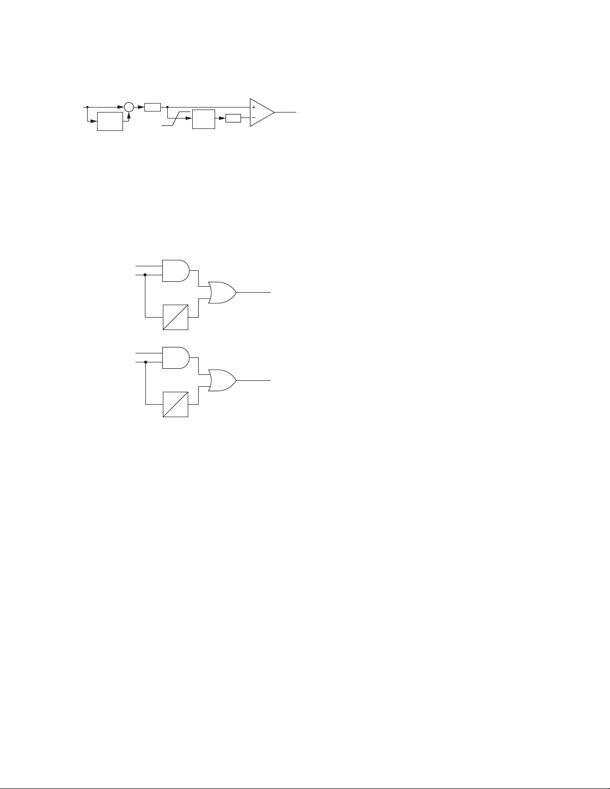
The principle of operation for ac saturation is based on
the observation that all CTs of the differential zone per-
form adequately for a short time into the fault. If so, the
differential current does not develop during the external
faults, but the restraint current increases. This external
fault pattern differs from the internal fault pattern in that
both the differential and restraint currents develop simul-
taneously. The algorithm monitors the difference by respond-
ing to changes in the instantaneous differential current
and the instantaneous restraint currents that the relay
measures during one power cycle. The algorithm declares
an external fault if it detects sufficient increase in the
restraint current, no accompanying increase occurs in the
differential current, and the situation persists for a prede-
termined portion of a power cycle. When both currents
develop simultaneously, the EFDAC logic does not assert.
The principle of operation for dc saturation checks if the
dc component in any of the local 87L zone currents is rela-
tively high as compared with the CT nominal and the ac
component at that time. If the dc component is high and
the differential current is low compared with the restraint
current, EDFDC asserts in anticipation of possible CT satu-
ration, resulting from overfluxing by the dc component.
The SEL-411L-2 combines the output from both logics
to drive an external fault-detected (EFD) Relay Word bit.
The relay uses the OR combination of the ac path and the
dc path, not only to drive the local external fault detector,
but also to transmit information about the external fault
to all remote terminals.
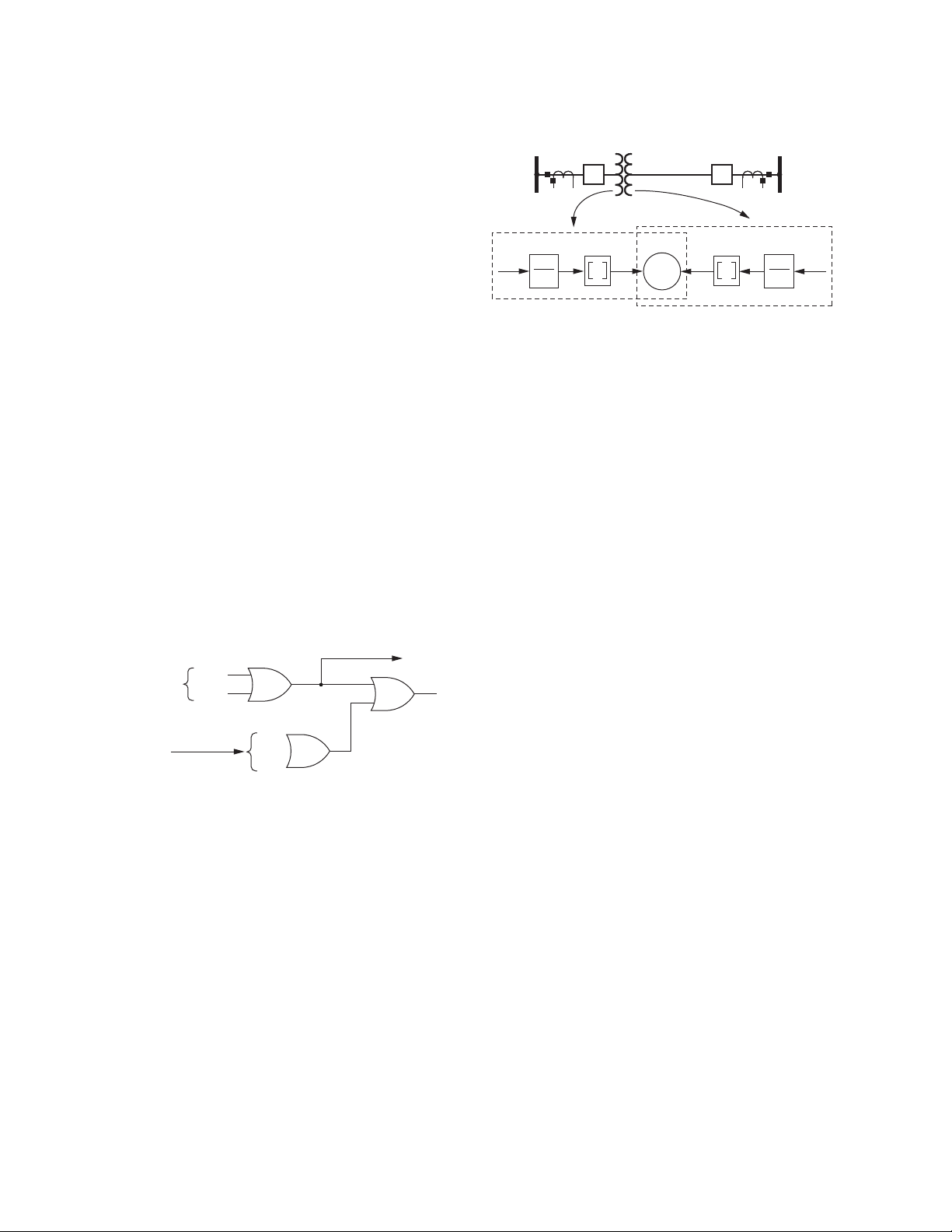
The EFD Relay Word in Figure 7 is an OR combination
of the local and remote external fault detectors. This allows
all terminals to receive an alert about an external fault
even if one of the terminals has minimal current contri-
bution to the fault. Upon assertion of the EFD Relay Word
bit, all 87L elements switch to high security mode. No
user settings are necessary for the EFD logic.
In-Line Transformers
The 87L function performs in-line power transformer
vector group, ratio, and zero-sequence compensation. The
function also provides logic for blocking during overex-
citation conditions and offers both harmonic restraint and
blocking to accommodate transformer inrush. Proper com-
pensation of the measured current occurs at the local relay
prior to remote terminal transmission of current data. Once
the local relay receives data from the remote terminals, it
can consume these data by using the same signal processing
and algorithms as in the plain line application (see Figure 8).
Time-Overcurrent Differential
Protection
The SEL-411L-2 allows protection of lines with tapped
loads without the current measurement at the tap. You can
make such partial line current differential applications
selective, and these may be acceptable if you connect
tapped and unmeasured load through a step-down power
transformer. The transformer impedance reduces the level
of line differential currents for network faults fed from
the low side of the transformer, providing better coordina-
tion margins.
This application allows you to protect lines having multi-
ple load taps without the need to invest in high-grade
communications and install the SEL-411L-2 relays at
every tap of the line.
Overall, in the partial line current differential applications of
the SEL-411L-2, we suggest following this approach:
➤The 87L elements are applied as instantaneous but
are intentionally desensitized to prevent operation
for faults in the tapped load.
➤The differential time overcurrent elements provide
sensitive, but time-coordinated protection for the
low-current line faults, some internal faults in the
tapped transformer, and remote back-up for short-
circuit protection in the tapped load network.
Use the selectable time-overcurrent elements to config-
ure the differential time-overcurrent protection while
coordinating with the phase-, negative-, or zero-sequence
short-circuit protection of the tapped load network.
Security With Respect to
Communication Events
Noise in a communications channel can corrupt data. The
SEL-411L-2 uses a 32-bit BCH code to protect data
integrity. Any data integrity protection has a non-zero
probability of defeat. To reduce the probability that a
standing noise condition could result in corrupted data
Figure 7 Combined External Fault Detector
EFDAC
EFDDC EFD
EFD1
EFD2
. . .
Local Terminal
To Outgoing Packets
Remote Terminals
(Incoming Packets)
Figure 8 Compensation for In-Line Transformers at the
Local Relay Allows the Algorithms to Remain Unchanged
87
L+T
Relay 1
CT 1 CT 2
Relay 2
iCT1 iCT2
1
TAP1
T1T21
TAP2

Schweitzer Engineering Laboratories, Inc. SEL-411L-2 Data Sheet
9
and an unwanted 87L operation, the SEL-411L-2 has
sensitive and fast-acting disturbance detectors as
Figure 9 illustrates.
Corrupted data that would activate the 87L elements or
assert the 87 direct transfer trip (87DTT) would be short
lived and constitute typically just a single packet. The
SEL-411L-2 supervises the 87L elements and 87DTT
with the disturbance detector. As Figure 10 illustrates,
the 87L element or 87DTT element is delayed slightly
without losing dependability even if the disturbance
detectors were to fail to assert.
The disturbance detectors are sensitive, but they will not
assert under load conditions for periodic current or volt-
ages, even for heavily distorted load current or voltages.
No user settings are necessary for the disturbance detec-
tion logic.
87 Channel Monitoring
To aid commissioning and to help maintain security and
dependability, the SEL-411L-2 provides a set of channel
monitoring and alarming functions. Considering that the
87L function is communications-dependent, it is benefi-
cial to monitor the status of the communications chan-
nels. The 87L function itself responds to some monitored
channel characteristics in real time to maintain proper
security and dependability.
The monitoring functions of the SEL-411L-2 include a
round-trip channel delay, step change in the round-trip
delay signifying path switching, noise burst and momen-
tary channel break detection, channel asymmetry, 40 sec-
ond and 24h lost packet counts, data integrity alarm, and
wrong relay address alarm signifying cross-connection
of communications paths. These monitoring functions
provide overall assessment of channel quality for the user
and feed into the internal 87L logic for security.
87L Communications Report
The SEL-411L-2 provides an 87L communications
report to visualize and summarize basic 87L configura-
tion, as well as real-time and historical channel monitor-
ing and alarming values. The report covers three major
areas:
➤87L configuration and overall status such as relay
identification, number of terminals in the 87L scheme,
master or slave mode, channel problems, stub bus
condition, in test, etc.
➤Detailed channel configuration, diagnostics, and
health information on a per-channel basis. Such
information includes remote relay address, data
synchronization method and status, list of any specific
channel alarms asserted, round-trip channel delay,
and channel asymmetry.
➤Long-term channel characteristics on a per-channel
basis as channel delay histogram, and worst-case
channel delay with time stamp.
87L Channel Redundancy
The SEL-411L-2 provides optional channel redundancy
in two-terminal serial applications. You can order the
SEL-411L-2 with two 87L serial communications ports,
which you can then use to connect two relays in a redun-
dant fashion, incorporating different, typically indepen-
dent communications equipment and paths. Often a
direct point-to-point fiber connection is the primary
channel, and a multiplexed channel over a SONET net-
work serves as backup. The SEL-411L-2 simultaneously
sends data on both channels, and incorporates channel
monitoring functions and logic to automatically switch
between the primary and backup channels on the receiv-
ing end to maximize dependability and security. Exces-
sive round-trip channel delay, elevated lost packet
counts, detected channel asymmetry, and user-program-
mable conditions can all serve as triggers to initiate chan-
nel switchover.
87L SEL-411L Model Interoperability
The SEL-411L-2 is compatible with other versions of
SEL-411L, which include SV, TiDL and conventional
connections. For firmware compatibility, see the
SEL-411L Instruction Manual.
Figure 9 Adaptive Disturbance Detector Algorithm
Figure 10 SEL-411L-2 Disturbance Detection
Application
kTH
1-cycle
buffer
–IIR
Filter
87DD
IN mag
∑
τ1
87DD
87LΦ
0
τ1
0
87DD
87PRAW
87DTTRECEIVED
87DTT
(To Trip Logic)
(To Trip Logic)

SEL-411L-2 Data Sheet Schweitzer Engineering Laboratories, Inc.
10
Complete Distance Protection
The SEL-411L-2 simultaneously measures as many as
five zones of phase and ground mho distance protection
plus five zones of phase and ground quadrilateral dis-
tance protection. You can apply these distance elements,
together with optional high-speed distance elements, in
communications-assisted and step-distance protection
schemes. You can use expanded SELOGIC control equa-
tions to tailor the relay further to your particular application.
The relay includes LOP detection, load encroachment,
and CCVT transient detection logic for enhanced security.
Optional series-compensated line logic can also be added
to prevent overreach of the Zone 1 distance element,
resulting from the series capacitor transient response.
Each of the distance elements has a specific reach setting.
The ground distance elements include three zero-sequence
compensation factor settings (k01, k0R, and k0F) to cal-
culate ground fault impedance accurately. Setting k01
uses positive-sequence quantities to adjust zero-sequence
transmission line impedance for accurate measurement.
Settings k0F and k0R account for forward and reverse
zero-sequence mutual coupling between parallel trans-
mission lines.
Figure 11–Figure 14 show the performance times of the
high-speed and standard distance elements for a range of
faults, locations, and source impedance ratios (SIR).
Subcycle Tripping Times Using Optional High-Speed Distance Elements
Figure 11 Mho Single-Phase-to-Ground Faults
Figure 12 Mho Phase-to-Phase Faults
Figure 13 Quadrilateral Single-Phase-to-Ground Faults
Fault Location as % of Reach Setting
0% 20% 40% 60% 80% 100%
Time in Cycles
Standard Speed Mho Ground Elements
0.25
0.50
0.75
1.25
1.50
1.0
1.75
0
SIR = 0.1
SIR = 1.0
SIR = 10.0
Fault Location as % of Reach Setting
0% 20% 40% 60% 80% 100%
Time in Cycles
High Speed Mho Ground Elements
0.25
0.50
0.75
1.25
1.50
1.0
1.75
0
SIR = 0.1
SIR = 1.0
SIR = 10.0
Fault Location as % of Reach Setting
0% 20% 40% 60% 80% 100%
Time in Cycles
Standard Speed Mho Phase Elements
0.25
0.50
0.75
1.25
1.50
1.0
1.75
0
SIR = 0.1
SIR = 1.0
SIR = 10.0
Fault Location as % of Reach Setting
0% 20% 40% 60% 80% 100%
Time in Cycles
High Speed Mho Phase Elements
0.25
0.50
0.75
1.25
1.50
1.0
1.75
0
SIR = 0.1
SIR = 1.0
SIR = 10.0
Fault Location as % of Reach Setting
0% 20% 40% 60% 80% 100%
Time in Cycles
Standard Speed Quad Ground Elements
0.25
0.50
0.75
1.25
1.50
1.0
1.75
0
SIR = 0.1
SIR = 1.0
SIR = 10.0
Fault Location as % of Reach Setting
0% 20% 40% 60% 80% 100%
Time in Cycles
High Speed Quad Ground Elements
0.25
0.50
0.75
1.25
1.50
1.0
1.75
0
SIR = 0.1
SIR = 1.0
SIR = 10.0

Schweitzer Engineering Laboratories, Inc. SEL-411L-2 Data Sheet
11
Mho Distance Elements
The SEL-411L-2 uses mho characteristics for phase and
ground distance protection. Two zones are fixed in the
forward direction, and the remaining three zones can be
set for either forward or reverse. All mho elements use
positive-sequence memory polarization that expands the
operating characteristic in proportion to the source imped-
ance (Figure 15). This provides dependable, secure oper-
ation for close-in faults.
As an optional addition to the standard distance elements,
there are three zones (either three forward, or two forward
and one reverse) of high-speed distance elements. These
high-speed elements use voltage and current phasors derived
from a fast half-cycle filter to provide subcycle tripping
times. Settings are automatically associated with the stan-
dard element zone reach, requiring no additional settings.
Quadrilateral Distance Elements
The SEL-411L-2 provides five zones of quadrilateral
phase and ground distance characteristics for improved
fault and arc resistance coverage including applications to
short lines. The top line of the quadrilateral characteristic
automatically tilts with load flow to avoid under- and
overreaching. Available settings prevent overreaching of
the quadrilateral characteristic from nonhomogeneous
fault current components. You can choose to disable the
mho and quadrilateral distance elements or use them
either separately or concurrently.
Directional Elements
The SEL-411L-2 includes a number of directional elements
for supervision of overcurrent elements and distance ele-
ments. The negative-sequence directional element uses
the same patented principle proven in the SEL-321 and
SEL-421 relays.
The following three directional elements working together
provide directional control for the ground overcurrent
elements:
➤Negative-sequence voltage-polarized directional
element
➤Zero-sequence voltage-polarized directional element
➤Zero-sequence current-polarized directional element
Our patented Best Choice Ground Directional Element
selects the best ground directional element for system
conditions and simplifies directional element settings.
(You can override this automatic setting feature for spe-
cial applications.)
Communications-Assisted
Tripping Schemes
Use MIRRORED BITS communications with SEL fiber-optic
transceivers for 3–6 ms relay-to-relay transmission time for
pilot-tripping schemes. The relay supports communica-
tions ports or conventional inputs for the communications-
assisted schemes that are independent and isolated from
the 87L communications. This allows for true redundancy
between the 87L channels and communications-assisted
scheme channels. Among the schemes supported are the
following:
➤Permissive overreaching transfer tripping (POTT)
for two- or three-terminal lines
➤Directional comparison unblocking (DCUB) for
two- or three-terminal lines
➤Directional comparison blocking (DCB)
Figure 14 Quadrilateral Phase-to-Phase Faults
Fault Location as % of Reach Setting
0% 20% 40% 60% 80% 100%
Time in Cycles
Standard Speed Quad Phase Elements
0.25
0.50
0.75
1.25
1.50
1.0
1.75
0
SIR = 0.1
SIR = 1.0
SIR = 10.0
Fault Location as % of Reach Setting
0% 20% 40% 60% 80% 100%
Time in Cycles
High Speed Quad Phase Elements
0.25
0.50
0.75
1.25
1.50
1.0
1.75
0
SIR = 0.1
SIR = 1.0
SIR = 10.0
Figure 15 Mho Characteristic
Expanded
Characteristic
Steady State
Characteristic
Relay Reach
Z
R
Z
S
X
R

SEL-411L-2 Data Sheet Schweitzer Engineering Laboratories, Inc.
12
Use the SELOGIC control equation TRCOMM to program
specific elements, combinations of elements, inputs, etc.,
to perform communications scheme tripping and other
scheme functions. The logic readily accommodates the
following conditions:
➤Current reversals
➤Breaker open
➤Weak-infeed conditions
➤Switch-onto-fault conditions
Step-distance and time-overcurrent protection provide
reliable backup operation should the communications
channel be lost.
Out-of-Step Detection
The relay provides two different algorithms for out-of-
step detection. One of the two schemes may be selected
by the user.
The zero-setting method requires no power system studies
or any settings (other than enabling). Using local voltage
measurements (see Figure 16) to closely approximate the
swing center voltage (SCV) allows the relay to use the rate-
of-change of SCV to quantify the power swing condition.
The second algorithm is a conventional out-of-step detec-
tion that provides timers and blinders that are set outside
any of the distance element reach settings. A power swing
is declared when an impedance locus travels through the
blinders slower than a preset time.
Broken Conductor Detection
The BCD element is designed to detect a conductor break
before it converts into a shunt fault. The BCD element
can help in mitigating possible fire or public hazard. The
detection logic compares the measured current against the
line charging current threshold and uses the angular dif-
ference between the phase voltage and phase current to
detect the conductor break. Additionally, the BCD func-
tion includes fault locating and phase identification to
assist the user in restoring service. The BCD element can
be applied to multiterminal overhead lines, hybrid lines
and tapped lines.
Combined Current for
Protection Flexibility
For traditional relays, when protecting a line fed from two
breakers, such as a breaker-and-a-half system or double-
breaker system, you must parallel the CTs before con-
necting these inputs to the relay. The relay accepts two
separate CT inputs (these CTs can be a different ratio)
and combines the currents mathematically. This allows
collecting separate current metering and breaker monitor
information for each breaker. Breaker failure functions
are also available on a per-breaker basis. Breaker diag-
nostic reports from the SEL-411L provide you compara-
tive breaker information that you can use for advanced,
proactive troubleshooting.
Multifunction Recloser With
Flexible Applications
The SEL-411L-2 includes both single-pole and three-
pole trip and reclose functions for either one or two
breakers (Figure 17). Synchronism check is included for
breaker control. Synchronizing and polarizing voltage
inputs are fully programmable with dead line/dead bus
closing logic, as well as zero-closing-angle logic to mini-
mize system stress upon reclosing. Program as many as
two single-pole reclose attempts, four three-pole reclose
attempts, and combined single-/three-pole reclosing
sequences. Select leader and follower breakers directly,
or use a SELOGIC control equation to determine reclos-
ing order based on system conditions. Coupled with
Figure 16 Applying VS to Approximate the Swing Center Voltage Provides an Accurate Local Quantity to Detect Power Swings
θ
I
Vcosϕ
ϕ
SCV
Swing Center
SCV ≅VS • cos(ϕ)
O’ Z1R • I
Z1S • I Z
L1
I
V
R
E
R
V
S
E
S

Schweitzer Engineering Laboratories, Inc. SEL-411L-2 Data Sheet
13
independent-pole-operating circuit breakers, this reclos-
ing system gives maximum flexibility for present system
conditions and for future requirements.
Application Examples
The SEL-411L-2 allows applications of the 87L function
in one of several configurations, for which you can pro-
vide control through use of the E87CH (Enable 87 Chan-
nel) or 87PCH (87 Primary Channel) settings. The
application examples are shown with conventional cur-
rent and voltage inputs. These signals are provided by a
remote data acquisition system in this relay.
Two-Terminal Application With a Dual
Serial Channel (E87CH = 2SD)
Set E87CH = 2SD when two communications channels
are available. Figure 18 shows an application consisting
of two SEL-411L-2 relays, each having two serial 87L
ports that are connected by using two serial channels. This
application provides for channel redundancy by using
channel switch-over logic. The 87PCH setting controls
which channel is the primary channel (i.e., the channel the
SEL-411L-2 uses for the 87L function if both channels
are available and of equal quality). The primary channel
can be direct point-to-point fiber, and the secondary
channel can be a multiplexed channel.
Three-Terminal Master Application With
Serial Channels (E87CH = 3SM)
Figure 19 shows an SEL-411L-2 set to 3SM, in which
the relay uses two serial channels to communicate with
two remote peers in a three-terminal application. If two
channels are installed, connecting each relay with both of
its remote peers, set E87CH in all relays to 3SM.
Three-Terminal Slave Application With a
Serial Channel (E87CH = 3SS)
With a similar configuration to Figure 19, you can also
use a single primary relay with two remote peers for three-
terminal applications. With no connection between two
of the relays, the single primary relay performs the differ-
ential calculation with the data provided by the two remote
peer relays. The single primary relay then issues a trip
via a direct transfer trip (87DTT) to the remote peer relays.
The SEL-411L-2 can be installed with conventional
SEL-411L relays. Figure 20 shows a mixed 87L applica-
tion of the SV, TiDL technology and conventional
SEL-411L.
Figure 17 Two-Breaker Reclosing With Synchronism Check
Figure 18 Two-Terminal Application With Hot Standby
Channel
52-1
52-2
Line
Bus 2
Bus 1
79
25
25
Relay
Dedicated Fiber
Hot Standby
Channel
Bay 1
Bay 2
Bay 1
Bay 2 Relay
Digital
Multiplexer
Digital
Multiplexer
Figure 19 Three-Terminal 3SM Configuration With All
Relays as Masters
Figure 20 Mixed 87L Application
Relay
(Optional)
(Master)
(Slave)
Relay
Relay
(Slave)
Bay 1
Bay 2
Bay 1
Bay 2
Bay 1
Bay 2
CH1
CH2
CH1
CH2 CH1
CH2
87L Channels
SV Merging Unit

SEL-411L-2 Data Sheet Schweitzer Engineering Laboratories, Inc.
14
In-Line Transformers
For lines with transformers, the preferred application is
to apply separate relays for the line current differential
zone and the transformer differential zone, as shown in
Figure 21. This allows application of fault location
(transformer vs. line faults, exact location for line faults)
and reclosing features. A direct transfer trip from the 87T
to the 87L allows fast clearing of transformer zone faults.
However, another solution is to use the SEL-411L-2 as a
current differential relay for the combined line and trans-
former zones as shown in Figure 22. This is an economic
alternative if neither reclosing nor multiterminal fault
locating are necessary.
Additional Features
Front-Panel Display
The LCD shows event, metering, setting, and relay self-
test status information. The target LEDs display relay
target information as shown in Figure 23.
The LCD is controlled by the navigation pushbuttons
(Figure 24), automatic messages the relay generates, and
user-programmed analog and digital display points. The
rotating display scrolls through alarm points, display points,
and metering screens. If none are active, the relay scrolls
through displays of the fundamental and rms metering
screens. Each display remains for a user-programmed
time (1–15 s) before the display continues scrolling. Any
message the relay generates because of an alarm condition
takes precedence over the rotating display.
Figure 23 and Figure 24 show close-up views of the front
panel of the SEL-411L-2. The front panel includes a
128 x 128 pixel, 3" x 3" LCD screen; LED target indica-
tors; and pushbuttons with indicating LEDs for local con-
trol functions. The asserted and deasserted colors for the
LEDs are programmable. Configure any of the direct-
acting pushbuttons to navigate directly to any HMI menu
item for fast viewing of events, alarm points, display
points, or the SER.
Figure 21 Preferred Application for Lines With
Transformer
Figure 22 In-Line Transformer With Combined Line and
Transformer Current Differential
87T
87L 87L
Communications
Channel
DTT
87
L+T
87
L+T
Communications Channel
Figure 23 Factory-Default Status and Trip Target LEDs
(12 Pushbutton, 24 Target LED Option)
Figure 24 Factory-Default Front-Panel Display and
Pushbuttons
03/15/11 GROUP 1
00:00:05.387
EVENT: BCG T
LOCATION: 48.47
FREQ: 60.00
SHOT: 1P=0 3P=1
BK1 OPEN
BK2 CLOSED
EVENT SUMMARY 10002

Schweitzer Engineering Laboratories, Inc. SEL-411L-2 Data Sheet
15
Bay Control
The SEL-411L-2 provides dynamic bay one-line diagrams
on the front-panel screen with disconnect and breaker
control capabilities for user-selectable bay types. You can
download the Grid Configurator interface from
selinc.com to obtain additional user-selectable bay types.
The bay control can control as many as ten disconnects
and two breakers, depending on the one-line diagram
selected. Certain one-line diagrams provide status for as
many as three breakers and five disconnect switches.
Operate disconnects and breakers with ASCII com-
mands, SELOGIC control equations, Fast Operate Mes-
sages, and from the one-line diagram. The one-line
diagram includes user-configurable apparatus labels and
as many as six user-definable analog quantities.
One-Line Bay Diagrams
The SEL-411L-2 offers a variety of preconfigured one-
line diagrams for common bus configurations. Once you
select a one-line diagram, you can customize the names for
all of the breakers, disconnect switches, and buses. Most
one-line diagrams contain analog display points. You can
set these display points to any of the available analog
quantities (including remote 87L currents) with labels,
units, and scaling. The SEL-411L-2 updates these values
along with the breakers and switch position in real time
to give instant status and complete control of a bay. The
following diagrams demonstrate some of the preconfig-
ured bay arrangements available in the SEL-411L-2.
Programmable interlocks help prevent operators from
incorrectly opening or closing switches or breakers. The
SEL-411L-2 not only prevents operators from making an
incorrect control decision, but it can notify and/or alarm
upon initiation of an incorrect operation.
Circuit Breaker Operations From the
Front Panel
Figure 25–Figure 28 are examples of some of the select-
able one-line diagrams in the SEL-411L-2. Select the
one-line diagram from the Bay settings. Additional set-
tings for defining labels and analog quantities are also
found in the Bay settings. One-line diagrams are com-
posed of the following:
➤Bay names and bay labels
➤Busbar and busbar labels
➤Breaker and breaker labels
➤Disconnect switches and disconnect switch labels
➤Analog display points
Figure 29 shows the breaker control screens available
when the ENT pushbutton is pressed with the circuit
breaker highlighted as shown in Figure 29(a).
Figure 25 Breaker-and-a-Half
Figure 26 Ring Bus With Ground Switch
Figure 27 Double Bus/Double Breaker
Figure 28 Source Transfer Bus
BAYNAME
BK2
BK1
SW1 SW2
BK3
BAYLAB2BAYLAB1
BUSNAM1
BUSNAM2
ESCNAVIG
BAYNAME
6 ANALOGS
I:99999.9 A
V:99999.9 KV
P:99999.9 MW
Q:99999.9 MV
F:99.9 HZ
BAYLAB1
SW2
SW3
BK1
BK2
SW1
BAYLAB2
ESCNAVIG
BAYNAME
6 ANALOGS
I:99999.9 A
V:99999.9 KV
P:99999.9 MW
Q:99999.9 MV
F:99.9 HZ
BUSNAM1
SW2
SW3
BK1 BK2
SW1
BUSNAM2
ESCNAVIG
BAYNAME
BUSNAM1
BK1 BK2
BUSNAM2
BAYLAB1
I:99999.9 A
V:99999.9 KV
P:99999.9 MW
I:99999.9 A
V:99999.9 KV
P:99999.9 MW
ESCNAVIG

SEL-411L-2 Data Sheet Schweitzer Engineering Laboratories, Inc.
16
Rack-Type Breakers Mosaics
The SEL-411L-2 supports the display of rack-type (also
referred to as truck-type) circuit breakers. The rack-type
breakers have three positions: racked out, test, and racked
in. When in the test or racked-in positions, the breaker
can be displayed as open or closed. When racked out, no
breaker open/close display are available. The rack-type
breakers are a display-only functionality and do not impact
any circuit breaker control capabilities.
Status and Trip Target LEDs
The SEL-411L-2 includes programmable status and trip
target LEDs, as well as programmable direct-action con-
trol pushbuttons on the front panel. Figure 23 shows these
targets.
The SEL-411L-2 features a versatile front panel that you
can customize to fit your needs. Use SELOGIC control
equations and slide-in configurable front-panel labels to
change the function and identification of target LEDs
and operator control pushbuttons and LEDs. The blank
slide-in label set is included with the SEL-411L-2. You
can use templates supplied with the relay or hand label
supplied blank labels and print label sets from a printer.
Alarm Points
You can display messages on the SEL-411L-2 front-
panel LCD that indicate alarm conditions in the power
system. The relay uses alarm points to place these mes-
sages on the LCD.
Figure 30 shows a sample alarm points screen. The relay
can display as many as 66 alarm points. The relay auto-
matically displays new alarm points while in manual-
scrolling mode and in autoscrolling mode. You can con-
figure the alarm points message and trigger it either
immediately by using inputs, communications, or condi-
tionally by using powerful SELOGIC control equations.
The asterisk next to the alarm point indicates an active
alarm. Use the front-panel navigation pushbuttons to
clear inactive alarms.
Figure 29 Screens for Circuit Breaker Selection
Bus Labels
BAYNAME
BAYNAME
OPEN BREAKER
CLOSE BREAKER
OPEN
Bkrnam
PRESS TO ACTIVATE
Bay not in
LOCAL Control!
Cannot issue
controls.
Press ENT with breaker highlighted
Breaker
Highlighted
(a) Bay Screen
(c) LOCAL bit NOT asserted
(b) Breaker Control Screen
After three seconds,
re-display the previous screen
BUS 2
Dis 4
Bkr 1
Dis 3
Dis 1 Dis 2
BUS 1
BUS T
Bay Name
Disconnect
Switch Label
Disconnect
Switch Label
Disconnect
Switch Label
Analog
Quantities
Display
Breaker
Label
6 ANALOGS
I:99999.9 A
V:99999.9 KV
P:99999.9 MW
Q:99999.9 MV
F:60.000 HZ
ESCNAVIG
ESCNAVIG

Schweitzer Engineering Laboratories, Inc. SEL-411L-2 Data Sheet
17
Advanced Display Points
Create custom screens showing metering values, special
text messages, or a mix of analog and status information.
Figure 31 shows an example of how you can use display
points to show circuit breaker information and current
metering. You can create as many as 96 display points.
All display points occupy only one line on the display at
all times. The height of the line is programmable as either
single or double, as shown in Figure 31. These screens
become part of the autoscrolling display when the front
panel times out.
Communications Features
See Specifications on page 29 for specific supported protocols.
The relay offers the following communications features:
➤Four independent EIA-232 serial ports.
➤Access to event history, relay status, and meter
information from the communications ports.
➤Password-controlled settings management and
automation features.
➤SCADA interface capability, including FTP,
IEC 61850, DNP3 LAN/WAN (via Ethernet), and
DNP3 (via serial port). The relay does not require
special communications software. You only need
ASCII terminals, printing terminals, or a computer
supplied with terminal emulation and a serial
communications port.
➤Synchrophasor data at 60 message-per-second data
format.
Ethernet Card
The Ethernet card has five small form-factor pluggable
(SFP) ports.aPORT 5A and PORT 5B are reserved for the
process bus network. PORT 5C and PORT 5D are reserved
for the station bus network. The process and station bus
networks support PRP and fast failover redundancy
modes. PORT 5E operates on an isolated network with a
unique IP address making it ideal for engineering and
data access. All ports support 100 Mbps speeds. PORT 5A
and PORT 5B also support 1 Gbps speeds to satisfy poten-
tially large traffic requirements on the process bus. The
process bus, station bus, and engineering access net-
Figure 30 Sample Alarm Points Screen
*Unauthorized Access
*LOP Asserted
*SF6 Low Bk1
ALARM POINTS
Press to acknldge
Figure 31 Sample Display Points Screen
Circuit Breaker 1
--Closed--
DISPLAY POINTS
Circuit BK1 SF6 Gas
--Alarm--
Circuit Breaker 2
A PH= 119.6 A pri
SF6 ALARM
Figure 32 System Functional Overview
87L Serial Communication:
Channel 1
Channel 2 (optional)
1550 nm
1300 nm
1300 nm C37.94
850 nm C37.94
EIA-422
G.703 SEL-411L Communication
Automation or Synchrophasors
Over Ethernet:
Five Ethernet Ports
(PORT 5A, PORT 5B, PORT 5C,
PORT 5D, and PORT 5E)
100BASE-FX
1000BASE-X
To Remote
SEL-411L
To SEL ICON
C37.118
To Remote SEL Relay
Using MIRRORED BITS
Spare
Front Port Local
Operator or
Engineering Access
IEC 61850 or
DNP LAN/WAN
Communications
Processor
Serial Communication:
Three Rear EIA-232 Ports
One Front EIA-232 Port
aSFP transceivers are not included with the card and must be ordered
separately. See selinc.com/products/sfp for a list of compatible SFP
transceivers.

SEL-411L-2 Data Sheet Schweitzer Engineering Laboratories, Inc.
18
works use separate MAC addresses and are logically
delineated, including in the Configured IED Description
(CID) file.b
Use popular Telnet applications for easy terminal com-
munications with SEL relays and other devices. Transfer
data at high speeds for fast file uploads. The Ethernet
card communicates using FTP applications for easy and
fast file transfers.
Communicate with SCADA by DNP3 and other substa-
tion IEDs by using IEC 61850 Manufacturing Message
Specification (MMS) and GOOSE messaging.
Choose Ethernet connection media options for primary
and standby connections:
➤10/100BASE-T twisted pair networkc
➤100BASE FX fiber-optic network
➤1000BASE-X fiber-optic networkd
Telnet and FTP
Use Telnet to access relay settings, metering, and event
reports remotely by using the ASCII interface. Use FTP
to transfer settings files to and from the relay via the
high-speed Ethernet port.
DNP3 LAN/WAN
DNP3 LAN/WAN provides the relay with DNP3 Level 2
Outstation functionality over Ethernet. Configure DNP3
data maps for use with specific DNP3 masters.
PTP
The Ethernet card provides the ability for the relay to accept
IEEE 1588 PTPv2 for data time synchronization. PTP
support includes the Default, Power System, and Power
Utility Automation Profiles. When connected directly to
a grandmaster clock providing PTP at 1-second synchro-
nization intervals, the relay can be synchronized to an
accuracy of ±100 ns in the PTP time scale.
SNTP Time Synchronization
Use SNTP to synchronize relays to as little as ±1 ms with
no time source delay. Use SNTP as a primary time source,
or as a backup to a higher accuracy time input to the relay.
PRP
Use PRP to provide seamless recovery from any single
Ethernet network failure, in accordance with IEC 62439-3.
The Ethernet network and all traffic are fully duplicated
with both copies operating in parallel.
HTTP Web Server
The relay can serve read-only webpages displaying cer-
tain settings, metering, and status reports. The web server
also allows quick and secure firmware upgrades over
Ethernet. As many as four users can access the embedded
HTTP server simultaneously.
IEC 61850 Ethernet Communications
IEC 61850 Ethernet-based communication protocols
provide interoperability between intelligent devices within
the substation. Standardized logical nodes allow inter-
connection of intelligent devices from different manufac-
turers for monitoring and control of the substation.
Eliminate system RTUs by streaming monitor and con-
trol information from the intelligent devices directly to
remote SCADA client devices.
bThis paragraph describes the five-port Ethernet card ordering option.
It does not apply to the four-port Ethernet card ordering option.
cFour-port Ethernet card ordering option only.
dGigabit speeds are only available on PORT 5A and PORT 5B of the five-
port Ethernet card ordering option.
Figure 33 Example PTP Network
GPS

Schweitzer Engineering Laboratories, Inc. SEL-411L-2 Data Sheet
19
You can order the relay with IEC 61850 protocol for relay
monitor and control functions, including:
➤As many as 128 incoming GOOSE messages. You
can use the incoming GOOSE messages to control
as many as 256 control bits in the relay with <3 ms
latency from device to device depending on network
design. These messages provide binary control
inputs to the relay for high-speed control functions
and monitoring.
➤As many as eight outgoing GOOSE messages.
Configure outgoing GOOSE messages for Boolean
or analog data such as high-speed control and
monitoring of external breakers, switches, and other
devices. Boolean data are provided with <3 ms latency
from device to device depending on network design.
➤IEC 61850 Data Server. The relay equipped with
embedded IEC 61850 Ethernet protocol provides
data according to predefined logical node objects.
Each relay supports as many as seven unbuffered
MMS report client associations. Relevant Relay
Word bits are available within the logical node
data, so status of relay elements, inputs, outputs, or
SELOGIC control equations can be monitored.
➤As many as 256 virtual bits. Configure the virtual
bits within GOOSE messaging to represent a variety
of Boolean values available within the relay. These
bits that the relay receives are available for use in
SELOGIC control equations.
➤As many as 64 remote analog outputs. Assign the
remote analog outputs to virtually any analog quantity
available in the relay. You can also use SELOGIC
math variables to develop custom analog quantities
for assignment as remote analog outputs. Remote
analog outputs that use GOOSE messages provide
peer-to-peer transmission of analog data. Each relay
can receive as many as 256 remote analog inputs
and use those inputs as analog quantities within
SELOGIC control equations.
➤IEC 61850 standard operating modes. The relay
supports Test, Blocked, On, and Off. The relay also
supports Simulation mode for added flexibility.
MMS File Services
This service of IEC 61850 MMS provides support for file
transfers completely within an MMS session. All relay
files that can be transferred via FTP can also be transferred
via MMS file services.
MMS Authentication
When enabled via a setting in the Configured IED
Description (CID) file, the relay requires authentication
from any client requesting to initiate an MMS session.
Architect Software
Use ACSELERATOR Architect SEL-5032 Software to
manage the IEC 61850 configuration for devices on the
network. This Windows-based software provides easy-
to-use displays for identifying and binding IEC 61850
network data among logical nodes that use IEC 61850-
compliant CID files. Architect uses CID files to describe
the data available in each relay.
Serial Communications
MIRRORED BITS Communications
The SEL patented MIRRORED BITS technology provides
bidirectional relay-to-relay digital communication.
Figure 34 shows two relays with SEL-2815 Fiber-Optic
Transceivers that use MIRRORED BITS communications.
MIRRORED BITS communications can operate simultane-
ously on any two serial ports. This bidirectional digital
communication creates additional outputs (transmitted
MIRRORED BITS) and additional inputs (received
MIRRORED BITS) for each serial port operating in the
MIRRORED BITS communications mode.
Communicated information can include digital, analog,
and virtual terminal data. Virtual terminal allows opera-
tor access to remote relays through the local relay. You
can use this MIRRORED BITS protocol to transfer infor-
mation between stations to enhance coordination and
achieve faster tripping.

SEL-411L-2 Data Sheet Schweitzer Engineering Laboratories, Inc.
20
Open Communications Protocols
The relay does not require special communications software. ASCII terminals, printing terminals, or a computer sup-
plied with terminal emulation and a serial communications port are all that is required. Table 1 lists a brief description of
the terminal protocols.
Figure 34 Integral Communication Provides Secure Protection, Monitoring, and Control as Well as Terminal Access to
Both Relays Through One Connection
Fiber-Optic Cable
SEL-2815 SEL-2815
Bus 1 Bus 2
1Transmission Line 2
Digital, Analog, and Virtual Terminal Data
Other
Relays
Other
Relays
TX
RX
SEL-400 Series Relay
TX
RX
SEL-400 Series Relay
Table 1 Open Communications Protocol
Type Description
ASCII Plain-language commands for human and simple machine communications. Use for metering, setting, self-test
status, event reporting, and other functions.
Compressed ASCII Comma-delimited ASCII data reports. Allows external devices to obtain bay data in an appropriate format for
direct import into spreadsheets and database programs. Data are checksum protected.
Extended Fast Meter, Fast
Operate, and Fast SER
Binary protocol for machine-to-machine communications. Quickly updates communications processors, RTUs,
and other substation devices with metering information, bay element, I/O status, time-tags, open and close
commands, and summary event reports. Data are checksum protected. Binary and ASCII protocols operate
simultaneously over the same communications lines so that control operator metering information is not lost
while a technician is transferring an event report.
Ymodem Support for reading event, settings, and oscillography files.
Optional DNP3 Level 2
Outstation
DNP with point remapping. Includes access to metering data, protection elements, contact I/O, targets, SER,
relay summary event reports, and settings groups.
IEEE C37.118 Phasor measurement protocol.
MIRRORED BITS SEL protocol for exchanging digital and analog information among SEL relays and for use as low-speed termi-
nal connection.
IEC 61850 Ethernet-based international standard for interoperability between intelligent devices in a substation.
PRP PRP provides redundant Ethernet network capabilities for seamless operation in the event of loss to one network.
SNTP Ethernet-based SNTP for time synchronization among relays.
FTP and Telnet Use Telnet to establish a terminal-to-relay connection over Ethernet. Use FTP to move files in and out of the
relay over Ethernet.
Table of contents
Other Sel Control System manuals
Popular Control System manuals by other brands

Faulhaber
Faulhaber MC 3603 S Technical manual

micro-trak
micro-trak ProPlant Reference manual

resideo
resideo SmartValve SV9410 installation instructions

Elsner
Elsner 70191 Installation and operation

Snap-On
Snap-On LEVEL5ATC Installation and operation manual

Canalta
Canalta Combustex BMS-2000 Operation manual