OSF WATERFRIEND exclusiv MRD-1 User manual

Installation and Operating Instructions
Water treatment for pH and active oxygen
optional with web server and Internet connection
Technical Data
WATERFRIENDoxygen
Nominal voltage
1/N/PE 230V/50Hz
Metering pump pH
Peristaltic pump
Metering pump oxygen
Peristaltic pump
Flow rate pH
0 to 10 L / h
Flow rate oxygen
0 to 10 L / h
Protection class
IP 20
Housing size
500 x 390 x 130
Humidity
0 to 95%, non condensing
Surrounding temperature
0 to 40 °C
Measuring water pressure
max. 2 bar
MRD-1
Made by

Installation and operating manual for WATERFRIEND oxygen MRD-1 page 2 (42)
Table of Contents
Table of Contents .....................................................................................................................................................2
General.......................................................................................................................................................................5
Safety information ....................................................................................................................................................5
Installation and operating manual .......................................................................................................................5
Canister ...............................................................................................................................................................5
Personnel qualification ........................................................................................................................................5
Installation.................................................................................................................................................................5
Installation ...........................................................................................................................................................6
Installation in the water circuit .............................................................................................................................6
General information on installation in the water circuit........................................................................................6
Electrical power supply............................................................................................................................................7
Low-voltage cables..............................................................................................................................................7
Wiring diagram ....................................................................................................................................................7
Alarm ...................................................................................................................................................................7
External pumps....................................................................................................................................................7
Enabling...............................................................................................................................................................8
RS-485 ................................................................................................................................................................8
Connecting to EUROMATIK.net ..............................................................................................................................8
External Touch-Panel..........................................................................................................................................8
Connecting to the computer network (optional) ...................................................................................................8
Operation...................................................................................................................................................................9
Displays...............................................................................................................................................................9
Temperature........................................................................................................................................................9
Measurement water flow quantity........................................................................................................................9
Regulation status...............................................................................................................................................10
Child lock...........................................................................................................................................................10
Professional level ..............................................................................................................................................11
Bleed metering hose..........................................................................................................................................11
pH regulation...........................................................................................................................................................11
Switching off pH regulation................................................................................................................................11
Setting the pH target value................................................................................................................................12
Setting the alarm limit values ............................................................................................................................12
Setting the lower pH alarm................................................................................................................................12
Setting the upper pH alarm ...............................................................................................................................13
Setting the pH proportional range .....................................................................................................................13
Meaning of the proportional range ....................................................................................................................14
Setting the maximum pH metering time............................................................................................................15
pH metering pump flow rate ..............................................................................................................................15
pH Power-on delay............................................................................................................................................16
H2O2dosation..........................................................................................................................................................17
Interesting facts about the active oxygen dosage.............................................................................................17
Main dosage......................................................................................................................................................17
Top-up dosage ..................................................................................................................................................17
Switch off active oxygen control........................................................................................................................17
Set the parameters for active oxygen...............................................................................................................17
Set the dosing volume.......................................................................................................................................17
Set the time of the main dosage........................................................................................................................18

Installation and operating manual for WATERFRIEND oxygen MRD-1 page 3 (42)
Set the dosing plan............................................................................................................................................18
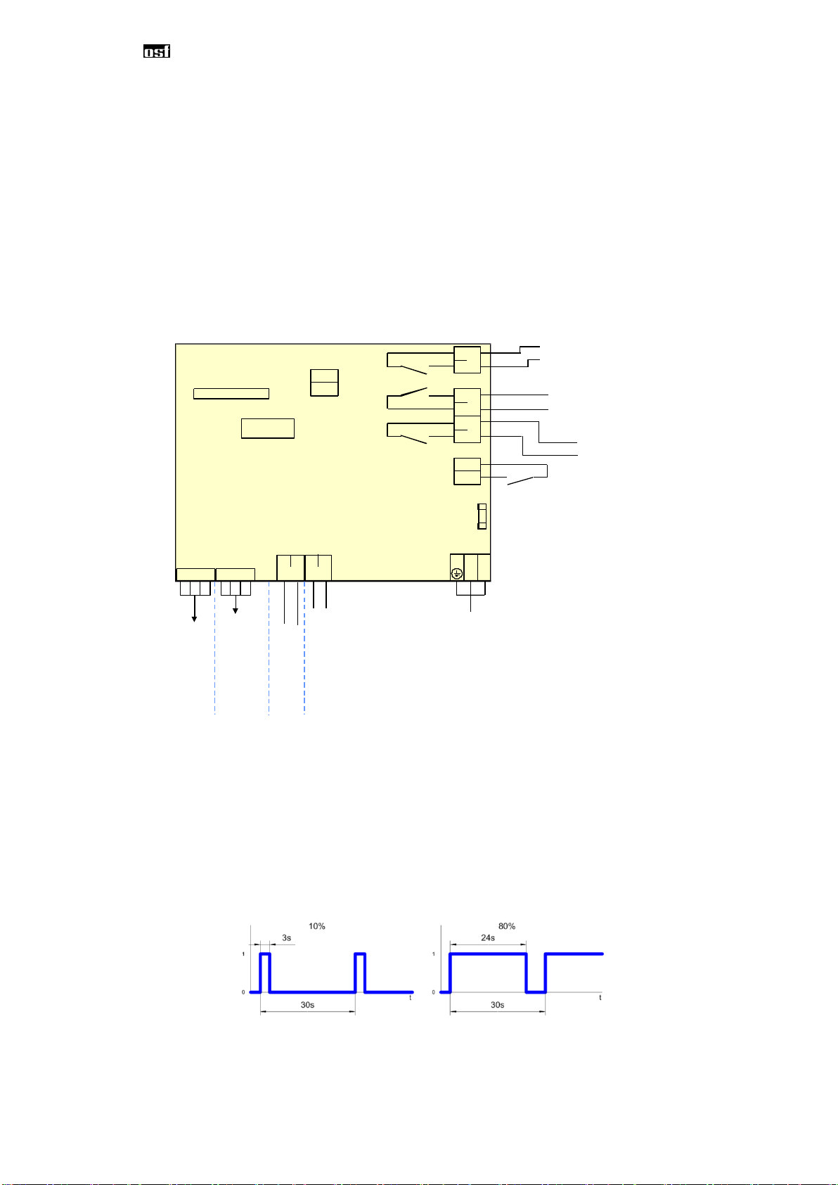
Set the delivery rate of the pump ......................................................................................................................19
Set the power-on delay of the controller............................................................................................................19
Set the temperature compensation...................................................................................................................20
Calibration...............................................................................................................................................................20
Buffer solution....................................................................................................................................................20
Electrodes..........................................................................................................................................................20
Calibrating the pH electrode..............................................................................................................................21
Calibrating the upper value (pH 7) ....................................................................................................................21
Setting the lower value (pH 4)...........................................................................................................................21
pH calibration errors ..........................................................................................................................................22
Service settings ......................................................................................................................................................22
Time and date....................................................................................................................................................22
Selecting the language......................................................................................................................................22
Operating hours after the last calibration ..........................................................................................................23
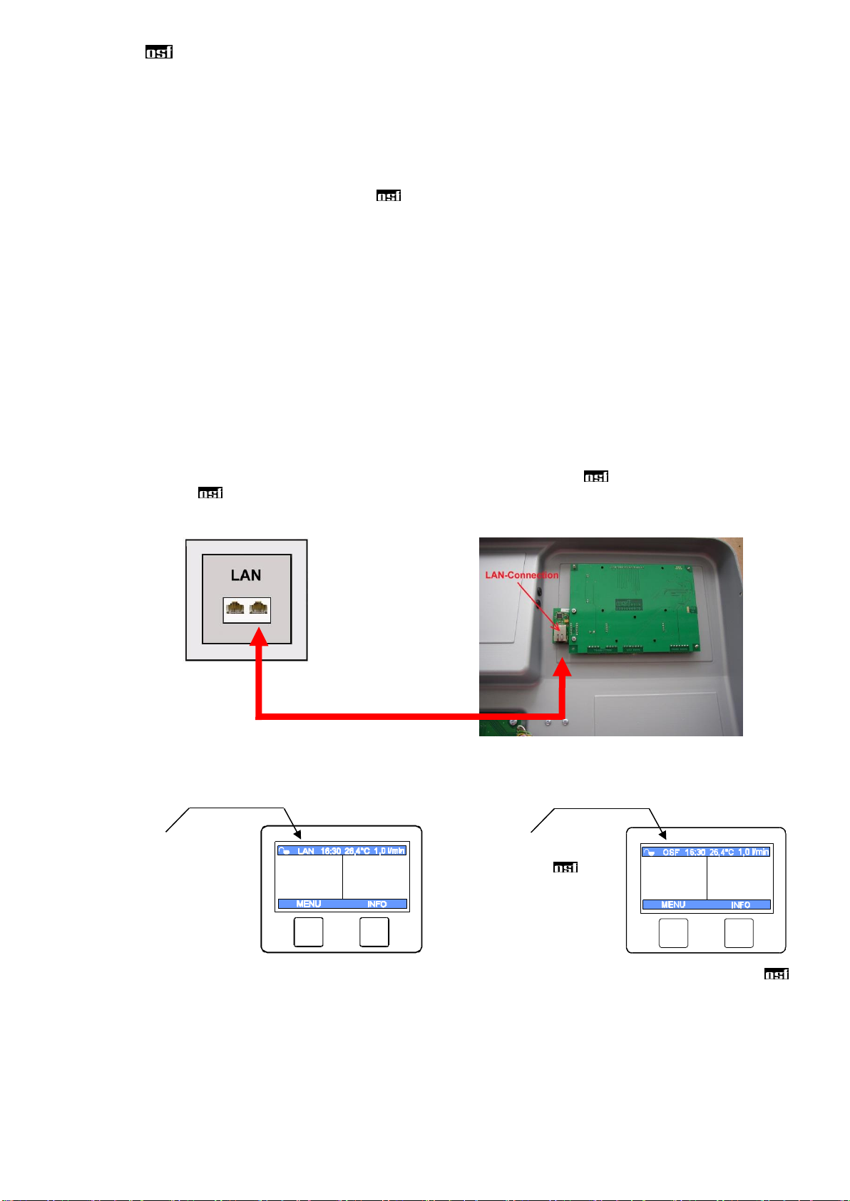
LAN settings ......................................................................................................................................................24
Access control (PIN numbers)...........................................................................................................................24
Reset all settings to factory settings..................................................................................................................24
Adjustment of temperature display....................................................................................................................25
Acoustic error message.....................................................................................................................................25
Increase pH <=> decrease pH ..........................................................................................................................26
Alarm / error message............................................................................................................................................26
Acknowledging an error message.....................................................................................................................26
Measuring chamber colors....................................................................................................................................26
Meaning of the individual colors........................................................................................................................27
Using the osf communication server ...................................................................................................................27
Communication server for pool owners...........................................................................................................28
Registering a new device with the server..........................................................................................................28
Communication server for pool installers........................................................................................................30
Registering a new control unit with the server ..................................................................................................30
Communication server with technical view .....................................................................................................32
Registering a new device with the server..........................................................................................................32
Read device ID on the display of the dosing control.........................................................................................34
Changing the PIN (password)............................................................................................................................35
Assigning a new PIN .........................................................................................................................................35
Naming the unit...................................................................................................................................................35
Entering an e-mail address................................................................................................................................35
Entering an e-mail address ...............................................................................................................................35
Assigning a name..............................................................................................................................................35
Update......................................................................................................................................................................36
Checking for updates .........................................................................................................................................36
Explanations ...........................................................................................................................................................37
Storage, Transport.............................................................................................................................................37
Maintenance............................................................................................................................................................37
6-monthly service ...................................................................................................................................................37
Sealtightness.....................................................................................................................................................37
Dirt filter .............................................................................................................................................................37
Injection valves..................................................................................................................................................37

Installation and operating manual for WATERFRIEND oxygen MRD-1 page 4 (42)
pH electrode ......................................................................................................................................................37
Metering pumps.................................................................................................................................................37
Annual service ........................................................................................................................................................37
Replacing the pH electrode...............................................................................................................................37
Replacing the metering hose.............................................................................................................................37
Decommissioning...................................................................................................................................................38
Electrode ...........................................................................................................................................................38
Flow fitting .........................................................................................................................................................38
Metering pumps.................................................................................................................................................38
Wear parts ...............................................................................................................................................................38
Interfacing with building automation systems ....................................................................................................39
Shipment of the dosing system ...........................................................................................................................41

Installation and operating manual for WATERFRIEND oxygen MRD-1 page 5 (42)
General
Safety information
Installation and operating manual
This operating manual contains important information which must be observed during installation, operation and
maintenance of the metering unit. For this reason, it is imperative that this operating manual is read by the fitter
and the responsible specialist personnel or equipment owner before installation and initial start-up. It must be
continuously available at the device installation location.
Caution
The metering liquids used are corrosive or highly flammable. The two pressure hose ends at the hose pumps
must never be hanging freely, otherwise corrosive or highly flammable liquids can be discharged.
Canister
The canisters containing the metering liquids must be placed in interception troughs. They may never be
placed directly underneath the controller. Gas-emitting chemicals can cause damage to the sensitive controller.
Personnel qualification
The personnel who will be operating, maintaining, inspecting and installing the device must have appropriate
qualifications for this work. The plant operator must precisely define the areas of responsibility, responsibilities
and monitoring of the personnel. If the personal does not have the required knowledge, they must be trained and
instructed. This can be carried out by the manufacturer or supplier on behalf of the owner if required. Furthermore,
the owner must ensure that the contents of this operating manual have been understood by his personnel in all
respects.
Installation
You have purchased a high-quality measuring, regulating and metering device with the WATERFRIEND. The
device is a precise and sensitive system which needs to be handled carefully at all times. Please handle the
protective cover carefully as well. It may not be allowed to fall down or come into contact with chemicals. The
protective cover should be cleaned using a soft cloth and a little water if necessary.
pH metering
pump
Active oxygen
metering pump
Operating
panel
Dirt filter
Overview table for
entering calibrations
carried out
Here, the buffer
solutions are set
aside and stored
Measuring
chamber
pH sensor
Drain valve
Measurement
water feed
Measurement water
return

Installation and operating manual for WATERFRIEND oxygen MRD-1 page 6 (42)
All regulations and provisions applicable to the place of installation must be observed during installation. The
swimming pool must be constructed such that a possible technical malfunction, power failure or a defective
metering system may not cause any consequential loss.
Installation
The bottom housing section is fixed vertically and permanently to a solid wall with suitable load-bearing capacity.
Please ensure that the measuring cells are vertical after this has been carried out. The installation location must
be protected against dust and water in order to guarantee correct and proper functioning of the device. The
surrounding temperature must be between -0° C und + 40° C and should be kept as constant as possible.
Humidity at the installation site may not exceed 95%, and no condensation may take place. Please avoid direct
heat or sun irradiation onto the device.
Installation in the water circuit
Please observe all valid safety regulations when carrying out installation work, and ensure that this is carried out
carefully. Disconnect the measuring, regulation and metering device and all other electrical consumers such as
filter pumps and heaters from the power supply.
General information on installation in the water circuit
Before carrying out initial start-up, ensure that the injection valves open and close reliably.
All hoses must be routed free of kinks.
Avoid routing hoses over sharp edges.
Connect all hoses carefully and check to ensure that they are tightly fitted to their connections.
Avoid unnecessarily long hose lengths.
Hoses may not be routed directly over pipes carrying heat or over other devices.
active oxygen
(H2O2)
pH
filter
metering H2O2
metering pH
measuring water
measurement
water return
filter pump
WATERFRIEND MRD-1

Installation and operating manual for WATERFRIEND oxygen MRD-1 page 7 (42)
Electrical power supply
The controller must be mounted protected against moisture in accordance with its protection class. The device
must be powered via a multi-pole main switch with a contact opening width of at least 3mm and a residual current
circuit breaker with IFN30mA. The device must be isolated before opening the housing. Electrical power
supply connections, in addition to alignment and service work, may only be carried out by approved
electricians. The attached circuit diagrams and all applicable safety regulations must be observed.
Low-voltage cables
Low-voltage cables may not be routed together with three-phase or alternating current cables in one cable duct.
Routing of low-voltage cables in the vicinity of three-phase or alternating current cables should generally be
avoided.
Wiring diagram
Steckverbinder
connector
Steckverbinder
connector
Dosierpumpe pH
dosing pump pH
Dosierpumpe
dosing pump
hydrogen peroxide
Wasserstoffperoxid
Niveau Sensor pH
level sensor pH
Niveau Sensor
level sensor
Wasserstoffperoxid
hydrogen peroxide (H2O2)
Lvl 1 Lvl 2
Netz mains
1 / N / PE 230V 50Hz
N L1
Sicherung
fuse
T2A
Alarm
Freigabe (Filtersteuerung)
enable (pool control)
PWM1 PWM2
Alarm
Externe Pumpe
external pump
Wasserstoffperoxid
hydrogen peroxide (H2O2)
Externe Pumpe pH
external pump pH
Data+
Data-
RS 485
Service-Terminal
Control Board
Alarm
An external acoustic or optical alarm can be connected to these terminals. These terminals can also be used for
connection to group error messaging systems. The terminals can be loaded with maximum 230V 1A.
External pumps
These connecting terminals are control contacts for external metering pumps. The terminals can be loaded with
maximum 230V 1A.
These outputs deliver clock signals with pulse duty factors that are proportional to the current dosing rate of the
built-in dosing pumps and thus enable the stepless control of external pumps.
For safety reasons, the two outputs are interlocked, i.e. when the pH metering pump is working, the oxygene
metering pump is always switched off.

Installation and operating manual for WATERFRIEND oxygen MRD-1 page 8 (42)
Enabling
These connecting terminals are used for interlocking with a filter control unit. Opening the floating contact within
the filter control unit causes interruption of the metering process.
RS-485
These terminals are used for connection to the Euromatik.net filter control unit. A screened, twisted, 2-core
cable (twisted pair) with a cross-section of at least 0.22 mm2 is required for the connection. (e.g. Li2YCY(TP) 2 x
0.22 mm²). Screening improves the electromagnetic compatibility (EMC). The cable length of the complete bus-
system may not exceed 1200 m. The polarity (DATA+ and DATA) must be observed.
Connecting to EUROMATIK.net
External Touch-Panel
The RS-485 connection terminals are used for data transmission to the EUROMATIK.net. Thus it can be
accessed from the external touch panel of EUROMATIK.net to the water treatment WATERFRIEND MRD-1.
Please note the instruction manual of the EUROMATIK.net.
Connecting to the computer network (optional)
Connection to the Internet is only possible for dosing controls with integrated web server (option) and is
carried out by the communication server. The WATERFRIEND MRD-1 is connected using a standard
Ethernet patch cable into the network wall outlet, the powerline adapter, the wireless LAN access point or other
suitable facilities.
After the WATERFRIEND was connected to an active network outlet, the power supply can be turned on. The
web server in WATERFRIEND now searches autonomously for the communication server and logs on to the
database.
7,20 2,5
721 2,62
D -2% Auto
HO
22
7,20 2,5
721 2,62
D -2% Auto
HO
22
If the "OSF" icon in the monitor is visible (see chart), the WATERFRIEND has logged on to the
communication server.
LAN
Connection established
OSF
Connected to
communications server
Network line / patch cable
Network
outlet

Installation and operating manual for WATERFRIEND oxygen MRD-1 page 9 (42)
Operation
Displays
7,20 1,3
721 1,4
D -2% Auto
HO
22 l
Temperature
The displayed temperature is the measurement water temperature within the flow fittings. This can deviate from
the actual water temperature in the swimming pool depending on the pipeline routing and surrounding
temperatures.
Measurement water flow quantity
Quantity of water flowing through the measuring chamber.
Child lock OFF Time Temperature Measurement water flow quantity
Current pH value
Setpoint pH
Status of the pH
controller
Actual weekly H2O2dosage
in liters
Setpoint of the weekly H2O2
dosage in liters
Status of the oxygen
controller
Current key
function
Current key
function
Confirm selected setting,
save set value
Back.
Cancel without
saving
Back to
basic display

Installation and operating manual for WATERFRIEND oxygen MRD-1 page 10 (42)
Regulation status
In the "Regulation status" fields, additional information about the respective operating status of the individual
controllers is displayed:
Display
Meaning
off
The controller is out of order
D ± xx %
Display of the current dosing rate and the dosing direction
too high
The measured value has exceeded the specified upper alarm limit value.
too low
The measured value has exceeded the specified lower alarm limit value.
flow
The control was temporarily interrupted because the sample water flow rate is
outside the permissible limits and therefore no reliable measurement is
possible.
ext. lock
The regulation was blocked by the enable signal of the filter control.
delay
The control is not yet active because the switch-on delay for stabilizing the
measured values has not yet ended
tank
The chemicals canister is empty.
pH too high
The oxygen dosing is temporarily blocked because the pH value is too high
for reliable chlorine control.
pH too low
The oxygen dosing is temporarily blocked because the pH value is too low for
reliable chlorine control.
dos. time
Dosing is blocked because the specified maximum dosing time has been
exceeded. After eliminating the cause of the error, this error message
must be acknowledged by pressing the start button on the info page.
meas. err
Dosing is blocked because the sensor is not delivering a valid measured
value.
pH problem
The oxygen dosing is blocked because the pH sensor is not delivering a valid
measured value.
transmitt.
Dosing is blocked because the measured value transmitter is not working.
error
Dosing is blocked because the control electronics are not working.
Child lock
This symbol shows the child lock status
OFF ON
The child lock is switched off as supplied.
To switch off child lock, press the
HOME
key for 5 seconds
To switch child lock on, press the
HOME
key for 5 seconds
All keys are blocked if the child lock is switched on! Only the
ESC
key is active and enables querying of the device
type.

Installation and operating manual for WATERFRIEND oxygen MRD-1 page 11 (42)
Professional level
The WATERFRIEND offers protection against unauthorised
changes to important operating parameters.
This safety function is activated as supplied. All the
parameters marked with X in the display are blocked.
Safety function OFF Safety function ON (no symbol)
To switch the safety function off, press the , and keys simultaneously.
The safety function switches itself on again automatically one hour after the last time one of these keys was
actuated.
Bleed metering hose
The WATERFRIEND offers the facility for switching the
metering pump on manually so that the meeting hoses can be
bled.
Procedure: Press the "MENU" key
Move the cursor (blue backed text) to the line "hand dosage" by pressing the keys or .
Press the
OK
key.
Each metering pump can be switched on and off individually
by pressing the appropriate keys. While doing so, please
observe the corresponding status display. The maximum
runtime is limited to 60 seconds. Once this time has elapsed,
the pumps will be switched off automatically. The remaining
runtime is shown graphically in the display.
Runtime
pH regulation
Switching off pH regulation
In the menu there is a setting to turn on and off the automatic
pH control.
Procedure: Press the "MENU" key
Move the cursor (blue backed text) to the line "set pH" by pressing the keys or .
Press the
OK
key.
Move the cursor (blue backed text) to the line "operating mode" by pressing the keys or .
Press the
OK
key.
X start delay 10
X comm. adress 1
X factory settings
X temperature correct.
7,20 1,5
721 H O l
22
1,4
Stop Stop
pH
7,20 1,3
721 HO l
22
1,4
D -2% Auto
pH
7,20
1,3
721
H2O21,4 l
D -2%
Auto
pH

Installation and operating manual for WATERFRIEND oxygen MRD-1 page 12 (42)
By pressing the arrow keys and the cursor can be
moved and the desired operating mode can be selected.
Operating mode:
OFF or AUTO
Press the
OK
key to save the settings.
Setting the pH target value
There is a setting facility for the required pH value in the
menu.
Procedure: Press the "MENU" key
Move the cursor (blue backed text) to the line "set pH" by pressing the keys or .
Press the
OK
key.
Move the cursor (blue backed text) to the line "setpoint" by pressing the keys or .
Press the
OK
key.
You can move the cursor by pressing the arrow keys and
and also use the and arrow keys to set the target value.
The maximum and minimum possible values are shown right
and left in the display.
Setpoint
Press the
OK
key to save the settings.
Setting the alarm limit values
These settings may only be adjusted by a specialist.
Setting the lower pH alarm
There is a setting facility for the required alarm limit value in
the menu.
Procedure: Press the "MENU" key
Move the cursor (blue backed text) to the line "set pH" by pressing the keys or .
Press the
OK
key.
Move the cursor (blue backed text) to the line "lower alarm" by pressing the keys or .
Press the
OK
key.
7,20 1,3
721 H O l
22
1,4
D -2% Auto
pH
MIN MAX
6,8 7,8
7,20
7,20
7,20 1,3
721 H O l
22
1,4
D -2% Auto
pH
Operation mode OFF
AUTO
Factory setting: AUTO

Installation and operating manual for WATERFRIEND oxygen MRD-1 page 13 (42)
You can move the cursor by pressing the arrow keys and
and also use the and arrow keys to set the target value.
The maximum and minimum possible values are shown right
and left in the display.
Target value
Press the
OK
key to save the settings.
Setting the upper pH alarm
There is a setting facility for the required alarm limit value in
the menu.
Procedure: Press the "MENU" key
Move the cursor (blue backed text) to the line "set pH" by pressing the keys or .
Press the
OK
key.
Move the cursor (blue backed text) to the line "upper alarm" by pressing the keys or .
Press the
OK
key.
You can move the cursor by pressing the arrow keys and
and also use the and arrow keys to set the target value.
The maximum and minimum possible values are shown right
and left in the display.
Target value
Press the
OK
key to save the settings.
Setting the pH proportional range
The controller offers the facility for setting the regulation proportional range in order to adapt the WATERFRIEND
to the requirements of the specific swimming pool. This value influences the delivery quantity by optimising the
pulse-width modulation. This means that the duty cycle is modulated at constant frequency. The numeric value
specifies the regulating conductance. At a deviation of the measured actual value from the desired value, which is
greater than the P range, the metering pump operates with maximum power. If the actual value approaches the
target value inside the proportional range, the metering performance decreases proportionally. This means that
the pump is working at reduced power.
Increasing the p-range leads to a slower approach to the target value with less overshoot.
MIN MAX
3,0 7,2
6,80
6,80
7,20 1,3
721 H O l
22
1,4
D -2% Auto
pH
MIN MAX
7,20 9,90
7,30
7,60
The proportional range may only be adjusted by a specialist.
Factory setting: 6,0
Factory setting: 8,0

Installation and operating manual for WATERFRIEND oxygen MRD-1 page 14 (42)
Metering pump
flow rate in %
Procedure: Press the "MENU" key
Move the cursor (blue backed text) to the line "set pH" by pressing the keys or .
Press the
OK
key.
Press the "NEXT" key
Move the cursor (blue backed text) to the line "p-range" by pressing the keys or .
Press the
OK
key.
You can move the cursor by pressing the arrow keys and
and also use the and arrow keys to set the proportional
range. The maximum and minimum possible values are shown
right and left in the display.
Proportional range
Press the
OK
key to save the settings.
Meaning of the proportional range
Adjustment
Benefits
Disadvantages
Diagram
Small P-range
Fast, accurate control
When switching on an overshoot
can occur
Wide P-range
No overshoot
Slow control, small deviations
between desired and actual
values possible
MIN MAX
0,10 2,00
1,00
1,00
7,20 1,3
721 H O l
22
1,4
D -2% Auto
pH
Factory setting: 1,00

Installation and operating manual for WATERFRIEND oxygen MRD-1 page 15 (42)
Setting the maximum pH metering time
The metering time limit is a safety function and prevents dangerous overdosing in cases of breakdown. Attention!
The higher the maximum dosing time is set, the more acid can be released in an uncontrolled manner in case of
any damage of the dosing tube.
The metering time must be adapted to the actual pool size.
Procedure: Press the "MENU" key
Move the cursor (blue backed text) to the line "set pH" by pressing the keys or .
Press the
OK
key.
Press the "NEXT" key
Move the cursor (blue backed text) to the line "max. dosage time" by pressing the keys or .
Press the
OK
key.
You can move the cursor by pressing the arrow keys and
and also use the and arrow keys to set the maximum
time. The maximum and minimum possible values are shown
right and left in the display.
Max. Time
Press the
OK
key to save the settings.
pH metering pump flow rate
The integrated speed control for the metering pumps enables
optimum adaptation of the regulation to the pool size.
Procedure: Press the "MENU" key
Move the cursor (blue backed text) to the line "set pH" by pressing the keys or .
Press the
OK
key.
Press the "NEXT" key
Move the cursor (blue backed text) to the line "pH pump [l/h]" by pressing the keys or .
Press the
OK
key.
7,20 1,3
721 H O l
22
1,4
D -2% Auto
pH
Factory setting: 60 minutes
MIN MAX
1300
30
30
7,20 1,3
721 H O l
22
1,4
D -2% Auto
pH

Installation and operating manual for WATERFRIEND oxygen MRD-1 page 16 (42)
You can move the cursor by pressing the arrow keys and
and also use the and arrow keys to set the capacity.
The maximum and minimum possible values are shown right
and left in the display.
Capacity
Press the
OK
key to save the settings.
pH Power-on delay
The controller only starts up after a delay period once the power supply has been provided and once external
enable has been switched on (e.g. filter control unit). This power-on delay is necessary because a period specific
to the overall system elapses once the filter pumps have been switched on before the completely mixed water
reaches the sensors. This mixing process is mainly dependent on the pool size, the dimensions of the filter pump,
the pipe length and the filter itself.
The delay period can, if required, be adapted to the actual
pool size.
Procedure: Press the "MENU" key
Move the cursor (blue backed text) to the line "set pH" by pressing the keys or .
Press the
OK
key.
Press the "NEXT" key
Move the cursor (blue backed text) to the line "delay pH" by pressing the keys or .
Press the
OK
key.
You can move the cursor by pressing the arrow keys and
and also use the and arrow keys to set the delay (in
minutes). The maximum and minimum possible values are
shown right and left in the display.
Delay
Press the
OK
key to save the settings.
MIN MAX
0,2 10,0
2,5
15
Factory setting: 1,5 l/h
Factory setting: 30 minutes
7,20 1,3
721 H O l
22
1,4
D -2% Auto
pH
MIN MAX
1120
30
30

Installation and operating manual for WATERFRIEND oxygen MRD-1 page 17 (42)
7,20 2,5
721 2,62
D -2% Auto
HO
2 2
H2O2 dosation
Interesting facts about the active oxygen dosage
The amount of hydrogen peroxide (H2O2) to be dosed depends, among other things, on the water temperature,
the pool volume, the degree of use, solar radiation and other factors. Furthermore, the concentration and the
nature of the hydrogen peroxide used is a decisive factor for the dosage to be set.
In order to achieve optimal water quality, the WATERFRIEND MRD-1 must be adapted to the conditions of the
swimming pool during commissioning by adjusting the dosage accordingly. The WATERFRIEND MRD-1 has
automatic temperature compensation so that temperature fluctuations in the pool water are compensated for.
Main dosage
The dosing amount for the weekly water treatment is set depending on the swimming pool constellation. The
WATERFRIEND MRD-1 distributes this dosage amount to the weekly main dosage and the daily top-up dosages.
The main dosing takes place any day of the week. The day of the week and the time of the main dosing can be
set in the menu. The dosing amount of the main dosing is temperature-compensated so that more disinfectant is
dosed when the water temperature rises.
Top-up dosage
In addition to the main dosage, there is a daily refresh dosage on the following days. The time corresponds to the
time of the main dosage. The dosing amount depends on the setpoint setting for the dosing amount. The
refreshing dose is also temperature compensated.
Switch off active oxygen control
Procedure: Press the "MENU" key
Move the cursor (blue backed text) to the line "set H2O2" by pressing the keys or .
Press the
OK
key.
Move the cursor (blue backed text) to the line "operating mode" by pressing the keys or .
Press the
OK
key.
By pressing the arrow keys and the cursor can be
moved and the desired operating mode can be selected.
Operating mode:
OFF or AUTO
Press the
OK
key to save the settings.
Set the parameters for active oxygen
Set the dosing volume
Procedure: Press the "MENU" key
Move the cursor (blue backed text) to the line "set H2O2" by pressing the keys or .
7,20 2,5
721 2,62
D -2% Auto
HO
22
OPERATION MODE OFF
AUTO

Installation and operating manual for WATERFRIEND oxygen MRD-1 page 18 (42)
MIN MAX
0,1 20,0
1,0
1,0
06:00
Friday
OK CONTROL
BUTTONS
7,20 2,5
721 2,62
D -2% Auto
HO
22
EACH DAY ATxx:xx
70% 5% 5% 5% 5% 5% 5%
SA SU MO TU WE TH
Press the
OK
key.
Move the cursor (blue backed text) to the line "dosing volume" by pressing the keys or .
Press the
OK
key.
The cursor can be moved by pressing the and arrow keys
and the setpoint can be set using the and arrow keys.
The maximum and minimum possible values are shown on the
right and left of the display.
This setpoint is the total weekly dose in liters.
Press the
OK
key to save the settings.
Set the time of the main dosage
Procedure: Press the "MENU" key
Move the cursor (blue backed text) to the line "set H2O2" by pressing the keys or .
Press the
OK
key.
Move the cursor (blue backed text) to the line "dosing time" by pressing the keys or .
Press the
OK
key.
The cursor can be moved by pressing the and arrow keys
and the day of the week and the time can be set using the
and arrow keys.
The weekday is the day of the main weekly dosage.
Press the
OK
key to save the settings.
Set the dosing plan
In this menu, the already set dosing volume is distributed over the main dosing and the top-up dosing.
Procedure: Press the "MENU" key
Move the cursor (blue backed text) to the line "set H2O2" by pressing the keys or .
Press the
OK
key.
Move the cursor (blue backed text) to the line "dosing plan" by pressing the keys or .
Press the
OK
key.
The dosing amount of the main dosing can be set by pressing
the arrow keys and . The remaining dose is
automatically divided equally between the top-up doses.
Please note the information on the display.
Press the
OK
key to save the settings.
Factory setting: Dosing quantity 1 liter; 94% main dosage, 1% per top-up dosage
Factory setting: 1 liter / week
7,20 2,5
721 2,62
D -2% Auto
HO
22
Factory setting: Friday 6:00 a.m.

Installation and operating manual for WATERFRIEND oxygen MRD-1 page 19 (42)
7,20 2,5
721 2,62
D -2% Auto
HO
22
MIN MAX
0,2 10,0
5,0
5,0
7,20 2,5
721 2,62
D -2% Auto
HO
22
Set the delivery rate of the pump
Procedure: Press the "MENU" key
Move the cursor (blue backed text) to the line "set H2O2" by pressing the keys or .
Press the
OK
key.
Press the "NEXT" key
Move the cursor (blue backed text) to the line "H2O2pump [l/h]" by pressing the keys or .
Press the
OK
key.
The cursor can be moved by pressing the and arrow keys
and the delivery rate of the dosing pump can be set using the
and arrow keys. The maximum and minimum possible
values are shown on the right and left of the display.
Press the
OK
key to save the settings.
Set the power-on delay of the controller
Procedure: Press the "MENU" key
Move the cursor (blue backed text) to the line "set H2O2" by pressing the keys or .
Press the
OK
key.
Press the "NEXT" key
Move the cursor (blue backed text) to the line "delay H2O2" by pressing the keys or .
Press the
OK
key.
Factory setting: 1,5

Installation and operating manual for WATERFRIEND oxygen MRD-1 page 20 (42)
MIN MAX
1120
30
30
7,20 2,5
721 2,62
D -2% Auto
HO
22
You can move the cursor by pressing the arrow keys and
and also use the and arrow keys to set the delay (in
minutes). The maximum and minimum possible values are
shown right and left in the display.
Press the
OK
key to save the settings.
Set the temperature compensation
Procedure: Press the "MENU" key
Move the cursor (blue backed text) to the line "set H2O2" by pressing the keys or .
Press the
OK
key.
Move the cursor (blue backed text) to the line "temp. compensation" by pressing the keys or .
Press the
OK
key to select the desired temperature compensation "OFF" "NORMAL" "LOW" or "HIGH".
„OFF“ => no temperature compensation
„NORMAL“ => delivery rate 100%
„LOW“ => delivery rate 50%
„HIGH“ => delivery rate 150%
Calibration
These settings may only be adjusted by a specialist.
Once the sensors have been connected, every input must be calibrated during initial start-up. Calibration is
necessary even if an electrode is replaced by a new one. The WATERFRIEND checks the calibration procedures
for plausibility during the process (slope and offset). Non-calibrated and "badly" calibrated measurement inputs
are displayed in plain text.
Time delays occur due to the electrode start-up times when the device is switched on.
Buffer solution
The use-by date must be observed for the buffer solutions The solutions must always be stored in a cool, dark
place. Buffer solutions may not be soiled during use. For this reason, electrodes may not be immersed in different
buffer solutions successively without cleaning them with distilled water first. It is also important not to rub the
electrodes with a cloth, because this causes static charging and incorrect measurements. The necessary
buffer solutions for pH 4, pH 7 and for ORP 468mV and spare electrodes are available from the
"WATERFRIEND“ metering unit supplier.
Electrodes
The electrodes must be free of impurities, oils and fats etc before they are inserted in the flow fittings.
Furthermore, the diaphragms (small spots at the probe point) must be free of coatings, soiling and crystallisation
deposits. Do not touch the glass body with your hands to avoid impurities.
Factory setting: 30
Factory setting: NORMAL
Table of contents
Other OSF Water Filtration System manuals
Popular Water Filtration System manuals by other brands

Clean Water Systems
Clean Water Systems 5900-BT Greensand Filter Installation & maintenance guide

BULK REEF SUPPLY
BULK REEF SUPPLY BRS 5 STAGE DRINKING RO SYSTEM instructions

Rohl
Rohl G7545 manual

ALORAIR
ALORAIR PureCare 1350IG Installation and user manual

AQUALUX
AQUALUX Dynamic 103648 INSTALLATION AND CARE INSTRUCTIONS

Toray
Toray TORAYVINO SX-902V-EG Instructions for use

Everpure
Everpure Water Filter CB20-302E Installation and operating instructions

Waterdrop
Waterdrop WD-K19RF installation manual

RACOR
RACOR BVFS Series manual

vitapur
vitapur GWF8 Use & care guide

Beko
Beko QWIK-PURE CS 400 Installation and operating manual

Omniaire
Omniaire 2000C Operation and maintenance manual