OSF POOL-Master 400 User manual

Installation and operating instructions
- Master 400
Art.No.3002800130
Function:
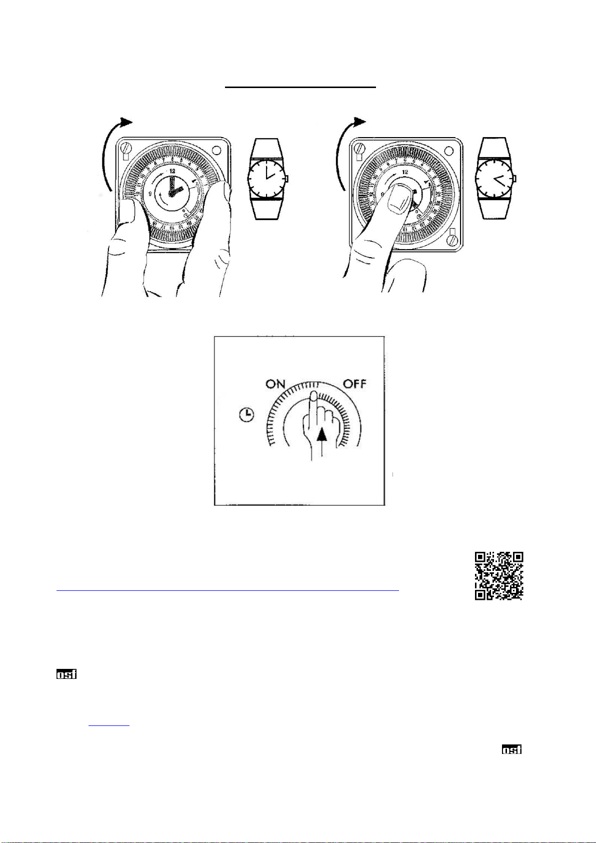
The Pool Master 400 filter control enables a 400V 3-phase filter pump to be switched on or off in a timed
manner. The time of day and the individual switching periods are set in accordance with the enclosed
operating instructions of the timer. The selection switch on the front cover is used to:
(a)
Switch the function of the system on or off.
CAUTION: this does not isolate all poles of the control from supply!
(b)
Switch the system to continuous operation or automatic operation (timer) of the filter pump.
In addition, during the operating time of the filter pump the heating of the pool is controlled by the electronic
temperature control. The heating is switched off automatically by the internal interlocking during filtering
pauses. An adjustment control on the front cover can be used to select the desired temperature of the
swimming pool water or turn the heating off.
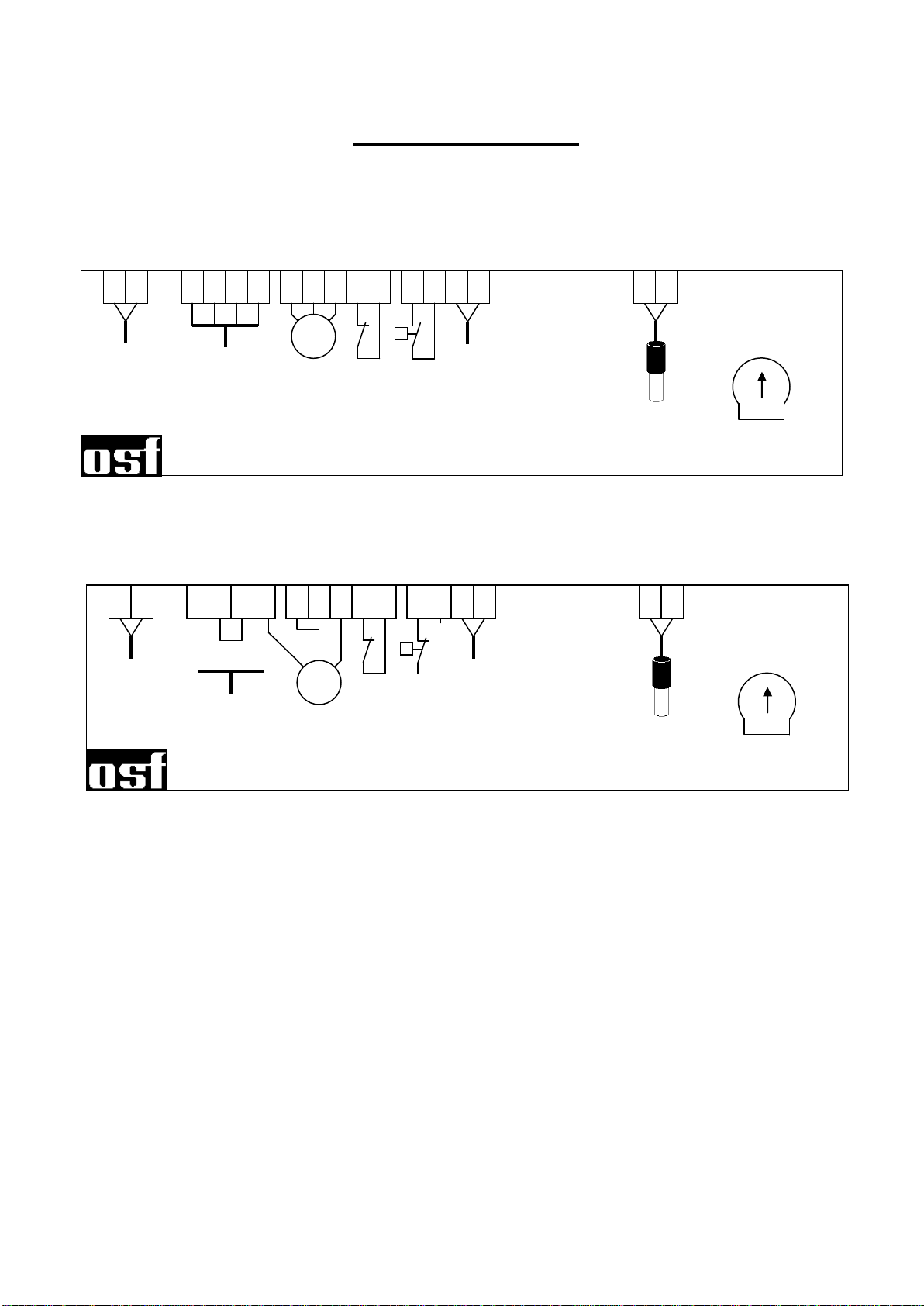
Another terminal enables accessories to be connected, e.g. feeders. The terminals D/D are floating contacts
and can therefore be used as needed. The relay contact between the terminals D/D is closed during the
filtering times and open outside the filtering times. Currents of up to 230V and outputs of up to 400W (cos
=1) can be put on this contact.
The terminals for the motor winding protection contact (WSK) enable a motor winding protection contact
switch to be connected, which is integrated into the motor winding of the filter pump. If this contact opens, e.g.
as result of the motor winding becoming excessively hot, the filter pump and with it the heading and the feeder
are switched off automatically as well. As soon as the motor winding protection contact closes after the motor
has cooled down, the units will switch on again automatically. A manual reset is not necessary. The terminals
WSK are allocated 230V.
Control lamps in the front cover indicate that the filter pump and the heating are operating, enabling
verification to be made at any time.
The filter pump is protected from overload by an electronic motor protection (current range infinitely variable
up to 8A).
Technical data:
Dimensions:
220mm x 219mm x 100mm
Operating voltage:
400V/50Hz
Power consumption of control system:
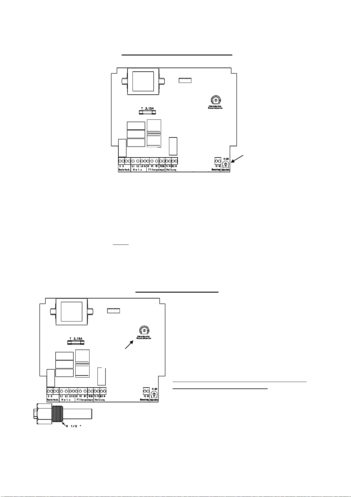
approx. 5VA
Switching capacity:
Pump:
max. 3,0 kW (AC3)
Heating:
max. 0,4 kW (AC1)
Protection class:
IP 40
Installation:
The control unit must be installed protected from moisture in accordance with its protection class. The ambient
temperature during operation may be between 0°C and 40°C and should be as constant as possible. The rel.
Humidity at the installation location must not exceed 95%. Condensation must not occur. Direct heat or solar
radiation to the device should be avoided. The power supply of the unit must be connected via an all-pole
main switch with a contact gap of at least 3 mm and an earth leakage protection switch with IFN30mA.
The unit must be isolated from supply before opening the case.

Operating manual Pool-Master 400 Page: 2
Electrical connection:
The electrical connection, and adjustment work and service may only be carried out by an
approved electrician! The following terminal diagram and the currently applicable safety
regulations must be observed.
When using a 400V three-phase current pump:
When using a 230V alternating current pump:
This control is not suitable for the connection of a filter pump with speed control. For such pumps we have
other controls in our product range
The bridge between the two terminals labelled WSK inserted at the factory must be removed when connecting
a motor winding protection contact. If no connection is made, it must be left screwed in place.
A floating contact for connecting the feeder is provided at terminals D/D. This contact is always closed when
the filter pump is operating.
A 2A fine-wire fuse in the terminal box protects the electronic control together with the heating.
NTC
water
temp.
sensor
Pool Master 400
Filter pump
400V
max. 8A
Dosing control
floating contact
max. 8A
L1
L2
L3
N
Mains
3/N/PE
400V 50Hz
15
16
U1
W1
V1
WSK
Th
Th
U2
N
D
D
heater
max 400W
M
3~
winding
protection
contact
safety
temperature
limiter
motor protection
NTC
water
temp.
sensor
Pool Master 400
Filter pump
230V
max. 8A
Dosing control
floating contact
max. 8A
L1
L2
L3
N
Mains
1/N/PE
230V 50Hz
15
16
U1
W1
V1
WSK
Th
Th
U2
N
D
D
heater
max 400W
M
1~
winding
protection
contact
safety
temperature
limiter
motor protection

Operating manual Pool-Master 400 Page: 3
Electronic motor protection:
The 3-phase filter pump is protected from damage resulting from overload by an electronic motor protection.
To do so the motor protection needs to be set to the nominal current of the filter pump (see name plate of the
pump). If the nominal current of the filter pump is not know, the motor protection can be set using the following
procedure:
1. Turn the adjustment screw of the motor protection in the terminal box clockwise up to the stop.
2. Switch the pump on
3. Turn the adjustment screw slowly counter clockwise until the motor protection trips and the red fault
message comes on.
4. Turn the adjustment screw clockwise by some degrees (approx. 10%).
5. Release the motor protection with the black key: the fault message goes off and the filter pump runs.
Temperature control:
The electronic temperature control and the temperature
detector have been aligned to each other at the factory.
If the detector is replaced, a new alignment can be made
using a potentiometer inside the equipment. If, due to an
unsuitable installation position of the temperature
detector, the water temperature does not match the
desired temperature, this can also be adjusted using the
same potentiometer.
The temperature detector is supplied with a 1.5m cable
as standard. If required this can be extended up to 20m.
To rule out interference avoid installing the detector
cable in the vicinity of supply cables.
Since an exact temperature control is only performed when there is good
heat transfer between temperature detector and swimming pool water, an
osf immersion sleeve R 1/2 " (product code 3200200001) must be installed
in the pipe system.
Adjust motor protection
Temperature
alignment

Operating manual Pool-Master 400 Page: 4
Operation oft the timer
Set the time
Set switching time
Further information can be found on the Internet at the following address:
https://osf.de/download/documents/doclist.php?device=PM-400&subdir=none
We hope you enjoy relaxing in your swimming pool.
Hansjürgen Meier
Elektrotechnik und Elektronik GmbH & Co KG
Eichendorffstraße 6
D-32339 Espelkamp
E-Mail: info@osf.de
Internet: www.osf.de
Subject to alterations! 06/22
This manual suits for next models
1
Table of contents
Other OSF Water Filtration System manuals
Popular Water Filtration System manuals by other brands

Force of Nature
Force of Nature FON-KIT-001 quick start guide

Applied Membranes
Applied Membranes L Series Operation, maintenance & instruction manual

Oase
Oase BioSmart 5000 operating instructions

ACO
ACO Lipumax-P installation guide

Weq
Weq CFW320-KFA Installation, configuration and operations guide

Teka
Teka Spark operating instructions