Oshkosh JERR-DAN 21RRSB-W User manual

Product Manual
Towing & Recovery Carrier
August 2019
5-376-000209 Rev F © 2019 Jerr-Dan Corporation. All Rights Reserved
13224 Fountainhead Plaza
Hagerstown, MD 21742
Phone (717) 597-7111
www.jerr-dan.com


Towing & Recovery Carrier Product Manual - Page 4
Jerr-Dan Corporation strives to provide information that is accurate, complete and
useful. Descriptions and illustrative material contained within this manual are as
accurate as known at the time of publication and are subject to change, without
notice, as a result of continuous product improvements. Jerr-Dan reserves the
right to amend the information in this document at any time without prior notice.
Please report comments and/or errors by contacting Jerr-Dan Corporation’s
Technical Publications Department by e-mail at technical publications@jerr-dan.
com or by FAX on 717-485-7162.
Manufactured under one or more of the following patents: 5,133,633; 5,697,741;
5,951,235; 6,315,515 B1; 6,447,239 B2; 5,575,606; 5,722,810; 6,231,294 B1;
6,336,783 B1; 7,264,305 B2 with other Patents Pending.
Jerr-Dan and the Jerr-Dan logo, Galvanized Steel Beam Technology™, R.A.I.L™
System (Rear Awareness Indicator Lights), Actuated Remote Mechanism (ARM™),
SRS™ (Side Recovery System) and No-Lube™ are registered trademarks and Run
Hard is a service mark of Jerr-Dan Corporation, Hagerstown, MD USA.
The material in this document is condential and the property of Jerr-Dan
Corporation. No part of this document may be photocopied, reproduced or
translated to another language without the express written consent of Jerr-Dan
Corporation.
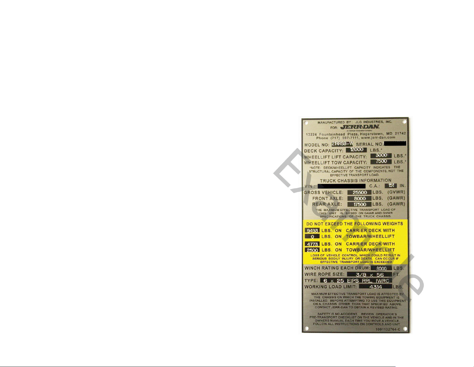
Structural Tow Application Rating (STAR) PLACARD
●Jerr-Dan provides a STAR placard with each new Standard
Duty Carrier. The placard is placed on all headboards.
●This placard serves as a reference to the load weights that the
operator’s carrier can handle based on load ratings.
●The data used to calculate these important weights are specic
to each chassis and the options they are equipped with.
●As of August 2016 the STAR placard is exclusive to Jerr-Dan.

Towing & Recovery Carrier Product Manual - Page 5
Table of Contents
Revision Changes 5
Standard Duty Chassis Requirements 6
Single Axle Critical Chassis Measurements 7
Tandem Critical Chassis Measurements 8
Hydraulic Tank & Flexible Hose Tracking System 9
Special Paint Options 10
Standard Duty 6-Ton XLP Carrier Spec Sheet 11
Standard Duty 6-Ton Carrier Spec Sheet 12
Standard Duty & XLP Carrier Load Angles on Conventional Decks 13
Standard Duty & XLP Carrier Load Angles on Dual Angle Decks 14
Deck Surface Types 16
Standard Duty Steel Conventional, Dual Angle Deck Comparison & Rails 17
Standard Duty Steel Deck Specs 18
Standard Duty Aluminum Conventional, Dual Angle Deck Comparison & Rails 19
Standard Duty Aluminum Deck Specs 20
Standard Duty Wheel Lifts & Accessories 21
Standard Duty Stabilizers 22
Medium Duty Chassis Requirements 23
Medium Duty Single Winch Deck Comparison 24
Medium Duty Dual Winch Deck Comparison 25
Medium Duty Wheel Lifts & Accessories 26
Medium Duty Wheel Lift Accessories 27
Medium Duty Stabilizers 28
Heavy Duty Chassis Requirements 29
10 & 15 Ton Deck Comparison 30
Steel Deck Options 31
Heavy Duty Winch Options 32
Heavy Duty Wheel Lifts & Accessories 33
Heavy Duty Stabilizers 34
Deck Options 35
Winch 36
Winch Options 37
Headboards 38

Towing & Recovery Carrier Product Manual - Page 6
Table of Contents
Headboard Options 39
SRS (Side Recovery System) Spec Sheet 41
SRS Options 42
Tow Hitch Options 43
Lighting Options 44
Switch Panel Options 46
Remote Control Options 47
Storage Options 48
Hydraulic Tank Mounting Brackets 50
Miscellaneous Towing Options & Accessories 51

Towing & Recovery Carrier Product Manual - Page 7
Revision Changes
●Revision B - Corrected Deck Weights to include Decking and Deck Structure
●Revision C - Updated Pictures of Chain Racks
●Revision D - Added Deck Surface Types, Added Carrier Load Angles, Hydraulic Tank Information, Tracking System and additional
Deck Information, Removed 8K Planetary Winch, Added Back up Camera & Review Mirror, Anti-slip Paint on deck
●Revision E - Updated Chassis Requirments for all Carriers with new Maximum Tire Height Above Frame Rails measurment
●Revision F - Updated Weights on Chassis Option Items, Updated Chassis Specs to include CV515 and Chevy 5500HD / 6500HD.

Towing & Recovery Carrier Product Manual - Page 8
Standard Duty Chassis Requirements
RBM Minimum
(Resis�ng Bending Moment)
Carriers without tuohtiwsreirraCnoitpotfil-leehW Wheel-liopon
Carriers withhtiwsreirraCnoitpotfiL-leehWbl0003 3500 lb Wheel-Liopon
BAClanoitiddAmuminiMnoitpokceDtf02noitpokceDtf91 ehind Cab
noitpokceDtf12noitpokceDtf02
noitpokceDtf22noitpokceDtf12
aoLlamitpOrofthgieHemarFelgnAdaoLlamitpOrofthgieHemarF egnaRthgieHemarFelgnAd
Maximum Tire Height Above Frame Rails
(Air Suspension Dumped orSprings
Laden)
Maximum Tire Height Above Frame Rails
(Air Suspension Dumped orSprings
Laden)
emarFretf
AmuminiMemarFretfAmuminiM
4. For 102" wideNGAR with overall re tread width narrower than 94.88", an addional 4.00"of re height above framerailsis allowable.
5. For 102" wideNGAF with overall re tread width narrower than 97.50", an addional 3.50"of re height above framerailsis allowable.
6. For 102" wideRRSB with overall re tread width narrower than 94.63", an addional 3.50"of re height above framerailsis allowable.
7. For 102" wide STRB/NGAT with overall re tread width narrower than 94.63", an addional 2.25"of re height above frame railsis allowable.
Disclaimer: Jerr-Dan makes no guarantee that meeg the above requirements will ensure a carrier body will t on the specied chassis.
1. Modular Staonary Headboard requires addional 12" of clean CA behind the cab. (Replaces Fixed Height Staary Headboard which required only6"of addional clean CA.)
2. Isuzu NRR and Hino 195 requires a minimum aer frameof 40"
3. Useable CA for Jerr-Dan Carriers is deed as the availableclear space beind the cab and above the frame rails, measured from the rear most obstrucon to the center of the rear axle.
Usable CA1, 3
(Back of Cabto Centerline
of Rear Axle)
36"
2
36"
2
N/A
Miscellaneous
Requirements
NGAR - 4.25"
RRSB - 4.25"
NGAF - 4.75"
STRB - 5.25"
NGAT - 6.00"
NGAR - 2.00"
RRSB - 2.00"
NGAF - 2.50"
N/A
138” through 150” N/A
132” through 144”
"24-"23"43-"92
N/A
144” through 156”
12" (Clean Frame)
Chassis Requirements
Std Height & Transporter Models
All applicas
GVWR Minimum
(Gross Vehicle Weight Ra�ng)
19,500 lbs Total
(13,500 lbs Rear)
noitpOSRSsledoMPLX
1,000,000 (in-lb)
(500,000 per rail)
1,000,000 (in-lb)
(500,000 per rail)
900,000 (in-lb)
(450,000 per rail)
31" - 34"
15,000 lbs Total
(11,000 lbs Rear)
19,500 lbs Total
(13,500 lbs Rear)
120” through 132”120” through 126”
126" through 138"
15,000 lbs Total
(11,000 lbs Rear)
19,500 lbs Total
(13,500 lbs Rear)

Towing & Recovery Carrier Product Manual - Page 9
Single Axle Critical Chassis Measurements
CA
BBC CF
AF
Frame
Height
Cab
Height
Max Tire Height
WBBFA
OAL
GVWR
Abbreviation Measurement Denition
AF After Frame Distance from center line of rear axle to end of frame
BBC Bumper to Back of Cab Distance from front bumper to back of cab
BFA Bumper to Front Axle Distance from Front of bumper to center line of front axle
CA Cab to Axle Distance from back of cab to center line of axle
CF Cab to Frame Distance from back of cab to end of frame
OAL Overall Length Total length of the vehicle
WB Wheel Base
The distance between the center lines of the front and rear axles.
For vehicles with tandem rear axles, the center line is midway
between the two rear axles.
Max Tire Height Max Tire Height
Maximum Tire Height Above Frame Rails
(Air Suspension Dumped or Springs
Laden)

Towing & Recovery Carrier Product Manual - Page 10
Tandem Critical Chassis Measurements
CT
BBC CF
AF
Frame
Height
Cab
Height Max Tire Height
WB
BFA
OAL
GVWR
Abbreviation Measurement Denition
AF After Frame Distance from center line of rear axle to end of frame
BBC Bumper to Back of Cab Distance from front bumper to back of cab
BFA Bumper to Front Axle Distance from Front of bumper to center line of front axle
CT Cab to Tandem Distance from back of cab to center line of tandem axle
CF Cab to Frame Distance from back of cab to end of frame
OAL Overall Length Total length of the vehicle
WB Wheel Base
The distance between the center lines of the front and rear axles.
For vehicles with tandem rear axles, the center line is midway
between the two rear axles.
Max Tire Height Max Tire Height
Maximum Tire Height Above Frame Rails
(Air Suspension Dumped or Springs
Laden)

Towing & Recovery Carrier Product Manual - Page 11
Hydraulic Tank & Flexible Hose Tracking System
●Hydraulic tank is mounted on the outside of the truck frame
◦ Easy access to check and ll hydraulic tank
◦ Sight gauge located on tank to check uid levels and color
◦Pressure gauge located on tank
●2 outboard tilt cylinders are used to provide stability
●Hoses and wiring are in a exible tracking system located in the subframe
◦Protects hoses and wiring from snagging and debris
◦ Track system can be retrot into older units

Towing & Recovery Carrier Product Manual - Page 12
Special Paint Options
STATIONARY
HEADBOARD VIEW
GENERIC CARRIER VIEW
SRS VIEW
Group 5
Headboard / Pylon
Group 5
Headboard / Pylon
Group 44
SRS Sheaves
Group 41
SRS Swing Arm
Group 47
SRS Subframe
Group 45
SRS Spade Legs
Group 5
Headboard / Pylon
Group 1
Deck (Steel Deck Only)
Group 20
Deck Winch
Group 17
Wheel Lift Grid
Group 2
Removable Rails
(Steel Rails Only)
Group 14
Wheel Lift / Dock Stabilizer
Group 7
Subframe
Group 6
Push Bumper
Group 48
SRS Winch
Group 8
Stationary Headboard Base
Group Description Special Paint Color
#
1
2
5
6
7
8
14
17
20
34
41
44
45
47
Steel
Only
Aluminum or Steel
48
Deck
Removable Rails
Headboard / Pylon
Push Bumper ( Optional)
Subframe
Stationary Headboard Base
Wheel Lift W/ Stabilizer
Wheel Lift Grid
Deck Winch
Upper Deck Winch
SRS Swing Arm
SRS Sheaves
SRS Spade Legs
SRS Subframe
SRS Winch
Standard Color for all
groups is Black

Towing & Recovery Carrier Product Manual - Page 13
Standard Duty 6-Ton XLP Carrier Spec Sheet
Features
●Load angles as low as *7.5°
●Lowest maintenance carrier in the world including No-
Lube™ technology for slide pads and pivot joints
●Industry’s strongest aluminum bed featuring exclusive,
Patented Galvanized Steel Beam Technology™
Technology
●On-board hydraulic pressure gauges assists with troubleshooting
●Single sheet decking on conventional & dual angle steel deck
reduces weld joints & potential corrosion points
●Combination winch cable guide roller/tensioner plate
●Manual or air-controlled winch-free spool
●Dual manual free spool
●Corrosion-resistant lightened dual control stations
●Federal Motor Carrier Safety Administration DOT
393 compliant crash protection headboard
●Most advanced, high performance hose/wire cable-
tracking system in the industry
●Highest standard DOT reectivity and lighting levels in the industry
●12 key slots standard
◦2 Front of deck, 6 Mid-Deck, 4 Rear of deck
Accessories
●Exclusive R.A.I.L™ System (Rear Awareness Indicator Lights)
●Industry’s strongest and most user-friendly SRS™ (Side Recovery System)
●Wireless remote with exclusive ARM™ (Actuated Remote Mechanism) system
●LED emergency lighting
●Multiple work light mounting locations
●36”, 48”, 60” & 78” toolboxes, storage trays and baskets
●Automatic throttle-up on-demand (subject to chassis conguration)
●Galvanized sub frame and wheel lift components
* Minimum load angle achieved with dual-angle deck on air-ride chassis with air bags
deated.
Deck
●Length: 20’, 21’, 22’
●Capacity: 12,000 lbs
●Width: 96”, 102”
●Style
◦Steel
-Conventional or dual angle
-3/16” diamond or smooth decking
-Fixed or removable tubular side rails
-Removable blade side rails
◦Aluminum
-Conventional or dual angle
-Extruded 6061-T6 decking
-Fixed or Removable blade side rails
●Winch:
◦8,000 lb with 3/8” x 56’ wire rope
◦10,000 lb with 7/16” x 56’ wire rope
Wheel Lift
●Lift Capacity: 3,500 lbs
●Tow Capacity: 10,000 lbs
●Maximum Extended Reach: 68”
●Grounded Approach Angle: 3°
Chassis
●Minimum RBM (Resisting Bending Moment)
◦1,000,000 in-lbs (500,000 in-lbs. per frame rail)
●Usable CA (Cable to Axle Center line)
◦120”–132” (20’ deck)
◦132”–144” (21’ deck)
◦144”–156” (22’ deck)
●Optimal Load Angle Frame Height: 29”-34”
●Minimum GVWR (Gross Vehicle Weight Rating)
◦With wheel lift 19,500 lbs total (13,500 lbs rear)
◦Without wheel lift 15,000 lbs total (11,000 lbs rear)

Towing & Recovery Carrier Product Manual - Page 14
Standard Duty 6-Ton Carrier Spec Sheet
Features
●Lowest maintenance carrier in the world including No-
Lube™ technology for slide pads and pivot joints
●Industry’s strongest aluminum bed featuring exclusive,
Patented Galvanized Steel Beam Technology™
●On-board hydraulic pressure gauge assists with troubleshooting
●Single sheet decking on conventional & dual angle steel
decks reduces weld joints & potential corrosion points
●Combination winch cable guide roller/tensioner plate
●Manual or air controlled winch free-spool
●Corrosion resistant lighted dual control stations
●Federal Motor Carrier Safety Administration DOT
393 compliant crash protection headboard
●Most advanced, high performance hose/wire cable-
tracking system in the industry
●Highest standard DOT reflectivity and lighting levels in the industry
●12 key-slots standard
◦2 Front of deck, 6 Mid-Deck, 4 Rear of deck
●Available on a wide range of domestic & foreign chassis
Accessories
●Exclusive R.A.I.L™ System (Rear Awareness Indicator Lights)
●Industry’s strongest and most user-friendly SRS™ (Side Recovery System)
●Wireless remote with exclusive ARM™ (Actuated Remote Mechanism) system
●LED emergency lighting
●Multiple work light mounting locations
●36”, 48”, 60” & 78” toolboxes, storage trays and baskets
●Automatic throttle-up on-demand (subject to chassis conguration)
●Galvanized sub frame and wheel lift components
Wheel Lift
●Lift Capacity: 3,000 lbs
●Tow Capacity: 7,500 lbs
●Maximum Extended Reach: 63”
●Grounded Approach Angle: 4°
Deck
●Length: 19’, 20’, 21’
●Capacity: 12,000 lbs
●Width: 96”, 102”
●Style
◦Steel
-Conventional or dual angle
-3/16” diamond or smooth decking
-Fixed or removable tubular side rails
-Removable blade side rails
◦Aluminum
-Conventional or dual angle
-Extruded 6061-T6 decking
-Fixed or removable blade side rails
●Winch:
◦8,000 lb with 3/8” x 56’ wire rope
◦10,000 lb with 7/16” x 56’ wire rope
Chassis
●Minimum RBM (Resisting Bending Moment)
◦1,000,000 in-lbs (500,000 in-lbs per frame rail)
●Usable CA (Cable to Axle Center line)
◦120”–126” (19’ deck)
◦126”–138” (20’ deck)
◦138”–150” (21’ deck)
●Optimal Load Angle Frame Height
◦31”–34”
●Minimum GVWR (Gross Vehicle Weight Rating)
◦With wheel lift 19,500 lbs total (13,500 lbs rear)
◦Without wheel lift 15,000 lbs total (11,000 lbs rear)

Towing & Recovery Carrier Product Manual - Page 15
Standard Duty & XLP Carrier Load Angles of Decks
Standard Duty
Carrier
11.0°- 13.0°
Standard Duty Carrier With Dual Angle Deck
9.0°- 11.5°
XLP Carrier
9.0°- 12.0°
XLP Carrier With Dual Angle Deck
7.5°- 10.0°

Towing & Recovery Carrier Product Manual - Page 16
Sub Frame Accessories
Add Greasable Feature to any Sub Frame and/or Wheel Lift Combination
●Greased Pivot Joint Option Sub Frame Only
◦Item: 1001210267
●Greased Pivot Joint Option Sub Frame & Wheel Lift
◦Item: 1001207209

Towing & Recovery Carrier Product Manual - Page 17
Deck Surface Types
12 Key-Slots Standard
●Diamond Decking is Standard

Towing & Recovery Carrier Product Manual - Page 18
Standard Duty Steel Conventional, Dual Angle Deck Comparison
Dual Angle
Dimension Smooth Diamond CA (SD) CA (XLP)
19’ x 96” 2,990 lbs 3,135 lbs 120”-126” N/A
19’ x 102” 3,105 lbs 3,255 lbs 120”-126” N/A
20’ x 96” 3,105 lbs 3,255 lbs 126”-138” 120”-132”
20’ x 102” 3,220 lbs 3,380 lbs 126”-138” 120”-132”
21’ x 96” 3,220 lbs 3,375 lbs 138”-150” 132”-144”
21’ x 102” 3,335 lbs 3,505 lbs 138”-150” 132”-144”
22’ x 96” 3,335 lbs 3,500 lbs N/A 144”-156”
22’ x 102” 3,445 lbs 3,630 lbs N/A 144”-156”
Conventional
Dimension Smooth Diamond CA (SD) CA (XLP)
19’ x 96” 2,835 lbs 2,980 lbs 120”-126” N/A
19’ x 102” 2,950 lbs 3,100 lbs 120”-126” N/A
20’ x 96” 2,940 lbs 3,165 lbs 126”-138” 120”-132”
20’ x 102” 3,055 lbs 3,215 lbs 126”-138” 120”-132”
21’ x 96” 3,040 lbs 3,195 lbs 138”-150” 132” - 144”
21’ x 102” 3,155 lbs 3,325 lbs 138”-150” 132” - 144”
22’ x 96” 3,140 lbs 3,310 lbs N/A 144”-156”
22’ x 102” 3,255 lbs 3,440 lbs N/A 144”-156”
*Deck Weight is conventional deck without removable rails
Removable Steel Tubular Rails
Removable Blade Rails
*Deck Weight is dual angle deck with removable blade rails

Towing & Recovery Carrier Product Manual - Page 19
Standard Duty Steel Deck Specs
5" HIGH REMOVABLE TUBULAR STEEL
5" HIGH REMOVABLE BLADE ALUMINUM
6" HIGH PERMANENT TUBULAR STEEL
100"(102 DECK)
94"(96DECK)
5.00
RAISED RAIL
6.00
RUBRAIL
0.44
96" (102 DECK)
90" (96 DECK)
5.00
RAISEDRAIL
6.00
RUBRAIL
0.96
0.52
97" (102DECK)
91"(96 DECK)
6.00
RAISED RAIL
6.00
RUBRAIL
0.38

Towing & Recovery Carrier Product Manual - Page 20
Standard Duty Aluminum Conventional, Dual Angle Deck Comparison
Dual Angle
Dimension Weight (lbs.) CA (SD) CA (XLP)
19’ x 96” 1,700 lbs 120”-126” N/A
19’ x 102” 1,745 lbs 120”-126” N/A
20’ x 96” 1,770 lbs 126”-138” 120”-132”
20’ x 102” 1,815 lbs 126”-138” 120”-132”
21’ x 96” 1,840 lbs 138”-150” 132”-144”
21’ x 102” 1,885 lbs 138”-150” 132”-144”
22’ x 96” 1,910 lbs N/A 144”-156”
22’ x 102” 1,955 lbs N/A 144”-156”
Conventional
Dimension Weight (lbs.) CA (SD) CA (XLP)
19’ x 96” 1,700 lbs 120”-126” N/A
19’ x 102” 1,745 lbs 120”-126” N/A
20’ x 96” 1,770 lbs 126”-138” 120”-132”
20’ x 102” 1,815 lbs 126”-138” 120”-132”
21’ x 96” 1,840 lbs 138”-150” 132” - 144”
21’ x 102” 1,885 lbs 138”-150” 132” - 144”
22’ x 96” 1,910 lbs N/A 144”-156”
22’ x 102” 1,955 lbs N/A 144”-156”
*Deck Weight is conventional deck with xed rails*Deck Weight is dual angle deck with xed rails
Fixed Rail
Removable Blade Rail
Table of contents
Popular Industrial Equipment manuals by other brands

Argus
Argus ALPHA OUTBACK ENERGY Cordex 48-1kW instruction manual

Zionair
Zionair SB120A Assembly and user instructions

Lenze
Lenze PROFIBUS-DP Communications manual

Aventics
Aventics R434001024 Service information

Mayr
Mayr EAS-NC Lastic-Backlash-free Installation and operational instructions

Nakanishi
Nakanishi NR3060-AQC Operation manual