OSI Systems Rapiscan Metor 6E User guide

Rapiscan Systems 1 (1)
Printing instructions_A4.doc
DO NOT PRINT THIS PAGE
PRINT FOLLOWING DOCUMENT AS:
2-SIDED COLOR PRINTING
FORMAT A5 ON A4 BOOKLET
FOLD AND STAPLE AT CENTER
DO NOT PRINT THIS PAGE

Installation Quick Guide
Metor 6E
P/N 92109435 – Rev. 2

Page 2 Metor 6E P/N 92109435
Installation Quick Guide Rev. 2
Rapiscan Systems Proprietary Information
Foreword
Thank You for choosing a Metor product. This installation quick guide is intended for experienced users that
are fully trained on the operation of Metor Walk-Through Metal Detectors. In addition to these instructions,
local laws and regulations, and requirements by authorities shall be observed.
The user should read also the Installation and Operating Manual supplied on a CD ad understand its
contents before the installation or use of the equipment.
Copyright Notice
The owner or authorized user of a valid copy of the products covered by this manual may reproduce this
publication only for the purpose of learning to use such product. No part of this publication may be
reproduced or transmitted for any other purpose, such as selling copies of this publication or providing paid-
for support services.
© Rapiscan Systems. All rights reserved.
Content of this Manual
We have made an effort to ensure that the information in this manual is accurate as of the date of
publication. However, the product that you have purchased may contain options, upgrades or modifications
not covered by this manual.
If you have any questions about the content of this manual or the product that you have purchased, please
contact Rapiscan Systems Customer Service.
No Warranties
The provision of this manual to you creates no express or implied warranties of any kind, including, without
limitation any warranties with respect to the accuracy, applicability, completeness or fitness of this manual for
any particular purpose.
Limitation on Liability and Warranty
Rapiscan systems will not accept liability for damage or personal injury caused directly or indirectly by either
incorrect or poor quality termination of the local main power supply or power cables. Rapiscan Systems is
not responsible for damage or injury caused by unauthorized modification, maintenance, operation or
tampering with this equipment.
Rapiscan Systems will not be liable for any indirect, special, incidental or consequential damage, including
loss of profit. Rapiscan Systems disclaims liability for any express or implied warranty of merchantability or
fitness of the product for a particular purpose.
Any modification or alteration made to the system after purchase by the customer or their agents without
written authorization from Rapiscan Systems Service Department Management will void any warranty issued
to the customer. Additionally, Rapiscan Systems is not liable for any damage that might be caused by any
unapproved changes or modifications.
P/N 92109435 Metor 6E Page 3
Rev. 2 Installation Quick Guide
Rapiscan Systems Proprietary Information
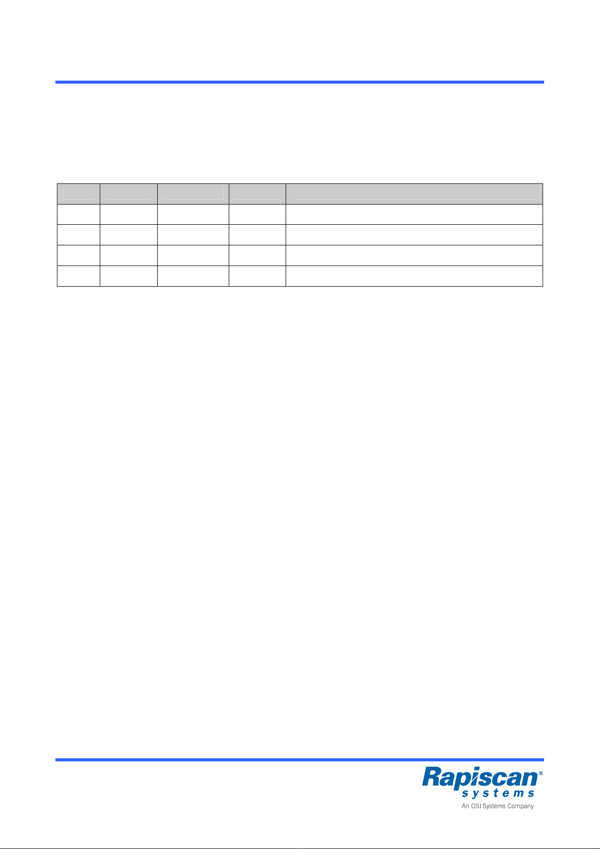
Revision History
Name of Document: Installation Quick Guide, Metor 6E
Document Number: 92109435, Revision 2
Rev. ECN # Date Name Comments
A 2013-05-20 TV Initial draft.
B 2013-06-06 TV Several additions.
1 03829 2013-06-28 TV Release version.
2 04550 2013-10-14 TV DC symbol added.

Page 4 Metor 6E P/N 92109435
Installation Quick Guide Rev. 2
Rapiscan Systems Proprietary Information
Table of Contents
1IMPORTANT INSTRUCTIONS........................................................................................................5
1.1 Types of Alert Messages.......................................................................................................6
1.2 Symbols used on Unit and in Manual....................................................................................6
2TECHNICAL DATA..........................................................................................................................7
3INSTALLATION ...............................................................................................................................8
3.1 Mechanical Assembly............................................................................................................8
3.2 Floor Fixing..........................................................................................................................10
3.3 Electrical Connections.........................................................................................................11
3.4 Connections for Digital I/O ..................................................................................................12
4STARTUP AND SHUTDOWN.......................................................................................................13
5MAINTENANCE.............................................................................................................................14
5.1 Periodic Maintenance..........................................................................................................14
5.2 Replacing Input Fuse ..........................................................................................................14
5.3 Replacing Battery................................................................................................................14
APPENDIX A: Contact Information.......................................................................................................15

P/N 92109435 Metor 6E Page 5
Rev. 2 Installation Quick Guide
Rapiscan Systems Proprietary Information
1 IMPORTANT INSTRUCTIONS
Read through this chapter carefully before operating the equipment. Keep this manual
so that it is always readily available to the user.
The instructions in this manual shall be followed in all situations, when installing,
using, or servicing the equipment. Rapiscan Systems cannot be held responsible for
any personal or material damage caused by use contradicting the instructions given in
this manual.
All safety regulations must be observed. A dangerous or unsafe manner of operation
may be a health risk.
Installation may only be carried out by qualified person.
Before installing, operating or servicing the equipment, make sure that it poses no risk
of personal or material damage.
Be aware that although the walk through metal detector unit is heavy it may fall down if
a heavy force collides with it. To eliminate the risk of overbalancing the WTMD must be
attached (anchored) on the floor.
Do not operate the equipment unless you are fully trained to do so. The operator must
know the use, service, and safety instructions of the equipment, and local safety
regulations.
Service of Rapiscan products shall be preformed only by a Rapiscan Systems qualified
service provider or authorized contractor qualified service provider. Make sure that
there are no unauthorized persons in the working area when servicing and repairing
the equipment.
It is forbidden to operate the equipment when ill, or under the influence of alcohol or
drugs.
The equipment may not be connected to mains supply until all other connections
necessary for the installation are completed.
The equipment shall always be connected to an earthed socket outlet.
The equipment shall be disconnected from mains supply before servicing, cleaning, or
moving it.
Original Metor spare parts should be exclusively used.
Use a damp cloth for cleaning the equipment. Do not use any chemicals or liquid
detergents.
The end user is responsible for the final calibration of the equipment for the intended
application. It is also the end user’s responsibility to regularly verify calibration to the
desired sensitivity level by using a suitable test object or objects.
If there is any reason to suspect that the security level of the equipment may have
deteriorated due to incorrect operation or external damage, the equipment should be
removed from operation and an authorized service provider should be called in.
Page 6 Metor 6E P/N 92109435
Installation Quick Guide Rev. 2
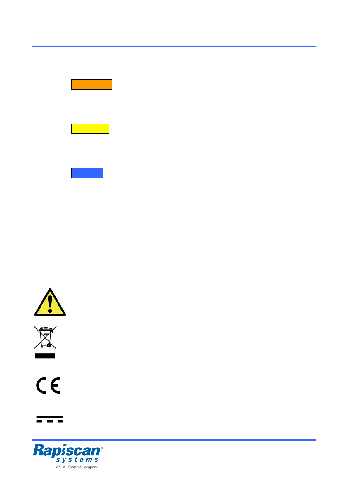
1.1 Types of Alert Messages
WARNING
Indicates a potentially hazardous situation which, if not avoided, could result in death or
serious injury.
CAUTION
Indicates a potentially hazardous situation which, if not avoided, may result in minor or
moderate injury and/or equipment damage or generally unsafe practices.
NOTICE
Indicates an important notice to the reader, that does not necessarily involve the possibility of
personal injury or equipment damage.
All warnings, cautions, notices and instructions presented in this manual should be read and
followed by all personnel who will use or maintain this equipment.
Failure to follow all such warnings, cautions, notices and instructions may result in damage to
the equipment and/or injury or death to personnel. Such failure may also nullify any warranties
provide by the manufacturer.
1.2 Symbols used on Unit and in Manual
General Warning Sign
This sign is used to alert the user to potential hazards. All safety messages that follow this
sign shall be obeyed to avoid possible harm.
Recycling Symbol
This symbol means that according to local laws and regulations this product should not be
disposed of in the household waste but sent for recycling.
CE Symbol
CE marking on a product is a manufacturer’s declaration that the product complies with the
essential requirements of the relevant European health, safety and environmental protection
legislation.
Symbol for Direct Current (DC)
Rapiscan Systems Proprietary Information

P/N 92109435 Metor 6E Page 7
Rev. 2 Installation Quick Guide
Rapiscan Systems Proprietary Information
2 TECHNICAL DATA
Power
Input, nominal...........................................12.5 VDC, 2.1 A
Input, absolute limits ................................12 – 15 VDC, 4 A
Power consumption, typical .....................26 W (12 VDC)
Power consumption, maximum................37 W (12 VDC)
Power consumption, at standby...............11 W (12 VDC)
Ratings of recommended external power supply
Voltage, nominal ......................................100 – 240 VAC
Voltage, absolute limits............................90 – 264 VAC
Frequency, nominal..................................50/60 Hz
Recommended operating conditions
Ambient temperature................................-20 °C – +60 °C / -4 °F – +140 °F
-15 °C – +45 °C / +5 °F – +113 °F,
when battery back-up is in use
Storage temperature................................-30 °C – +70 °C / -22 °F – +158 °F
Relative humidity......................................0 – 95 %, no condensation
Elevation ..................................................max. 3000 m / 9840 ft
Ingress protection rating...........................IP55, excluding external power supply
Pollution degree.......................................2
Page 8 Metor 6E P/N 92109435
Installation Quick Guide Rev. 2
3 INSTALLATION
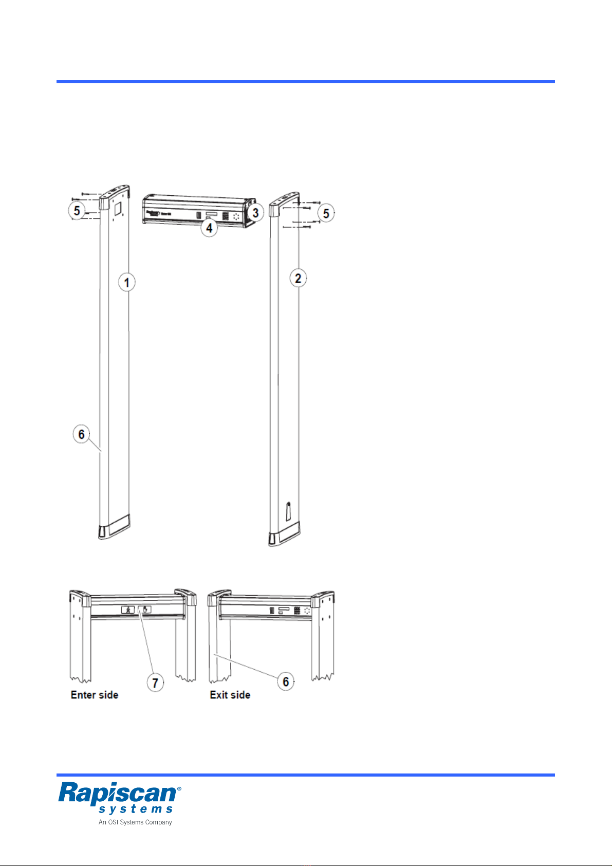
3.1 Mechanical Assembly
The items needed in mechanical assembly
are packed in the box containing the cross
piece.
For checking the distance of the coil panels
there is a pasteboard gauge in the cross
piece box.
Ref Part Pcs
1............Panel 1 (MTRP 5266)..... 1
2............Panel 2 (MTRP 5267)..... 1
3............Cross piece..................... 1
5............Mounting screws............. 8
Washers ......................... 8
Allen key......................... 1
The following parts illustrated in pictures are
integrated into coil panels or cross piece,
but they must be considered in assembly:
Ref Part Pcs
4............Display and keypad........ 1
6............Zone displays ................. 2
(one in each coil panel)
7............Traffic lights .................... 1
Assembly:
First define the sides of the coil panels
if you have side-by-side operation.
Zone displays are assembled at factory
so that they are towards exit side when
panel 2 is on left side and panel 1 on
right side. Position of the displays is
also shown by stickers on the panels.
Lay the coil panels on the floor.
Install the cross piece with display and
keypad towards the exit side.
Place the cross piece to the holes in the
coil panel and fasten using the
mounting screws and washers.
Repeat with the other panel.
Do the final tightening of the screws
after lifting the unit to ensure that the
panels are parallel.
Rapiscan Systems Proprietary Information
P/N 92109435 Metor 6E Page 9
Rev. 2 Installation Quick Guide
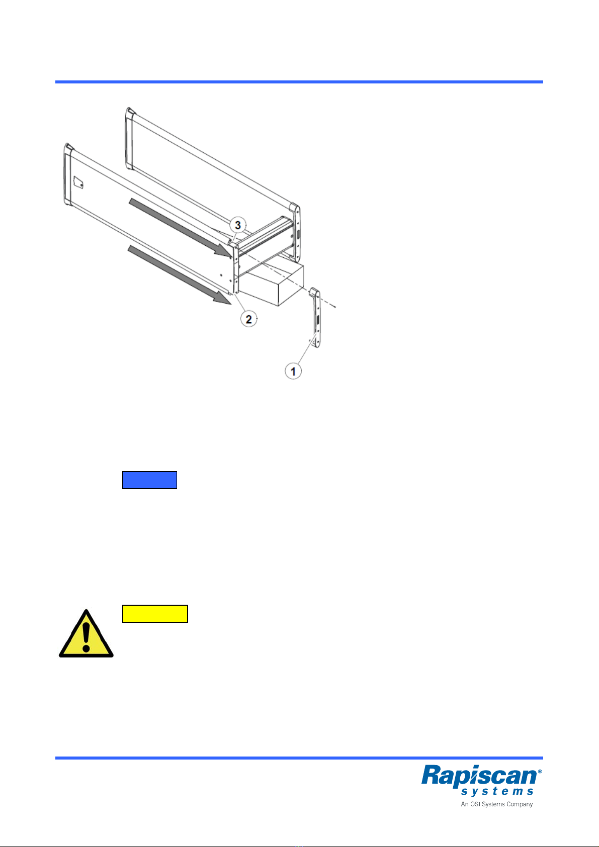
Switching the zone displays to other side
of the coil panels:
Lay the Metor 6E down. Place a support
under the cross piece so that only the
coil panel bottoms touch the ground
(e.g. the cardboard package the cross
piece came in).
Detach the top piece (1) which is held in
position by four screws.
Detach the zone display cable connector
(2) and the counter cable connector (3)
from the top of the tubes.
DO NOT remove the green and red
cables on top of the panel. DO NOT
switch the positions of the cables.
Gently slide out the zone display and
counter tubes to the direction indicated.
Slide the tubes gently in on the opposite
sides of the coil panel.
Reconnect the cables in corresponding
connectors. Check that connectors lock
in position.
Re-install the top piece and fasten it with
the four screws.
DO NOT over tighten the screws as you
may damage the thread in coil panel.
If you are installing an additional zone
display simple remove counter tube and
replace it with the zone display tube.
NOTICE
After changing the side of the zone display you need to select correct zone display
mode from the user interface to enable the zone display using menu “2.4.1 ZONES”.
Refer to chapter 7.4 for further information.
Do not switch zone displays between panels as it will cause counter malfunction. Zone
displays for panel 1 have blue RX stickers on them and displays for panel 2 have red
TX stickers. Same applies to infrared RX/TX counters.
CAUTION
While assembled three persons are recommended for safe lifting and lowering of the
equipment.
Rapiscan Systems Proprietary Information
Page 10 Metor 6E P/N 92109435
Installation Quick Guide Rev. 2
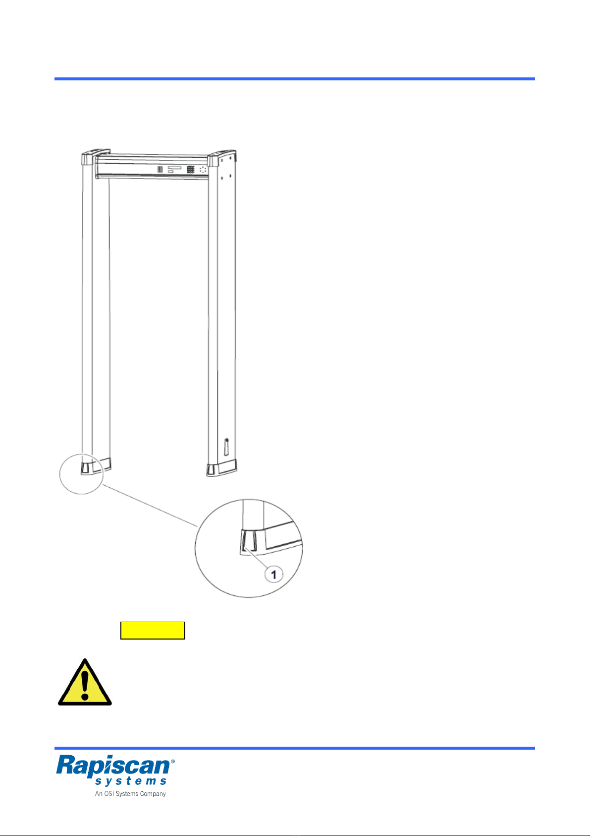
3.2 Floor Fixing
Lift the unit up to a vertical position in its
final mounting location.
Check that the panels are parallel both
in walking direction and sidewise. Use
the pasteboard gauge provided to
ensure that distance between panels is
the same at top and at bottom.
Tighten the mounting screws.
Use the mounting holes (1) in the panel
boots to fix the unit to the floor with
screws.
If drilling holes to the floor is not
preferred you can use the flat areas
under the boots to attach the unit to the
floor with double sided tape or suitable
adhesive.
CAUTION
To eliminate the risk of overbalancing the equipment must be fastened to the floor.
The equipment must be disassembled before carrying by a single person or suitable
carrying equipment must be used. Care must be taken not to overbalance the
equipment when screws are removed from the floor.
Rapiscan Systems Proprietary Information
P/N 92109435 Metor 6E Page 11
Rev. 2 Installation Quick Guide
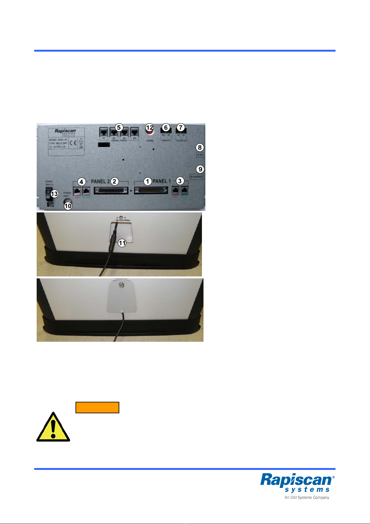
3.3 Electrical Connections
Open cross piece hatch to access connections to the electronics.
Power supply can be connected to either panel. Remove cable hatch of the selected
panel to connect power supply.
Alternatively power supply can be placed over the unit for direct connection to the
electronics through cable gland holes on top of the cross piece.
Connections:
1. Panel 1 coil connector
2. Panel 2 coil connector
3. Panel 1 zone display and counter
connectors (2 pcs)
Note color coding of connections.
4. Panel 2 zone display and counter
connectors (2 pcs)
5. Serial port connections (4 pcs),
all similar, for:
- Display and keypad
- Traffic lights
- MetorNet (option)
- Remote display (option)
6. Digital inputs (2 pcs)
7. Digital outputs (2 pcs)
8. SD memory card slot
9. Ethernet connector
10. DC power input connector
11. Power supply connection under cable
hatch
Switches:
12. LEARN button
13. Power switch
Do not force connections to avoid damaging the contacts.
Panel coil connectors are polarized to avoid misconnections.
Observe color coding when connecting zone display and counter cables.
Display and traffic lights cables can be connected to any of the serial ports.
WARNING
Manufacturer supplied power supply must be used. Do not connect any other power
supply to the DC power cable.
Power supply shall be located to be easily accessible for disconnection.
Rapiscan Systems Proprietary Information
Page 12 Metor 6E P/N 92109435
Installation Quick Guide Rev. 2
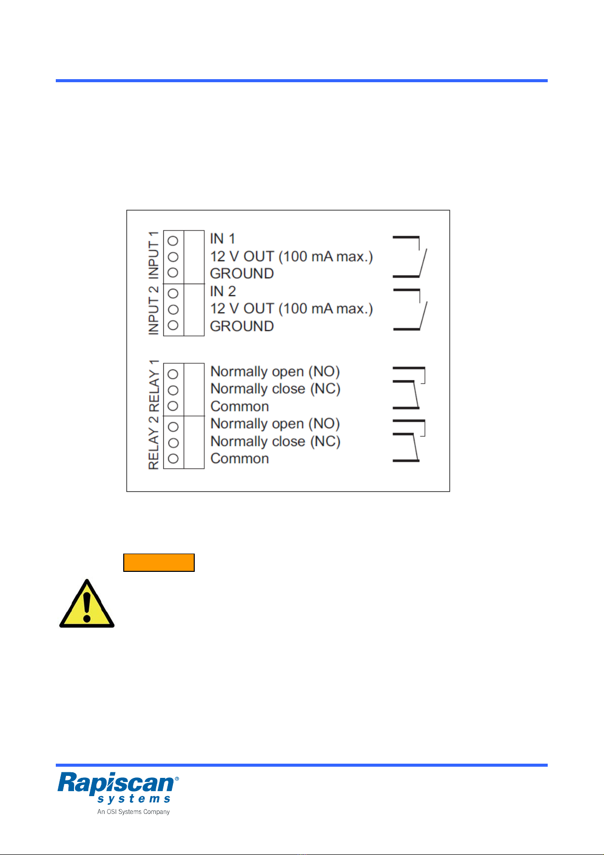
3.4 Connections for Digital I/O
The Metor 6E has two configurable digital inputs and two configurable digital outputs. Refer to
Installation and Operating Mnaual for instructions how to configure the I/O.
The digital inputs have a pull-up resistor to 12 V. Maximum input voltage is 15 VDC.
Recommended connection is a switch that connects input (pin 1) to ground (pin 3).
Maximum load for each relay output is 24 V and 1 A.
WARNING
Line voltage or any circuit connected to line voltage may not be connected to any of
the connectors in the electronics, including the relay outputs. External isolation
circuitry (double/reinforced insulation) must be used if a circuit connected to line
voltage must be controlled.
Rapiscan Systems Proprietary Information

P/N 92109435 Metor 6E Page 13
Rev. 2 Installation Quick Guide
4 STARTUP AND SHUTDOWN
Metor 6E is turned on and off from
the power switch on the main
electronics inside the cross piece.
To access the switch open the cross
piece hatch with the key provided.
The unit can be switched to standby
without the need to open the cross
piece hatch by enabling the standby
feature from the user interface, refer
to chapter 7.7. Standby is turned on
and off with button <C> on the
keypad. During standby all displays
and lights are off and metal detection
is disabled with magnetic field
generation turned off.
After switching on Metor 6E runs a
self-test.
Also all lights are turned on briefly.
During the self-test software versions
of the unit will shown as illustrated on
the left:
- User interface version
- Display unit SW version
- Electronics SW version
In the end selfcheck result is shown.
SW versions may differ from the
ones displayed.
CAUTION
When using the maximum setting for the audible alarm the volume is exceeding 90 dBa
at distances less than 1 m.
Rapiscan Systems Proprietary Information
Page 14 Metor 6E P/N 92109435
Installation Quick Guide Rev. 2
5 MAINTENANCE
5.1 Periodic Maintenance
The Metor 6E is virtually maintenance-free. However, the operation should be checked
regularly, preferably daily, to ensure that the security is not compromised.
For additional information on maintenance please refer to the Maintenance Manual.
5.2 Replacing Input Fuse
Inside the electronics (MELS 5261) there is a 5.0AT fuse F8 protecting the electronics. Fuse
type is Littlefuse Nanofuse 0454005.MR, part number 58105674.
WARNING
Replace fuse only with equivalent type to avoid risk of fire.
5.3 Replacing Battery
Inside the electronics (MELS 5261) there is a CR2032 type 3 V lithium battery that powers the
real time clock while power is off. When battery is empty, the clock resets to January 1, 2010.
Empty battery can also corrupt counter statistics. Typical battery life is over ten years.
WARNING
Replace battery only with equivalent type to avoid risk of fire.
Rapiscan Systems Proprietary Information

P/N 92109435 Metor 6E Page 15
Rev. 2 Installation Quick Guide
Rapiscan Systems Proprietary Information
APPENDIX A: Contact Information
Use these addresses when ordering spare parts and in warranty or repair issues.
E-mail sales@rapiscansystems.com
service@rapiscansystems.com
United Kingdom’s Customer Service Center for Europe, Africa, Mid East
Rapiscan Systems Ltd.
X-ray House
Bonehurst Road
Salfords
Surrey RH1 5GG
UNITED KINGDOM
Tel: +44 (0) 870 777 4301
Fax: +44 (0) 870 777 4302
U.S.A. Customer Service Center for Canada, South America, Caribbean
Rapiscan Systems
2805 Columbia St.
Torrance, CA 90503
USA
Tel: +1 888 258 6684 (toll-free for US customers calling inside USA)
Press #3 Tech Support
Press #5 WTMD
Customer Service Center for Asia, Australia
Warranty and Repair Issues
Rapiscan Systems Sdn. Bhd.
PTD 151290, 6.5km
Jalan Kampung Maju Jaya
Kempas Lama 81300
Skudai, Johor
MALAYSIA
Tel: +60 7 554 7770
Fax: +60 7 554 7772
Spare Part Orders
Rapiscan Systems Pte Ltd.
240 Macpherson Road
#07-03, Pines Industrial Building
Singapore 348574
SINGAPORE
Tel: +65 6846 3511
Fax: +65 6743 9915
Table of contents
Other OSI Systems Medical Equipment manuals


