OSI Systems Spacelabs Medical 90239A User manual

more time to care
Ambulatory Blood Pressure
Report Generator/Printer
90239A
Service Manual
070-0398-00 Rev. D

© 2004 Spacelabs Medical, Inc.
All rights reserved. Contents of this publication may not be reproduced in any form without the written permission of Spacelabs
Medical. Products of Spacelabs Medical are covered by U.S. and foreign patents and/or pending patents. Printed in U.S.A.
Specifications and price change privileges are reserved.
Spacelabs Medical considers itself responsible for the effects on safety, reliability and performance of the equipment only if:
• assembly operations, re-adjustments, modifications or repairs are carried out by persons authorized by Spacelabs
Medical, and
• the electrical installation of the relevant room complies with the requirements of the standard in force, and
• the equipment is used in accordance with the operations manual.
Spacelabs Medical will make available, on request, such circuit diagrams, component part lists, descriptions, calibration instructions
or other information which will assist appropriately qualified technical personnel to repair those parts of the equipment which are
classified by Spacelabs Medical as field repairable.
Spacelabs Medical is committed to providing comprehensive customer support beginning with your initial inquiry through purchase,
training, and service for the life of your Spacelabs Medical equipment.
CORPORATE OFFICES
U.S.A.
Spacelabs Medical, Inc.
5150 220th Ave SE
Issaquah, WA 98029
Telephone: 425-657-7200
Telephone: 800-522-7025
Fax: 425-657-7212
Authorized EC Representative
UNITED KINGDOM
Spacelabs Limited
71 Great North Road, Hatfield
Herts AL9 5EN
Telephone: 44-1707-263-570
Fax: 44-1707-260-065
BirthNet, Data Shuttle, Flexport, Intesys Clinical Suite, Maternal Obstetrical Monitor, MOM, Mermaid, Multiview, PCIS, PCMS,
PrintMaster, Quicknet, Sensorwatch, TRU-CAP, TRU-CUFF, TRU-LINK, UCW, Ultralite, Ultraview, Ultraview Clinical Messenger,
Ultraview SL, Uni-Pouch, Universal Flexport, Varitrend and WinDNA are trademarks of Spacelabs Medical, Inc.
Other brands and product names are trademarks of their respective owners.
CAUTION:
US Federal law restricts the devices documented herein to sale by, or on the order
of, a physician.
Rx
Only

Contents
i
Table of Contents
Introduction
Overview. . . . . . . . . . . . . . . . . . . . . . . . . . . . . . . . . . . . . . . . . . . . . . . . . . . . . . . . . . . . . . . . . . . . . . . . . . . . . . . . . 1-1
Specifications . . . . . . . . . . . . . . . . . . . . . . . . . . . . . . . . . . . . . . . . . . . . . . . . . . . . . . . . . . . . . . . . . . . . . . . . . . . . . 1-1
Control Panel Keys. . . . . . . . . . . . . . . . . . . . . . . . . . . . . . . . . . . . . . . . . . . . . . . . . . . . . . . . . . . . . . . . . . . . . . . . . 1-3
Installation and Set-up
Overview. . . . . . . . . . . . . . . . . . . . . . . . . . . . . . . . . . . . . . . . . . . . . . . . . . . . . . . . . . . . . . . . . . . . . . . . . . . . . . . . . 2-1
Loading Paper . . . . . . . . . . . . . . . . . . . . . . . . . . . . . . . . . . . . . . . . . . . . . . . . . . . . . . . . . . . . . . . . . . . . . . . . . . . . 2-1
Removing Paper. . . . . . . . . . . . . . . . . . . . . . . . . . . . . . . . . . . . . . . . . . . . . . . . . . . . . . . . . . . . . . . . . . . . . . . . . . . 2-1
Power ON Self Test . . . . . . . . . . . . . . . . . . . . . . . . . . . . . . . . . . . . . . . . . . . . . . . . . . . . . . . . . . . . . . . . . . . . . . . . 2-2
Theory of Operation
Input/Output . . . . . . . . . . . . . . . . . . . . . . . . . . . . . . . . . . . . . . . . . . . . . . . . . . . . . . . . . . . . . . . . . . . . . . . . . . . . . . 3-1
Central Processing Unit (CPU). . . . . . . . . . . . . . . . . . . . . . . . . . . . . . . . . . . . . . . . . . . . . . . . . . . . . . . . . . . . . . . . 3-3
Block Diagram . . . . . . . . . . . . . . . . . . . . . . . . . . . . . . . . . . . . . . . . . . . . . . . . . . . . . . . . . . . . . . . . . . . . . . . . . . . . 3-4
Routine Maintenance . . . . . . . . . . . . . . . . . . . . . . . . . . . . . . . . . . . . . . . . . . . . . . . . . . . . . . . . . . . . . . . . . . . . . . . 3-4
Troubleshooting
Main Board/Printer Unit . . . . . . . . . . . . . . . . . . . . . . . . . . . . . . . . . . . . . . . . . . . . . . . . . . . . . . . . . . . . . . . . . . . . . 4-1
Control Panel . . . . . . . . . . . . . . . . . . . . . . . . . . . . . . . . . . . . . . . . . . . . . . . . . . . . . . . . . . . . . . . . . . . . . . . . . . . . . 4-1
Error Messages . . . . . . . . . . . . . . . . . . . . . . . . . . . . . . . . . . . . . . . . . . . . . . . . . . . . . . . . . . . . . . . . . . . . . . . . . . . 4-2
Additional Error Messages . . . . . . . . . . . . . . . . . . . . . . . . . . . . . . . . . . . . . . . . . . . . . . . . . . . . . . . . . . . . . . . . . . . 4-5
Repair . . . . . . . . . . . . . . . . . . . . . . . . . . . . . . . . . . . . . . . . . . . . . . . . . . . . . . . . . . . . . . . . . . . . . . . . . . . . . . . . . . . 4-6
Assembly/Disassembly Procedures . . . . . . . . . . . . . . . . . . . . . . . . . . . . . . . . . . . . . . . . . . . . . . . . . . . . . . . . . . . . 4-6
Replacing the Control Panel. . . . . . . . . . . . . . . . . . . . . . . . . . . . . . . . . . . . . . . . . . . . . . . . . . . . . . . . . . . . . . . . . . 4-7
Replacing the Printer Unit. . . . . . . . . . . . . . . . . . . . . . . . . . . . . . . . . . . . . . . . . . . . . . . . . . . . . . . . . . . . . . . . . . . . 4-7
Replacing the Main Board . . . . . . . . . . . . . . . . . . . . . . . . . . . . . . . . . . . . . . . . . . . . . . . . . . . . . . . . . . . . . . . . . . . 4-8
Top Level Assembly . . . . . . . . . . . . . . . . . . . . . . . . . . . . . . . . . . . . . . . . . . . . . . . . . . . . . . . . . . . . . . . . . . . . . . . . 4-9
Symbols

Contents
1-1
Introduction
Overview . . . . . . . . . . . . . . . . . . . . . . . . . . . . . . . . . . . . . . . . . . . . . . . . . . . . . . . . . . . 1
Specifications . . . . . . . . . . . . . . . . . . . . . . . . . . . . . . . . . . . . . . . . . . . . . . . . . . . . . . . 1
Control Panel Keys . . . . . . . . . . . . . . . . . . . . . . . . . . . . . . . . . . . . . . . . . . . . . . . . . . . 3
Overview
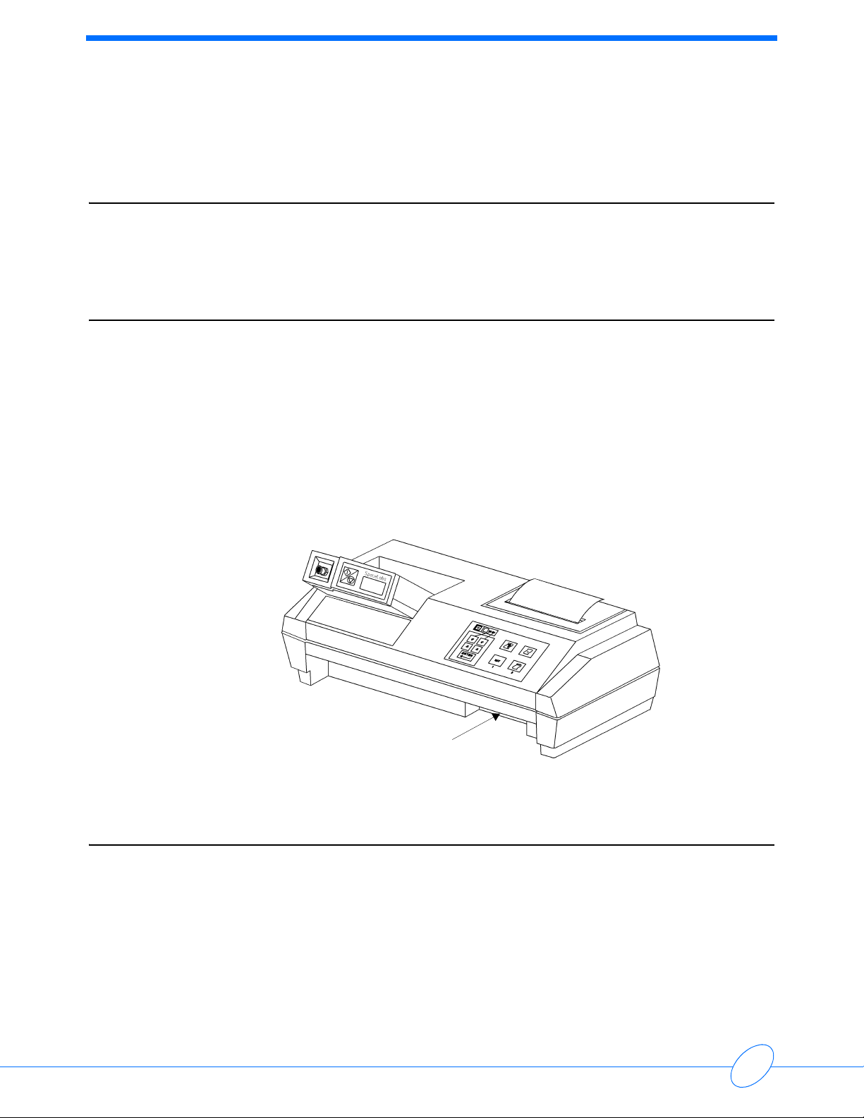
The 90239A Ambulatory Blood Pressure (ABP) Report Generator assembles raw blood pressure
data collected by the 90207 ABP monitor into tabular and/or graphical reports. This information
can be printed immediately or transferred to data cards for storage and for printing at a later time.
A battery backed-up real-time clock/calendar and memory store the configuration setups.
A card slot in the front of the Report Generator (refer to Figure 1-1) accepts the following:
• a program update card (for changing the program contained on an internal Flash ROM),
-OR-
• a data card (for storing patient data retrieved from the 90207 ABP Monitor).
Figure 1-1: 90239A ABP Report Generator
Specifications
Physical
Height: 3 inches (7.6 cm)
Width: 10 inches (25.4 cm)
Depth: 6 inches (15.2 cm)
Weight: 1 lb 6.2 oz (0.63 Kg)
Card Slot

Ambulatory Blood Pressure Report Generator/Printer
1-2
Power
120 Volts AC/9 VDC, 800mA adapter (P/N 334-0264-01)
240 Volts AC/9 VDC, 800mA adapter (P/N 119-0125-00)
Operating Environment
Temperature: +50° F to +104° F (+10° C to +40° C)
Relative Humidity: 0% to 95% non-condensing
Altitude: -500 to 10,000 feet (-200 to 3900 meters)
Vibration: 0.025-inch (0.635mm) displacement in all three axis from
10 to 60 Hz
Non-Operating Environment
Temperature: -29° F to +149° F (-34° C to +65° C)
Relative Humidity: 0% to 95% non-condensing
Altitude: -500 to 10,000 feet (-200 to 3900 meters)
Vibration: 0.025-inch (0.635mm) displacement in all three axis from
10 to 60 Hz
Radio Frequency Interference
Standards
VDE: 0871, Class B
FCC: Class B
Ambulatory Blood Pressure Report Generator/Printer
1-3
Introduction
Control Panel Keys
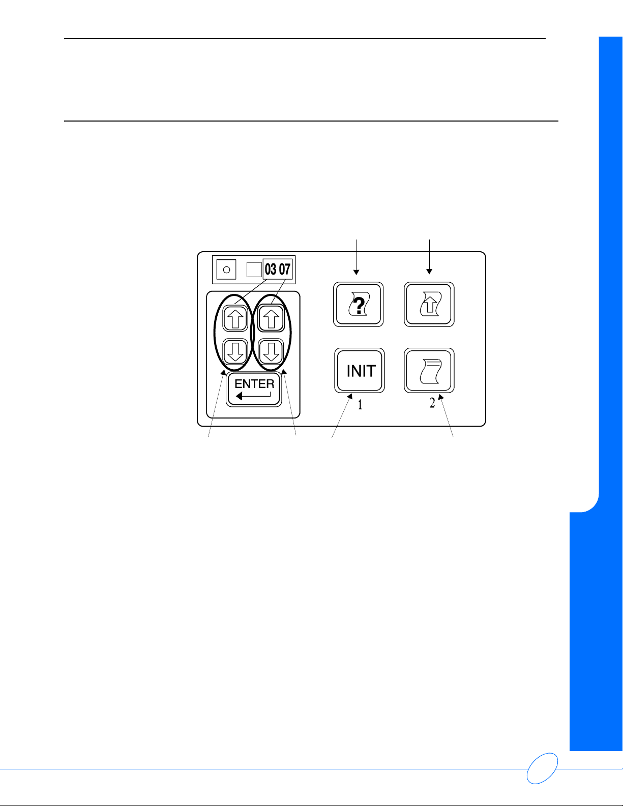
The user enters requests to the Report Generator by using two groups of keys located on the front
of the unit (refer to Figure 1-2). These keys are fully explained in the 90239A ABP Report
Generator Operations Manual (P/N 070-0399-xx).
• Use the group of four keys on the right to immediately execute a function.
• Use the group of five keys on the left to program the ABP Monitor.
Figure 1-2: Control panel keys
HELP (symbolized by a question mark on a sheet of paper)
INIT (pressing this key initializes the ABP Monitor)
PRINT (symbolized by a sheet of paper containing two lines of text)
PAPER ADVANCE (symbolized by a sheet of paper with an UP arrow)
The left pair of UP/DOWN arrows affect the two left-most digits on the ABP Monitor display
The right pair of UP/DOWN arrows affect the two right-most digits on the ABP Monitor display


Contents
2-1
Installation and Set-up
Overview . . . . . . . . . . . . . . . . . . . . . . . . . . . . . . . . . . . . . . . . . . . . . . . . . . . . . . . . . . . 1
Loading Paper . . . . . . . . . . . . . . . . . . . . . . . . . . . . . . . . . . . . . . . . . . . . . . . . . . . . . . . 1
Removing Paper . . . . . . . . . . . . . . . . . . . . . . . . . . . . . . . . . . . . . . . . . . . . . . . . . . . . . 1
Power ON Self Test . . . . . . . . . . . . . . . . . . . . . . . . . . . . . . . . . . . . . . . . . . . . . . . . . . . 2
Overview
The Report Generator is shipped from the factory with the required software and hardware already
installed. The unit requires only an ABP Monitor and electrical power to function.
Loading Paper
Caution
Use only Spacelabs Medical thermal paper (P/N 006-0210-02) in the printer; the print
mechanism may be permanently damaged if other brands of paper are used.
1Orient the paper roll so that it feeds from the bottom, and then fold the left side of the paper over
so that the right side forms a point.
2Remove the plastic cover over the cradle, and then feed the point through the slot in the bottom
of the paper roll cradle until it emerges in the print area (the paper must feed from the bottom
of the roll).
3Pull the paper through until the fold clears the print area. (A pair of tweezers may help you
perform this step.)
4Feed the paper up through the slot in the printer cover.
5Replace the plastic cover. This cover MUST be in place during printer operation.
Removing Paper
To remove paper from the Report Generator, pull the paper in the direction of normal paper
movement.
Caution
DO NOT pull the paper backward through the printer. Reversing the normal direction of
paper movement may permanently damage the paper-feed mechanism. Refer to the
90239A ABP Report Generator Operations Manual (P/N 070-0399-xx) for further
information and instructions.

Ambulatory Blood Pressure Report Generator/Printer
2-2
Power ON Self Test
Each time the Report Generator is powered ON, it tests its RAM and ROM areas. After a
successful self-test, the Report Generator prints a message similar to the following:
If an error message prints out, refer to Troubleshooting on page 4-1.
Spacelabs 90239A
ABP Report Generator
Vxx.xx.xx
Copyright (c)
2004
Spacelabs
90207 V xx.xx.xx
Date: 03-Jun-04
Time: 14:37

Contents
3-1
Theory of Operation
Input/Output. . . . . . . . . . . . . . . . . . . . . . . . . . . . . . . . . . . . . . . . . . . . . . . . . . . . . . . . . 1
Central Processing Unit (CPU) . . . . . . . . . . . . . . . . . . . . . . . . . . . . . . . . . . . . . . . . . . 3
Block Diagram . . . . . . . . . . . . . . . . . . . . . . . . . . . . . . . . . . . . . . . . . . . . . . . . . . . . . . . 4
Routine Maintenance. . . . . . . . . . . . . . . . . . . . . . . . . . . . . . . . . . . . . . . . . . . . . . . . . . 4
Input/Output
Report Generator
The Report Generator communicates with the ABP Monitor over an infrared (IR) serial port. Two
lines are used: one to transmit and one to receive. The port is activated by an internal magnet in
the bottom of the chute on the Report Generator. This port is capable of baud rates up to
9600 bps.
Control Panel Key Logic
The processor periodically and sequentially scans the control panel keys to determine if any are
being pressed. This is determined by whether a key is logic high (+5 V) or low (0 V) when the key
line is read.
Internal Thermal Printer
The CPU controls the thermal printer by sending information to a buffer that feeds data lines to the
hot dot drivers. The motor control comes directly from the processor and goes to a motor drive
circuit that is capable of providing the power required to drive the motor. Motor rotation and hot dot
head position signals from the printer are conditioned and sent on to the processor fur use in
controlling the printer. The signals from the printer are conditioned and sent on to the processor for
use in controlling the printer. The motor rotation signal is a crude sine wave that is turned into a
square wave for use by the processor for synchronization.
Power Input
Power is provided from a wall transformer that provides unregulated +9 volts DC at 800 mA into
the rear of the Report Generator. This unregulated +9 VDC input voltage is filtered, and part of it is
stepped up to +12 VDC. It is then sent to the internal circuitry through three regulated power
supplies:
• +5 V provides power to analog and digital circuitry.
• +5PV supplies power to high-current sources such as the printer.
• +12 V used to program the Flash ROM.

Ambulatory Blood Pressure Report Generator/Printer
3-2
RAM/ROM
Program execution is dictated by the software on the Flash ROM and the microprocessor ROM.
The RAM performs two functions:
• holds patient data and variables during operations
• holds graphic images and other information used during the creation and printing of a report
All functional modes are programmed by means of an internal 256-KB Flash ROM, which performs
the following functions:
• holds the software necessary for each operational mode
• holds 8 KB of internal microprocessor code
• contains the software for the 90207 ABP Monitor
• contains phrases in five languages
The software for the monitor can be downloaded from the Report Generator if the code in the
monitor’s RAM needs to be updated.
ROM Card/Data Card
Two types of cards can be inserted into the card slot on the front of the Report Generator:
• A SRAM data card that holds patient data retrieved from ABP monitors is used for storage or
for printing at a later time. This type of card can be write-protected to prevent accidental
erasure of data.
• A Program updated card is used to update the Report Generator program in the Flash ROM
and also the most current ABP Monitor code.
Real-Time Clock
The Real-Time Clock is used for the following functions:
• storing the current time and date used in resetting the ABP Monitor during initialization and for
the printed report
• storing settings used in initialization
The Real-Time Clock has a battery backup so that the time or program settings are not lost after
programming. The clock also stores calibration information for controlling the hot dot intensity
during printing.

Ambulatory Blood Pressure Report Generator/Printer
3-3
Theory of Operation
Central Processing Unit (CPU)
The CPU (comprised of a microprocessor used in conjunction with the ROM and RAM and the
addressing logic) performs the following functions:
• executes the software stored in the flash ROM memory or microprocessor ROM
• stores, retrieves, and processes data
• controls the thermal printer for printing ABP reports and user messages
• scans the front panel keys and takes action when a key is pressed
• communicates with the ABP Monitor by using the infrared serial port in the monitor chute,
communicates with the Real-Time Clock, and communicates with the serial port and the data
key parallel I/O ports
• downloads software from the ROM program card and programs it into the Flash ROM
• transfers data from the ABP Monitor to the optional data card
The processor initially executes its instructions from the ROM internal to the microprocessor. If the
self-tests are passed, code can then be executed out of the Flash ROM. The processor can write
to the I/O devices by means of latches and buffers tied to the processor’s bus and with the
microprocessor’s I/O ports. The processor interfaces with the following devices:
• memory (microprocessor internal ROM, Flash ROM, plug-in data card RAM or Program
update card ROM, and main board RAM)
•printer
• ABP Monitor (through the IR serial port)
• Real-Time Clock (located on the main board)

Ambulatory Blood Pressure Report Generator/Printer
3-4
Block Diagram
Figure 3-1: 90239A Report Generator
Routine Maintenance
Cleaning
The following steps should be performed on an as-needed basis:
• Wipe all external surfaces with a damp cloth. Ensure that no dust, lint, etc., obstructs the
infrared window in the bottom of the chute.
• Remove the printer cover and vacuum out accumulated dirt and paper fiber from the print
head area. Use tweezers to remove paper scraps.
9VDCFROM
120/240 VAC
WALL TRANSFORMER
POWER SUPPLY
SCRATCH
RAM
32 KB
FLASH ROM
256 KB
ROM or
SRAM
CARD
CONNECTOR
THERMAL
PRINTER
SERIAL I/O
RS-232 PORT
DATA KEY
I/O PORT
ADDRESS
AND
CONTROL
LOGIC
DATA CARD OR
PROGRAM
UPDATE CARD
TO 90219
BASE STATION
+5 VDC/
+5PV
+12 VDC
DATA KEY
(PROVIDED ONLY WITH
DATA CARD OPTION)
CPU
CONTROL PANEL
DATA
LINES
ADDRESS
LINES
REAL-TIME
CLOCK
IR
INTERFACE
90207
ABP MONITOR

Contents
4-1
Troubleshooting
Main Board/Printer Unit . . . . . . . . . . . . . . . . . . . . . . . . . . . . . . . . . . . . . . . . . . . . . . . . 1
Control Panel. . . . . . . . . . . . . . . . . . . . . . . . . . . . . . . . . . . . . . . . . . . . . . . . . . . . . . . . 1
Error Messages . . . . . . . . . . . . . . . . . . . . . . . . . . . . . . . . . . . . . . . . . . . . . . . . . . . . . . 2
Additional Error Messages . . . . . . . . . . . . . . . . . . . . . . . . . . . . . . . . . . . . . . . . . . . . . 5
Repair . . . . . . . . . . . . . . . . . . . . . . . . . . . . . . . . . . . . . . . . . . . . . . . . . . . . . . . . . . . . .6
Assembly/Disassembly Procedures . . . . . . . . . . . . . . . . . . . . . . . . . . . . . . . . . . . . . . 6
Replacing the Control Panel . . . . . . . . . . . . . . . . . . . . . . . . . . . . . . . . . . . . . . . . . . . . 7
Replacing the Printer Unit . . . . . . . . . . . . . . . . . . . . . . . . . . . . . . . . . . . . . . . . . . . . . . 7
Replacing the Main Board . . . . . . . . . . . . . . . . . . . . . . . . . . . . . . . . . . . . . . . . . . . . . . 8
Top Level Assembly . . . . . . . . . . . . . . . . . . . . . . . . . . . . . . . . . . . . . . . . . . . . . . . . . . 9
Main Board/Printer Unit
The Report Generator should print out header information (software version, the current date, etc.)
at each power-up to indicate a functioning main board and printer unit.
If the header information doesn’t print at power-up, replace the printer unit first, then the main
board.
Control Panel
If the Report Generator does not respond to certain control panel commands, check the continuity
for the keys by using an ohmmeter across the J2 plug pins. Pin 1 is indicated on the plug by the
small triangle molded into the plastic.
Control Panel Key Continuity Between
Left UP arrow Pins 1 and 2
Left DOWN arrow Pins 1 and 5
Right UP arrow Pins 2 and 4
Right DOWN arrow Pins 4 and 5
ENTER key Pins 1 and 7
HELP key Pins 2 and 3
INIT key Pins 5 and 6
LINEFEED key Pins 6 and 7
PRINT REPORT key Pins 7 and 8

Ambulatory Blood Pressure Report Generator/Printer
4-2
Error Messages
Error messages print whenever a fault condition occurs during operation of the Report Generator.
These messages take one of the following forms:
• Interface Fault “n”
• Hardware Interface Fault “n”
•Error“n”
“n” represents one of the error numbers in the following table:
Error
Number Explanation and Possible Causes Printed Message
2
Serial time-out (the 90207 ABP Monitor and the Report
Generator failed to interface).
Low batteries in 90207 ABP Monitor.
90207 monitor removed before data was fully read out.
None
3
The 90207 ABP Monitor failed to understand instructions from
the Report Generator.
Low batteries in 90207 ABP Monitor or bad LEDs in Report
Generator.
90207 ABP Monitor misaligned in chute.
None
4
The 90207 ABP Monitor failed to give any response.
Low batteries or bad LEDs in Report Generator.
90207 ABP Monitor misaligned in chute.
None
5
Maximum retries exceeded.
Defective 90207 ABP Monitor.
Defective infrared LEDs in Report Generator.
None
6
Bad 90207 ABP Monitor RAM.
Refer to the 90207/90217 Ambulatory Blood Pressure
Monitors Operations Manual (P/N 070-0137-xx) for
instructions.
Low batteries.
Monitor RAM fault.
7
The Report Generator does not detect the 90207 ABP
Monitor in the chute.
Try reinserting the monitor into the chute.
Bad lithium battery in 90207 ABP Monitor.
Infrared LEDs on main board may be misaligned.
Missing magnet on main board.
Bad main board.
None
8
Low battery or bad clock chip on main board.
Try resetting the clock.
Bad lithium battery on the main board.
Bad main board.
90239A Hardware
Fault 8.

Ambulatory Blood Pressure Report Generator/Printer
4-3
Troubleshooting
9
Aborted printing the report.
Bad control panel.
Bad main board.
Print report aborted.
10
Aborted printing the Help menu.
Bad control panel.
Bad main board.
Print help aborted.
11
Aborted printing the data card summary.
Bad control panel.
Bad main board.
Print card summary
aborted.
12
Power was removed while updating the Report Generator
software or the update card was pulled out prematurely.
Bad main board.
None
13 The 90207 ABP Monitor contains no data.
Bad 90207 ABP Monitor.
Monitor contains no
data.
14
Setup data checksum error.
Bad control panel.
Bad main board.
Setup data
checksum error.
Resetting all menu
item values to
factory defaults.
Following is the
current date and
time. Verify and
correct if necessary.
15
Invalid time received from clock.
Bad control panel.
Bad main board.
Invalid 90239A time
or date detected.
Please reset time
and date.
16
Switch on data card set to write-protect.
Bad data card.
Bad main board.
None
17
The data card is full.
Bad data card.
Bad main board.
None
18
The data card is not formatted. Refer to the 90239A
Ambulatory Blood Pressure Report Generator Operations
Manual (P/N 070-0399-xx) for formatting instructions.
Bad data card.
Bad main board.
None
19
The data card has suffered a failure while printing data.
Bad scan report on data card. Reformat the card.
Bad main board.
None
Error
Number Explanation and Possible Causes Printed Message

Ambulatory Blood Pressure Report Generator/Printer
4-4
20
Unknown or write-protected card.
Turn write protection OFF.
Bad data card.
Bad main board.
Card is
unrecognized or
write protected.
21
Bad password.
Try removing batteries from the 90207 ABP Monitor, then
replacing them. Then reinitialize the monitor if using the
90219 ABP PC Direct/Base Station. This erases any data
currently stored in the 90207 ABP Monitor.
Monitor has a
different password.
Cannot unlock
monitor.
22 No lithium battery.
Bad lithium battery in 90207 ABP Monitor.
Missing lithium
battery.
23 Lithium battery low.
Bad lithium battery in 90207 ABP Monitor.
Lithium battery
measures low.
Replace lithium
battery.
24
Paper is not feeding through the print unit. If the 90207 ABP
Monitor is placed in the chute, it starts beeping to indicate a
printer jam problem.
After the problem is resolved, press the line feed key to print
the error message.
Aborted due to
printer fault. Try
again.
25
The data card is not present in the card slot.
Bad data card.
Bad main board.
No data card
present.
26
Low data card battery.
Improperly installed data card battery, or bad battery.
Defective data card.
Bad main board.
The data card
battery is low.
Error
Number Explanation and Possible Causes Printed Message

Ambulatory Blood Pressure Report Generator/Printer
4-5
Troubleshooting
Additional Error Messages
The following error messages can also print. Because these errors are not identified in the normal
program flow, they do not have error numbers.
Error
Number Printed Message Possible Causes
None
Monitor software fault. Loading monitor software.
90207 V xx.xx.xx. Monitor software successfully
installed in monitor.
Possible problem with
90207 ABP Monitor.
Bad main board.
None
AA batteries measure low. Replace batteries if they are
alkaline. Verify they have been fully charged if they are
NiCads.
Bad batteries in 90207
ABP Monitor.
90207 ABP Monitor
erroneously reading
battery charge as low.
None Software on update card is incompatible with system
software in 90239A. Update not performed.
Bad update card.
Bad main board.
None Data checksum error. Bad control panel.
Bad main board.
None Update card failed verification test. Update not
performed.
Perform software update
with another update card.
Bad main board.

Ambulatory Blood Pressure Report Generator/Printer
4-6
Repair
Refer to the board layout diagram below for component locations.
Assembly/Disassembly Procedures
Use a cross-tip (Phillips) screwdriver to complete most assembly/disassembly procedures.
Externally, four Phillips screws connect the upper and lower halves of the Report Generator.
• The upper half contains the front control panel and the thermal printer.
• The lower half contains the main board and the infrared LEDs that interface with the 90207
ABP Monitor.
• Internally, three cables also connect the upper and lower halves:
• One cable connects the control panel to the main board.
• Two cables connect the thermal printer unit to the main board.
To disassemble the Report Generator:
1Remove the four Phillips screws located on the bottom of the unit.
2Separate the unit into upper and lower halves (they will still be connected together by the
cables).
Other manuals for Spacelabs Medical 90239A
1
Table of contents
Other OSI Systems Medical Equipment manuals


Popular Medical Equipment manuals by other brands


Getinge
Getinge Arjohuntleigh Nimbus 3 Professional Instructions for use

Mettler Electronics
Mettler Electronics Sonicator 730 Maintenance manual

Pressalit Care
Pressalit Care R1100 Mounting instruction

Denas MS
Denas MS DENAS-T operating manual

bort medical
bort medical ActiveColor quick guide

AccuVein
AccuVein AV400 user manual


