OSI Systems Spacelabs Ultraview 1700 User manual

Universal Clinical Workstation
(UCW ) and
Ultraview 1700 Monitors
90385, 90387
Service Manual
070-0470-02 Rev. E
®
®

© 2004 Spacelabs Medical, Inc.
All rights reserved. Contents of this publication may not be reproduced in any form without the written permission of Spacelabs
Medical. Products of Spacelabs Medical are covered by U.S. and foreign patents and/or pending patents. Printed in U.S.A.
Specifications and price change privileges are reserved.
Spacelabs Medical considers itself responsible for the effects on safety, reliability and performance of the equipment only if:
• assembly operations, re-adjustments, modifications or repairs are carried out by persons authorized by Spacelabs
Medical, and
• the electrical installation of the relevant room complies with the requirements of the standard in force, and
• the equipment is used in accordance with the operations manual.
Spacelabs Medical will make available, on request, such circuit diagrams, component part lists, descriptions, calibration instructions
or other information which will assist appropriately qualified technical personnel to repair those parts of the equipment which are
classified by Spacelabs Medical as field repairable.
Spacelabs Medical is committed to providing comprehensive customer support beginning with your initial inquiry through purchase,
training, and service for the life of your Spacelabs Medical equipment.
CORPORATE OFFICES
U.S.A.
Spacelabs Medical, Inc.
5150 220th Ave SE
Issaquah, WA 98029
Telephone: 425-657-7200
Telephone: 800-522-7025
Fax: 425-657-7212
Authorized EC Representative
UNITED KINGDOM
Spacelabs Medical Ltd.
Basepoint Business Centre
Metcalf Way, Crawley
West Sussex RH11 7XX
Telephone: 44 (0) 845 6017224
Fax: 44 (0) 845 6017225
BirthNet, Data Shuttle, Flexport, Intesys Clinical Suite, Maternal Obstetrical Monitor, MOM, Mermaid, Multiview, PCIS, PCMS,
PrintMaster, Quicknet, Sensorwatch, TRU-CAP, TRU-CUFF, TRU-LINK, UCW, Ultralite, Ultraview, Ultraview Clinical Messenger,
Ultraview SL, Uni-Pouch, Universal Flexport, Varitrend and WinDNA are trademarks of Spacelabs Medical, Inc.
Other brands and product names are trademarks of their respective owners.
CAUTION:
US Federal law restricts the devices documented herein to sale by, or on the order
of, a physician.
Rx
Only

i
Chapter Page
Table of Contents
Introduction
Overview . . . . . . . . . . . . . . . . . . . . . . . . . . . . . . . . . . . . . . . . . . . . . . . . . . . . . . . . . . . . . . . .1-1
Accessories . . . . . . . . . . . . . . . . . . . . . . . . . . . . . . . . . . . . . . . . . . . . . . . . . . . . . . . . . . . . . .1-4
Monitor Options . . . . . . . . . . . . . . . . . . . . . . . . . . . . . . . . . . . . . . . . . . . . . . . . . . . . . . . 1-4
Equipment Illustrations — Rear. . . . . . . . . . . . . . . . . . . . . . . . . . . . . . . . . . . . . . . . . . . . . . . 1-6
UCW (90385) . . . . . . . . . . . . . . . . . . . . . . . . . . . . . . . . . . . . . . . . . . . . . . . . . . . . . . . . . 1-6
Ultraview 1700 (90387) . . . . . . . . . . . . . . . . . . . . . . . . . . . . . . . . . . . . . . . . . . . . . . . . . 1-7
Setup
Specifications . . . . . . . . . . . . . . . . . . . . . . . . . . . . . . . . . . . . . . . . . . . . . . . . . . . . . . . . . . . .2-1
90385 . . . . . . . . . . . . . . . . . . . . . . . . . . . . . . . . . . . . . . . . . . . . . . . . . . . . . . . . . . . . . . 2-1
90387 . . . . . . . . . . . . . . . . . . . . . . . . . . . . . . . . . . . . . . . . . . . . . . . . . . . . . . . . . . . . . . 2-2
Inspection . . . . . . . . . . . . . . . . . . . . . . . . . . . . . . . . . . . . . . . . . . . . . . . . . . . . . . . . . . . . . . . 2-2
Pre-Installation Testing . . . . . . . . . . . . . . . . . . . . . . . . . . . . . . . . . . . . . . . . . . . . . . . . . . . . . 2-3
Mounting . . . . . . . . . . . . . . . . . . . . . . . . . . . . . . . . . . . . . . . . . . . . . . . . . . . . . . . . . . . . . . . .2-3
Base Tension Adjustment (90385). . . . . . . . . . . . . . . . . . . . . . . . . . . . . . . . . . . . . . . . . 2-3
Wall Mounting . . . . . . . . . . . . . . . . . . . . . . . . . . . . . . . . . . . . . . . . . . . . . . . . . . . . . . . .2-4
Pedestal Mounting (90385) . . . . . . . . . . . . . . . . . . . . . . . . . . . . . . . . . . . . . . . . . . . . . .2-5
Console Mounting (90387) . . . . . . . . . . . . . . . . . . . . . . . . . . . . . . . . . . . . . . . . . . . . . . .2-6
Installation . . . . . . . . . . . . . . . . . . . . . . . . . . . . . . . . . . . . . . . . . . . . . . . . . . . . . . . . . . . . . . .2-8
Cables (90385). . . . . . . . . . . . . . . . . . . . . . . . . . . . . . . . . . . . . . . . . . . . . . . . . . . . . . . .2-8
Cables (90387). . . . . . . . . . . . . . . . . . . . . . . . . . . . . . . . . . . . . . . . . . . . . . . . . . . . . . . .2-9
Ethernet LAN Cables . . . . . . . . . . . . . . . . . . . . . . . . . . . . . . . . . . . . . . . . . . . . . . . . . . 2-11
SDLC Bus Connections . . . . . . . . . . . . . . . . . . . . . . . . . . . . . . . . . . . . . . . . . . . . . . . . 2-12
Maximum Cable Lengths . . . . . . . . . . . . . . . . . . . . . . . . . . . . . . . . . . . . . . . . . . . . . . .2-12
Network Configuration. . . . . . . . . . . . . . . . . . . . . . . . . . . . . . . . . . . . . . . . . . . . . . . . . . . . . 2-13
Ethernet LAN Installation . . . . . . . . . . . . . . . . . . . . . . . . . . . . . . . . . . . . . . . . . . . . . . . 2-14
System Configuration . . . . . . . . . . . . . . . . . . . . . . . . . . . . . . . . . . . . . . . . . . . . . . . . . . . . . 2-14
Keyboard Menu . . . . . . . . . . . . . . . . . . . . . . . . . . . . . . . . . . . . . . . . . . . . . . . . . . . . . . 2-19
Biomed Setup Menu . . . . . . . . . . . . . . . . . . . . . . . . . . . . . . . . . . . . . . . . . . . . . . . . . . . . . . 2-20
Network Setup Menu . . . . . . . . . . . . . . . . . . . . . . . . . . . . . . . . . . . . . . . . . . . . . . . . . . 2-20
Preselected Recordings Menu . . . . . . . . . . . . . . . . . . . . . . . . . . . . . . . . . . . . . . . . . . . 2-22
Recorder Setup Menu . . . . . . . . . . . . . . . . . . . . . . . . . . . . . . . . . . . . . . . . . . . . . . . . . 2-23
Serial Ports Menu. . . . . . . . . . . . . . . . . . . . . . . . . . . . . . . . . . . . . . . . . . . . . . . . . . . . . 2-24
Alarm Setup Menu . . . . . . . . . . . . . . . . . . . . . . . . . . . . . . . . . . . . . . . . . . . . . . . . . . . . 2-25
User Access Menu . . . . . . . . . . . . . . . . . . . . . . . . . . . . . . . . . . . . . . . . . . . . . . . . . . . . 2-27
UNITS OF MEASURE MENU Key. . . . . . . . . . . . . . . . . . . . . . . . . . . . . . . . . . . . . . . . 2-27
Tone Configuration Menu. . . . . . . . . . . . . . . . . . . . . . . . . . . . . . . . . . . . . . . . . . . . . . . 2-27
Service Functions Menu. . . . . . . . . . . . . . . . . . . . . . . . . . . . . . . . . . . . . . . . . . . . . . . . 2-28
Theory
UCW (90385) . . . . . . . . . . . . . . . . . . . . . . . . . . . . . . . . . . . . . . . . . . . . . . . . . . . . . . . . . . . . 3-1
Monitor Power Supply . . . . . . . . . . . . . . . . . . . . . . . . . . . . . . . . . . . . . . . . . . . . . . . . . . 3-2
CRT Display . . . . . . . . . . . . . . . . . . . . . . . . . . . . . . . . . . . . . . . . . . . . . . . . . . . . . . . . . . 3-2
Touchscreen Assembly . . . . . . . . . . . . . . . . . . . . . . . . . . . . . . . . . . . . . . . . . . . . . . . . . 3-2
Ultraview 1700 (90387) . . . . . . . . . . . . . . . . . . . . . . . . . . . . . . . . . . . . . . . . . . . . . . . . . . . . .3-3
Monitor Power Supply . . . . . . . . . . . . . . . . . . . . . . . . . . . . . . . . . . . . . . . . . . . . . . . . . . 3-4
Display . . . . . . . . . . . . . . . . . . . . . . . . . . . . . . . . . . . . . . . . . . . . . . . . . . . . . . . . . . . . . . 3-4
Touchscreen Assembly . . . . . . . . . . . . . . . . . . . . . . . . . . . . . . . . . . . . . . . . . . . . . . . . . 3-4

UCW and Ultraview 1700 Monitors
ii
CPU PCBA . . . . . . . . . . . . . . . . . . . . . . . . . . . . . . . . . . . . . . . . . . . . . . . . . . . . . . . . . . . . . . 3-5
Main CPU . . . . . . . . . . . . . . . . . . . . . . . . . . . . . . . . . . . . . . . . . . . . . . . . . . . . . . . . . . . 3-6
Memory . . . . . . . . . . . . . . . . . . . . . . . . . . . . . . . . . . . . . . . . . . . . . . . . . . . . . . . . . . . . . 3-6
MPC860-PCI Bridge . . . . . . . . . . . . . . . . . . . . . . . . . . . . . . . . . . . . . . . . . . . . . . . . . . . 3-6
Video . . . . . . . . . . . . . . . . . . . . . . . . . . . . . . . . . . . . . . . . . . . . . . . . . . . . . . . . . . . . . . . 3-7
Ethernet. . . . . . . . . . . . . . . . . . . . . . . . . . . . . . . . . . . . . . . . . . . . . . . . . . . . . . . . . . . . . 3-7
ISA Bridge . . . . . . . . . . . . . . . . . . . . . . . . . . . . . . . . . . . . . . . . . . . . . . . . . . . . . . . . . . . 3-7
Audio . . . . . . . . . . . . . . . . . . . . . . . . . . . . . . . . . . . . . . . . . . . . . . . . . . . . . . . . . . . . . . . 3-7
Non-Volatile RAM/Real-Time Clock . . . . . . . . . . . . . . . . . . . . . . . . . . . . . . . . . . . . . . . 3-7
Keyboard/Mouse Interface . . . . . . . . . . . . . . . . . . . . . . . . . . . . . . . . . . . . . . . . . . . . . . 3-8
EPP Port . . . . . . . . . . . . . . . . . . . . . . . . . . . . . . . . . . . . . . . . . . . . . . . . . . . . . . . . . . . . 3-8
ISA I/O Buffers . . . . . . . . . . . . . . . . . . . . . . . . . . . . . . . . . . . . . . . . . . . . . . . . . . . . . . . 3-8
SDLC Interface . . . . . . . . . . . . . . . . . . . . . . . . . . . . . . . . . . . . . . . . . . . . . . . . . . . . . . . 3-8
Nurse Alarm Output. . . . . . . . . . . . . . . . . . . . . . . . . . . . . . . . . . . . . . . . . . . . . . . . . . . . 3-8
Clock Distribution . . . . . . . . . . . . . . . . . . . . . . . . . . . . . . . . . . . . . . . . . . . . . . . . . . . . . 3-8
Hardware Reset . . . . . . . . . . . . . . . . . . . . . . . . . . . . . . . . . . . . . . . . . . . . . . . . . . . . . . 3-9
Software Reset . . . . . . . . . . . . . . . . . . . . . . . . . . . . . . . . . . . . . . . . . . . . . . . . . . . . . . . 3-9
Power Failure Operation . . . . . . . . . . . . . . . . . . . . . . . . . . . . . . . . . . . . . . . . . . . . . . . 3-10
Hard Reset Configuration Word . . . . . . . . . . . . . . . . . . . . . . . . . . . . . . . . . . . . . . . . . 3-10
Interrupts . . . . . . . . . . . . . . . . . . . . . . . . . . . . . . . . . . . . . . . . . . . . . . . . . . . . . . . . . . . 3-10
Regulator for -5 Volts . . . . . . . . . . . . . . . . . . . . . . . . . . . . . . . . . . . . . . . . . . . . . . . . . 3-11
Regulator for -3.3 Volts . . . . . . . . . . . . . . . . . . . . . . . . . . . . . . . . . . . . . . . . . . . . . . . . 3-11
Power Supply Connector. . . . . . . . . . . . . . . . . . . . . . . . . . . . . . . . . . . . . . . . . . . . . . . 3-11
EMI Reduction. . . . . . . . . . . . . . . . . . . . . . . . . . . . . . . . . . . . . . . . . . . . . . . . . . . . . . . 3-12
Boot Sequence Overview . . . . . . . . . . . . . . . . . . . . . . . . . . . . . . . . . . . . . . . . . . . . . . 3-12
Normal Operation Overview . . . . . . . . . . . . . . . . . . . . . . . . . . . . . . . . . . . . . . . . . . . . 3-12
CPU External Connectors . . . . . . . . . . . . . . . . . . . . . . . . . . . . . . . . . . . . . . . . . . . . . . 3-14
I/O PCBA . . . . . . . . . . . . . . . . . . . . . . . . . . . . . . . . . . . . . . . . . . . . . . . . . . . . . . . . . . . . . . 3-15
IR Touchscreen Connector (90385 Only) . . . . . . . . . . . . . . . . . . . . . . . . . . . . . . . . . . 3-15
Video RGB Connector (90385 Only) . . . . . . . . . . . . . . . . . . . . . . . . . . . . . . . . . . . . . . 3-16
I/O External Connectors . . . . . . . . . . . . . . . . . . . . . . . . . . . . . . . . . . . . . . . . . . . . . . . 3-17
Interconnect PCBA . . . . . . . . . . . . . . . . . . . . . . . . . . . . . . . . . . . . . . . . . . . . . . . . . . . . . . . 3-18
Maintenance
Overview. . . . . . . . . . . . . . . . . . . . . . . . . . . . . . . . . . . . . . . . . . . . . . . . . . . . . . . . . . . . . . . . 4-1
Cleaning/Disinfecting . . . . . . . . . . . . . . . . . . . . . . . . . . . . . . . . . . . . . . . . . . . . . . . . . . . . . . 4-1
Filter and Fan (90385 Only) . . . . . . . . . . . . . . . . . . . . . . . . . . . . . . . . . . . . . . . . . . . . . 4-2
Touchscreen (90385 Only) . . . . . . . . . . . . . . . . . . . . . . . . . . . . . . . . . . . . . . . . . . . . . . 4-2
Preventive Maintenance (PM) Procedures. . . . . . . . . . . . . . . . . . . . . . . . . . . . . . . . . . . . . . 4-3
Test Equipment Required . . . . . . . . . . . . . . . . . . . . . . . . . . . . . . . . . . . . . . . . . . . . . . . 4-3
Mechanical Safety Check . . . . . . . . . . . . . . . . . . . . . . . . . . . . . . . . . . . . . . . . . . . . . . . 4-3
Electrical Safety Testing . . . . . . . . . . . . . . . . . . . . . . . . . . . . . . . . . . . . . . . . . . . . . . . . . . . . 4-3
Definitions. . . . . . . . . . . . . . . . . . . . . . . . . . . . . . . . . . . . . . . . . . . . . . . . . . . . . . . . . . . . . . . 4-3
Ground Resistance . . . . . . . . . . . . . . . . . . . . . . . . . . . . . . . . . . . . . . . . . . . . . . . . . . . . 4-4
Chassis Leakage Current Tests . . . . . . . . . . . . . . . . . . . . . . . . . . . . . . . . . . . . . . . . . . 4-5
Patient Lead Leakage Current Tests (Patient Modules) . . . . . . . . . . . . . . . . . . . . . . . . 4-5
Monitor Functional Tests . . . . . . . . . . . . . . . . . . . . . . . . . . . . . . . . . . . . . . . . . . . . . . . . 4-5
Error Log . . . . . . . . . . . . . . . . . . . . . . . . . . . . . . . . . . . . . . . . . . . . . . . . . . . . . . . . . . . . 4-7
Display Adjustments (90385) . . . . . . . . . . . . . . . . . . . . . . . . . . . . . . . . . . . . . . . . . . . . 4-7
Display Adjustments (90387) . . . . . . . . . . . . . . . . . . . . . . . . . . . . . . . . . . . . . . . . . . . 4-10
Disassembly Procedures (90385) . . . . . . . . . . . . . . . . . . . . . . . . . . . . . . . . . . . . . . . . . . . 4-11
Tools Required . . . . . . . . . . . . . . . . . . . . . . . . . . . . . . . . . . . . . . . . . . . . . . . . . . . . . . 4-11
Top Cover Removal . . . . . . . . . . . . . . . . . . . . . . . . . . . . . . . . . . . . . . . . . . . . . . . . . . 4-11
PCBA Drawer Removal/Replacement. . . . . . . . . . . . . . . . . . . . . . . . . . . . . . . . . . . . . 4-14
NVRAM Replacement . . . . . . . . . . . . . . . . . . . . . . . . . . . . . . . . . . . . . . . . . . . . . . . . . 4-15
CPU PCBA Replacement . . . . . . . . . . . . . . . . . . . . . . . . . . . . . . . . . . . . . . . . . . . . . . 4-15

Table of Contents
iii
Interconnect PCBA Replacement . . . . . . . . . . . . . . . . . . . . . . . . . . . . . . . . . . . . . . . .4-16
I/O PCBA Removal/Replacement . . . . . . . . . . . . . . . . . . . . . . . . . . . . . . . . . . . . . . . . 4-17
Touchscreen Removal/Reassembly . . . . . . . . . . . . . . . . . . . . . . . . . . . . . . . . . . . . . . 4-18
Exhaust Fan Replacement. . . . . . . . . . . . . . . . . . . . . . . . . . . . . . . . . . . . . . . . . . . . . . 4-19
AC Switch Replacement (90385) . . . . . . . . . . . . . . . . . . . . . . . . . . . . . . . . . . . . . . . . . 4-20
Disassembly Procedures (90387) . . . . . . . . . . . . . . . . . . . . . . . . . . . . . . . . . . . . . . . . . . . . 4-21
Tools Required. . . . . . . . . . . . . . . . . . . . . . . . . . . . . . . . . . . . . . . . . . . . . . . . . . . . . . . 4-21
Backup Battery Replacement . . . . . . . . . . . . . . . . . . . . . . . . . . . . . . . . . . . . . . . . . . . 4-21
Divider Removal. . . . . . . . . . . . . . . . . . . . . . . . . . . . . . . . . . . . . . . . . . . . . . . . . . . . . . 4-21
Enclosure Removal . . . . . . . . . . . . . . . . . . . . . . . . . . . . . . . . . . . . . . . . . . . . . . . . . . . 4-22
Bezel Removal . . . . . . . . . . . . . . . . . . . . . . . . . . . . . . . . . . . . . . . . . . . . . . . . . . . . . . . 4-22
Rear Panel Removal . . . . . . . . . . . . . . . . . . . . . . . . . . . . . . . . . . . . . . . . . . . . . . . . . . 4-22
Backplane PCBA Removal . . . . . . . . . . . . . . . . . . . . . . . . . . . . . . . . . . . . . . . . . . . . . 4-22
PCBA Drawer Removal/Replacement . . . . . . . . . . . . . . . . . . . . . . . . . . . . . . . . . . . . . 4-23
NVRAM Replacement . . . . . . . . . . . . . . . . . . . . . . . . . . . . . . . . . . . . . . . . . . . . . . . . . 4-24
CPU PCBA Replacement. . . . . . . . . . . . . . . . . . . . . . . . . . . . . . . . . . . . . . . . . . . . . . . 4-24
Interconnect PCBA Replacement . . . . . . . . . . . . . . . . . . . . . . . . . . . . . . . . . . . . . . . .4-25
I/O PCBA Removal/Replacement . . . . . . . . . . . . . . . . . . . . . . . . . . . . . . . . . . . . . . . . 4-26
Power Interconnect PCBA Removal . . . . . . . . . . . . . . . . . . . . . . . . . . . . . . . . . . . . . . 4-26
Troubleshooting
Overview . . . . . . . . . . . . . . . . . . . . . . . . . . . . . . . . . . . . . . . . . . . . . . . . . . . . . . . . . . . . . . . .5-1
Suggested Tools and Parts . . . . . . . . . . . . . . . . . . . . . . . . . . . . . . . . . . . . . . . . . . . . . . . . . .5-1
Symptoms . . . . . . . . . . . . . . . . . . . . . . . . . . . . . . . . . . . . . . . . . . . . . . . . . . . . . . . . . . . . . . .5-2
Monitor Has No Display . . . . . . . . . . . . . . . . . . . . . . . . . . . . . . . . . . . . . . . . . . . . . . . . . 5-2
Monitor Operates but Fails System Functions . . . . . . . . . . . . . . . . . . . . . . . . . . . . . . . . 5-3
Monitor Diagnostics. . . . . . . . . . . . . . . . . . . . . . . . . . . . . . . . . . . . . . . . . . . . . . . . . . . . . . . . 5-4
Power-ON Diagnostics. . . . . . . . . . . . . . . . . . . . . . . . . . . . . . . . . . . . . . . . . . . . . . . . . . 5-4
Extended Diagnostics . . . . . . . . . . . . . . . . . . . . . . . . . . . . . . . . . . . . . . . . . . . . . . . . . . 5-5
Diagnostic LED . . . . . . . . . . . . . . . . . . . . . . . . . . . . . . . . . . . . . . . . . . . . . . . . . . . . . . .5-5
Monitor Fails Power-ON Diagnostics . . . . . . . . . . . . . . . . . . . . . . . . . . . . . . . . . . . . . . . 5-5
System Startup . . . . . . . . . . . . . . . . . . . . . . . . . . . . . . . . . . . . . . . . . . . . . . . . . . . . . . . . . . .5-9
Boot Menu . . . . . . . . . . . . . . . . . . . . . . . . . . . . . . . . . . . . . . . . . . . . . . . . . . . . . . . . . . . . . . 5-10
Diagnostic Menus . . . . . . . . . . . . . . . . . . . . . . . . . . . . . . . . . . . . . . . . . . . . . . . . . . . . . . . .5-12
Parts
Field-Replaceable Parts . . . . . . . . . . . . . . . . . . . . . . . . . . . . . . . . . . . . . . . . . . . . . . . . . . . .6-1
9-pin and 26-pin SDLC. . . . . . . . . . . . . . . . . . . . . . . . . . . . . . . . . . . . . . . . . . . . . . . . . .6-1
Miscellaneous Cables . . . . . . . . . . . . . . . . . . . . . . . . . . . . . . . . . . . . . . . . . . . . . . . . . .6-1
PCBAs . . . . . . . . . . . . . . . . . . . . . . . . . . . . . . . . . . . . . . . . . . . . . . . . . . . . . . . . . . . . . .6-2
Miscellaneous Parts . . . . . . . . . . . . . . . . . . . . . . . . . . . . . . . . . . . . . . . . . . . . . . . . . . . . 6-2
Ethernet 10BaseT . . . . . . . . . . . . . . . . . . . . . . . . . . . . . . . . . . . . . . . . . . . . . . . . . . . . . 6-4
Assembly Drawings. . . . . . . . . . . . . . . . . . . . . . . . . . . . . . . . . . . . . . . . . . . . . . . . . . . . . . . .6-4
Appendix A — Electromagnetic Compatibility
Electromagnetic Emissions . . . . . . . . . . . . . . . . . . . . . . . . . . . . . . . . . . . . . . . . . . . . . . . . . .A-1
Electromagnetic Immunity . . . . . . . . . . . . . . . . . . . . . . . . . . . . . . . . . . . . . . . . . . . . . . . . . . .A-2
Frequency Separation Distances . . . . . . . . . . . . . . . . . . . . . . . . . . . . . . . . . . . . . . . . . . . . .A-3
Interference . . . . . . . . . . . . . . . . . . . . . . . . . . . . . . . . . . . . . . . . . . . . . . . . . . . . . . . . . .A-4
Mitigation . . . . . . . . . . . . . . . . . . . . . . . . . . . . . . . . . . . . . . . . . . . . . . . . . . . . . . . . . . . .A-4
Appendix B — Symbols


1-1
Contents
Introduction
Overview
Spacelabs Medical’s products are designed and manufactured under good manufacturing practices
and in compliance with all applicable regulatory requirements. To ensure proper operation in
accordance with these guidelines, this product must be maintained by trained technicians using
Spacelabs Medical authorized replacement parts.
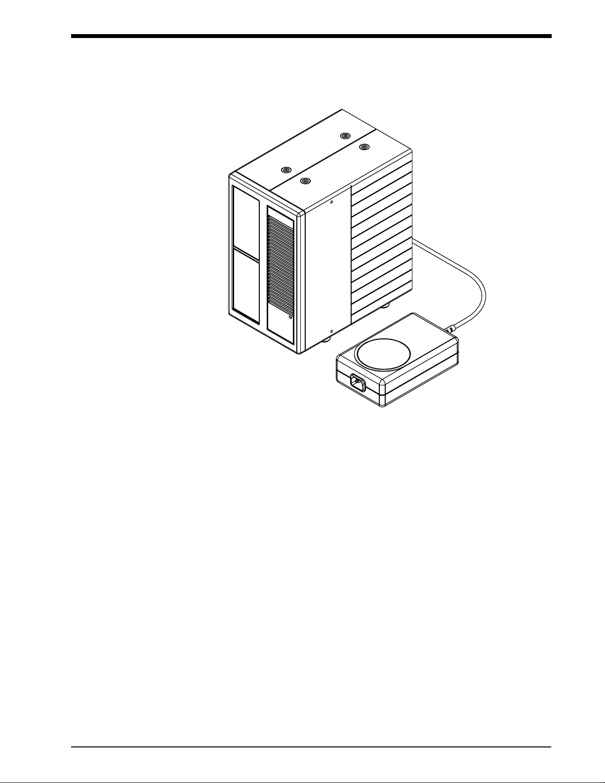
This manual applies to the 90385 Universal Clinical Workstation (UCW®) and the 90387 Ultraview®
1700 monitors. The 90385 UCW monitor is a fully Ultraview-compatible bedside or central monitor. It
features a 15-inch color display and an infrared touchscreen.
The 90387 Ultraview 1700 monitor combines the module-mounting capability of the 90491 module
housing, with the processing and display capabilities of the 90385 UCW. The right side of the
chassis is used to house the CPU and I/O PCBAs, while the left side provides two slots for module
plug-in. The Ultraview 1700 is capable of driving an external speaker (either amplified or
unamplified) or may stand alone, using the internal speaker. The result is a product that provides the
same Ultraview Care Network™capabilities as the UCW, but adds plug-in support for two modules
in a single, compact unit, with a separate display. The Ultraview 1700 is primarily intended to
function as a compact, two-module bedside or central monitor.
!• This service manual is intended for use with 90385 monitors, serial numbers
385-3xxx and higher, and 90387 monitors, serial numbers 387-1xxx and higher.
Overview. . . . . . . . . . . . . . . . . . . . . . . . . . . . . . . . . . . . . . . . . . . . . . . . . . . . . . . . . . . . . . . . . . . . . . 1
Accessories . . . . . . . . . . . . . . . . . . . . . . . . . . . . . . . . . . . . . . . . . . . . . . . . . . . . . . . . . . . . . . . . . . . 4
Equipment Illustrations — Rear . . . . . . . . . . . . . . . . . . . . . . . . . . . . . . . . . . . . . . . . . . . . . . . . . . . . 6

Introduction
1-3
Figure 1-3: Ultraview 1700 with external power supply

UCW and Ultraview 1700 Monitors — Service Manual
1-4
Accessories
Monitor Options
* For central configurations (Option A): If Options N or O are selected, then option P must
be selected.
** Option X is only valid for the 90385 monitor.
*** 90360-01 and 90360-03 are required and must be purchased separately when used with
model 90387.
**** 90360-01 is required and must be purchased when used with model 90385.
† Option -07 is only valid for the 90387 monitor; options N, O, R, S, and T are not valid with this option.
Table 1: UCW and Ultraview 1700 Options
Option Definition
-A Central/Bedside *
-B Bedside
-F Four Waveforms
-G Five Waveforms
-H Six Waveforms
-I Seven Waveforms
-J Eight Waveforms
-K Twelve Waveform
-L Sixteen Waveforms
-M Graphic and Tabular Trends
-N Vital Sign Calculations *†
-O Drug Dose Calculations *†
-P Interactive Network
-Q Data Shuttle
-R Patient Data Logger †
-S Dynamic Network Access (DNA) †
-T IR Remote Control *** **** †
-V Full View
-W Full Bed Review
-X 220–240 Volt Operation **
-01 English
-02 German
-03 French
-04 Italian
-05 Spanish
-06 Swedish
-07 Polish †
-09 Dutch

Introduction
1-5
Example:
A 90385-XFQ (where “X” represents the language designator) is an UCW equipped with:
• Q = Data Shuttle option
• F = Four waveform zones
Accessory devices supported by the UCW/1700 are as follows:
Modules — Supports all existing Ultraview modules except 90425, 90428, 90432, and 90410. Use
of modules in conjunction with the UCW requires a module housing(s) and DC power supply(s);
whereas, the Ultraview 1700 provides plug-in support for either two single-height modules or one
double-height module. Additional modules are supported by means of external module housings.
Flexport®system interfaces — Supports the use of all existing Spacelabs Medical Flexport
interfaces. Refer to Setup on page 2-1 for installation requirements.
Repeater Displays — Up to two repeater displays may be connected. The repeater displays serve
only to duplicate the information shown on the Ultraview monitor and does not accept user input.
Repeater displays may be located up to 100 feet from the Ultraview monitor.
Touchscreen — The Ultraview 1700 supports the ELO Touch brand touchscreens. The UCW uses
an integral infrared touchscreen.
Mouse — Supports the use of a PS/2-style mouse.
Keyboard — Supports the use of a PS/2-style keyboard.
Nurse Alert — Supports the use of a Spacelabs Medical nurse alert device. This device provides an
external indication that one of the parameters being monitored is in an alarm condition.
UCW and Ultraview 1700 Monitors — Service Manual
1-6
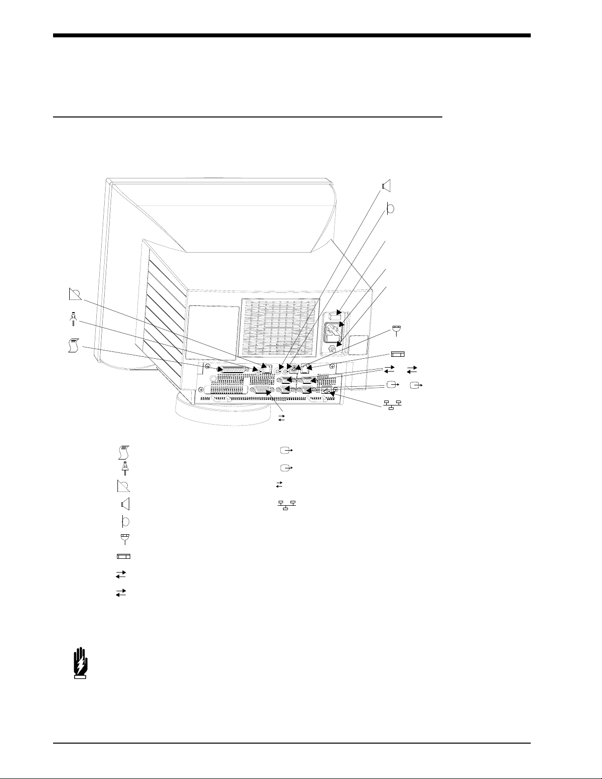
Equipment Illustrations — Rear
UCW (90385)
Figure 1-4: Rear view (90385)
WARNING:
• For safety, the power cord retainer hardware must always be used.
unavailable
unavailable
nurse alert
speaker
unavailable
mouse port
keyboard
serial out 1
serial out 2
video out 1
video out 2
SDLC
network connection
ON/OFF switch
power cord receptacle
ground lug
12
SDLC
12
1
2
SDLC
Introduction
1-7
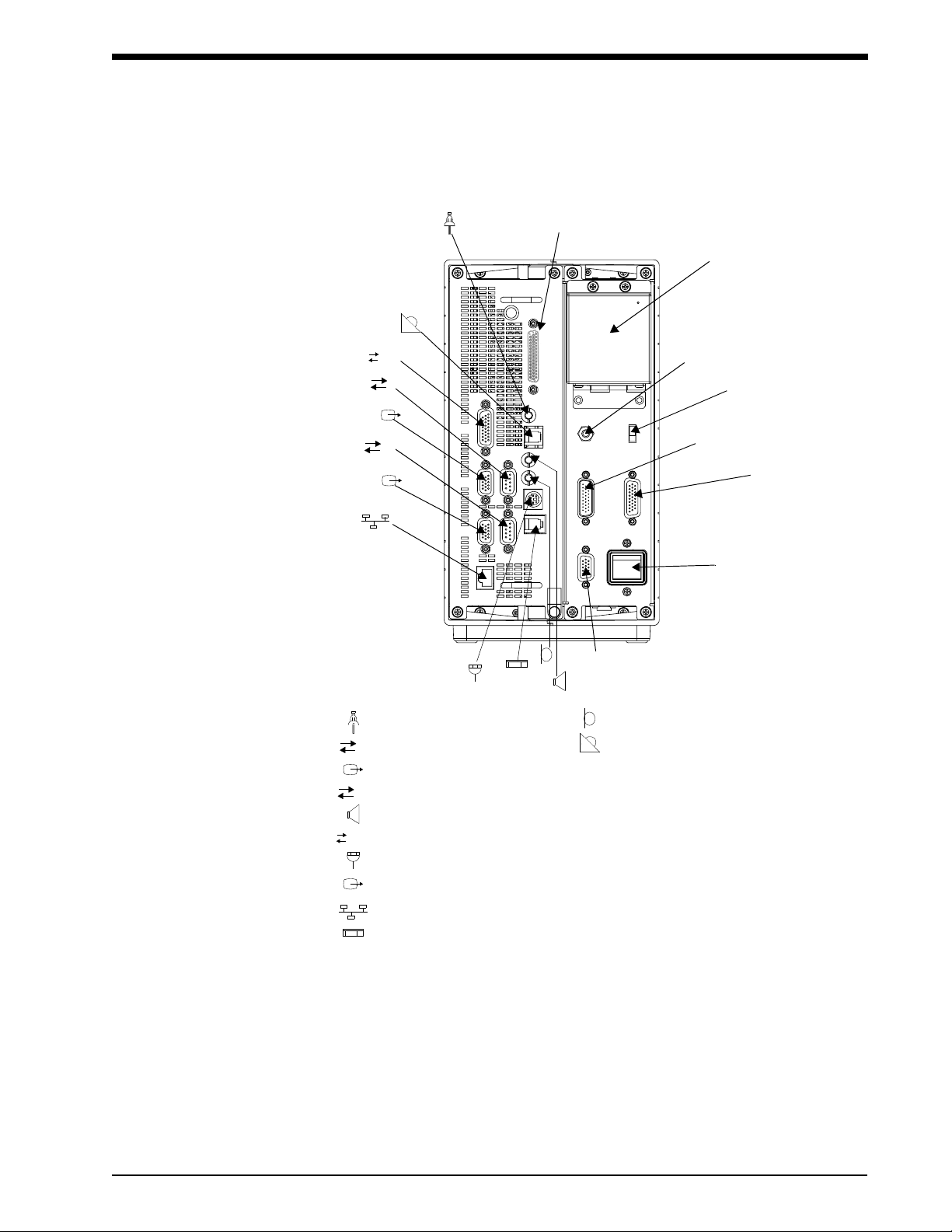
Ultraview 1700 (90387)
Figure 1-5: Rear view (90387)
1
SDLC
1
2
2
SDLC
Unavailable
Serial port 1
Video port 1
Serial port 2 (Touchscreen)
Audio output
SDLC/IO
Mouse
Video port 2
Ethernet (10BaseT)
External keyboard
Unavailable
Nurse alert
NiMH battery
Equipotential ground
SDLC terminator
SDLC/power input
SDLC/power output
Unit power switch
High level output
IRTS interface for 91416-B


2-1
Contents
Setup
Specifications
90385
Assembled weight of monitor: 36 lbs (16.4 kg)
Dimensions of monitor with pedestal at 0° tilt: 14 (H) × 14.5 (W) × 17.5 (D) in.
(35.6 × 36.8 × 44.5 cm)
Temperature (operating): +10° to 40° C (50° to 104° F)
Humidity (operating): 95% relative humidity, non-condensing
Total power dissipation: 180 watts; 615 BTU/hour
AC input voltage range: 100 to 120 V; 220 to 230 VAC
AC input current: 2.5 A @100 to120 VAC
3.15 A @ 220 to 230 VAC
AC input frequency range: 50 to 60 Hz
Specifications . . . . . . . . . . . . . . . . . . . . . . . . . . . . . . . . . . . . . . . . . . . . . . . . . . . . . . . . . . . . . . . . . . 1
Inspection . . . . . . . . . . . . . . . . . . . . . . . . . . . . . . . . . . . . . . . . . . . . . . . . . . . . . . . . . . . . . . . . . . . . . 2
Pre-Installation Testing. . . . . . . . . . . . . . . . . . . . . . . . . . . . . . . . . . . . . . . . . . . . . . . . . . . . . . . . . . . 3
Mounting. . . . . . . . . . . . . . . . . . . . . . . . . . . . . . . . . . . . . . . . . . . . . . . . . . . . . . . . . . . . . . . . . . . . . . 3
Installation . . . . . . . . . . . . . . . . . . . . . . . . . . . . . . . . . . . . . . . . . . . . . . . . . . . . . . . . . . . . . . . . . . . . 8
Network Configuration . . . . . . . . . . . . . . . . . . . . . . . . . . . . . . . . . . . . . . . . . . . . . . . . . . . . . . . . . . 13
System Configuration . . . . . . . . . . . . . . . . . . . . . . . . . . . . . . . . . . . . . . . . . . . . . . . . . . . . . . . . . . . 14
Biomed Setup Menu . . . . . . . . . . . . . . . . . . . . . . . . . . . . . . . . . . . . . . . . . . . . . . . . . . . . . . . . . . . . 20

UCW and Ultraview 1700 Monitors — Service Manual
2-2
90387
Inspection
Prior to installation of your patient monitor, conduct an equipment audit.
Upon receipt of the equipment, a detailed inventory must be taken to verify that the equipment
received matches your order. This inventory should include serial numbers, model numbers with
options, and cables. Carefully inspect these items for shipping damage. If damage is apparent,
notify the freight company and Spacelabs Medical immediately.
The monitors are typically shipped as follows:
UCW Monitor (90385) — Contains the monitor with installed I/O and CPU printed circuit board
assemblies (PCBAs), power cord, and AC cord retainer.
Ultraview 1700 Monitor (90387) — Contains the main assembly with installed I/O and CPU
printed circuit board assemblies (PCBAs), power cord, and AC cord retainer.
External Module Housing — The 90491 four-slot housing or the 90499 two-slot housing, DC
power supply, SDLC cables, and power cord.
Accessories — Contains the power cords and cable assemblies ordered.
Mounting Hardware — All ordered mounting hardware is supplied with appropriate instruction
sheets.
Assembled weight of monitor: 9.7 lbs (4.4 kg)
Assembled weight DC power supply: 1.8 lbs (0.8 kg)
Dimensions of monitor: 10.25 (H) × 6.0 (W) × 9.5 (D) in.
(26.0 × 15.2 × 24.1 cm)
Dimensions of DC power supply: 2.1 (H) × 4.0 (W) × 6.5 (D) in.
(5.3 × 10.2 × 16.5 cm)
AC input voltage range: 100 to 120 VAC, 200 to 230 VAC
AC input current: 1.5 A (maximum)
AC input frequency range: 50 to 60 Hz
Power supply output voltage: +18 VDC
Power supply output current: 4.25 A (maximum)
Temperature (operating): +10° to 40° C (50° to 104° F)
Humidity (operating): 95% relative humidity, non-condensing
Power dissipation: 100 watts, 342 BTU/hour
!• When removing items from the shipping container, make sure you remove ALL
components from each container.

Setup
2-3
Pre-Installation Testing
Before mounting the equipment, it is recommended that you first verify its operation as
follows:
1. Power ON the unit and let the power-on diagnostics run.
2. Look in the upper-left corner of the display for any diagnostic failures or other system errors.
The monitor will start up normally if no unacceptable diagnostic errors occur. Refer to
Troubleshooting on page 5-1 for more information on the diagnostics features if the monitor
does not start up normally.
3. Insert at least one parameter module for testing purposes.
4. Refer to Preventive Maintenance (PM) Procedures on page 4-3 and complete those
procedures.
Mounting
The monitor can be mounted in one of three ways:
Wall Mount — The unit is attached to an adjustable mounting arm that projects out from a wall
track. This mounting scheme is suitable for a bedside configuration.
Pedestal Mount — The unit is securely attached to a flat surface, such as a shelf or an
operating room cart.
Roll Stand — The unit can be easily rolled from one location to another.
The 90387 can also be operated unmounted in a free-standing, table-top configuration, or it can be
console-mounted.
For installation requirements of the module housing(s), refer to the Module Housings and Power
Supplies Service Manual (P/N 070-0680-xx, located on CD-ROM 084-0700-xx).
Base Tension Adjustment (90385)
The 90385 monitor’s base can be adjusted to increase or decrease the tension that allows tilting of
the monitor screen. Tension is factory-adjusted for optimum performance and further adjustment is
usually not necessary. If adjustment is necessary, turn the base screw clockwise (refer to
Figure 2-1) to increase base tension or counter clockwise to decrease tension. Set the tension
loosely enough to allow normal viewer adjustments, yet tightly enough to hold the adjusted position.

UCW and Ultraview 1700 Monitors — Service Manual
2-4
Figure 2-1: 90385 base tension adjustment
Wall Mounting
Figure 2-2: Bedside configuration
!• If necessary, base adjustment must be done prior to installing the monitor onto a
mount.
• Not all monitors will have the base tension adjustment described here.
!• Specific wall requirements for the installation of wall mounts are not covered in
this manual and are the responsibility of each hospital. Refer to the Module
Housings and Power Supplies Service Manual (P/N 070-0680-xx, located on
CD-ROM 084-0700-xx) for detailed instructions.
base tension adjusting screw
minimum of 60”
from floor
Ethernet connector
AC mains
10’ patient cable
patient bed
route all power cables
inside the wall track
90385, 91415, or 91418
90491 or 90387
power supply

Setup
2-5
The wall mounting hardware consists of:
Wall Track — The wall track is mounted vertically on the wall with the mounting arm installed in
the track. The mounting arm can be slid up and down in the wall track to the desired height. Wall
tracks are available in multiple lengths.
Wall Track End Caps — The wall track end caps are installed on the top and bottom of the wall
track to give the track a finished appearance and to prevent the equipment from sliding off the
end of the mounting track.
Mounting Arm — The mounting arm projects horizontally out from the wall track and holds the
display assembly and module housings. Two types of arms are available: one for a monitor-only
installation; the other for installation of the monitor and module housing(s).
Mounting Screws — Mounting screws are provided to install the end caps and to secure the
mounting arm at the desired vertical position.
Mounting Considerations
Power supply should be placed no closer than three inches (7.62 cm) to the remote housings to
allow sufficient air flow. Install a minimum of four AC outlets.
Pedestal Mounting (90385)
To attach the pedestal mount to the display assembly refer to Figure 2-3.
1. Verify that the pedestal’s six rubber feet and four retaining studs with retaining rings have
not been dislodged during shipping.
2. Carefully place the display on its side. A cushion should be used under the display to avoid
scratching the display case.
3. Rotate the display’s round base (if necessary) so that its tick mark points toward the front of
the unit.
4. Line up the four retaining studs on the pedestal with the four holes in the display’s round
base.
5. Push the pedestal onto the round base and secure it by turning each of the four retaining
studs 90 degrees clockwise with a straight blade screwdriver. The studs will lock in place
and can no longer be turned.
6. Carefully return the display to its normal upright position.
!• The monitor, monitor wall plate, and AC outlet must be located on the same side
of the patient bed. The power cord has a standard length of 10 feet (3.05 m).

UCW and Ultraview 1700 Monitors — Service Manual
2-6
Figure 2-3: Pedestal mount
Console Mounting (90387)
The physical layout and other console characteristics depend on the requirements of the hospital or
other institution. It is the responsibility of the institution to define its specific console needs and to
design and construct the console according to its specifications.
For this reason, Spacelabs Medical does not supply a pre-fabricated console assembly. Instead, this
section provides the information necessary to create a custom console design. In designing the
console, the following considerations must be kept in mind.
• Access
The rear of the console must be designed to allow for easy access. The dimensions of the rear
access door must allow the 90387 and display monitor to be easily installed and removed.
• Cooling
The console cabinet must be designed to allow sufficient air flow for natural convection.
If the console cabinet is enclosed, one of two cooling methods can be used:
Central Air Conditioning — The console can be connected directly to an air conditioning
cooling duct. The maximum ambient air temperature should be limited to approximately
32° C, and vented from the console at the highest exit.
!• The 90387 does not contain a fan.
rubber feet (6)
retaining
studs (4)
tick mark
This manual suits for next models
2
Table of contents
Other OSI Systems Medical Equipment manuals


