Aulisa Guardian Angel GA2000 Series User manual

Digital Vital Sign Monitoring System
Instructions For Use
____________________________________________________________
7MN00027-01
Guardian Angel®
GA2000 Series

1
Disclaimer
At the time of publication, this manual is believed to be accurate and up-to-date. In
the interest of continued product development, Taiwan Aulisa Medical Devices
Technologies, Inc. reserves the right to make changes and improvements to this
manual and the products described within at any time, without notice or obligation.
References to “Aulisa” in this manual shall imply Taiwan Aulisa Medical Devices
Technologies, Inc.
Aulisa is a registered trademark of Taiwan Aulisa Medical Devices Technologies, Inc.
Taiwan Aulisa Medical Devices Technologies, Inc.
No. 218-2, Chong Yang Rd., Nangang Dist.
11573 Taipei City , Taiwan
Tel.: +886 809 083 100
Distributed by
Aulisa Medical USA, Inc.
999 Commercial Street, Suite 208
Palo Alto, CA 94303,USA
Tel.: 1.833.828.5472
www.aulisa.com
© 2020 Taiwan Aulisa Medical Devices Technologies, Inc.
CAUTION!!! Read this entire manual carefully before using Guardian Angel®GA2000
Series Digital Vital Sign Monitoring System.

2
Table of Contents
Disclaimer.......................................................................................................................1
Guide to Symbols ...........................................................................................................4
Welcome ........................................................................................................................6
GA2000S Main Elements........................................................................................6
GA2000S Function..................................................................................................7
GA2000S Intended Use ..........................................................................................7
Precautions for Use........................................................................................................8
Device Components .......................................................................................................9
Device Overview ..........................................................................................................10
Display Unit ..........................................................................................................10
Receiver/Transponder..........................................................................................16
Audio/Video Feature............................................................................................17
Device Setting Up.........................................................................................................18
Device Connection .......................................................................................................21
Wi-Fi Network Initial Setup..................................................................................21
Wi-Fi Network Reset ............................................................................................22
Device Pairing...............................................................................................................23
Automatic Pairing.................................................................................................23
Pairing with a new Aulisa sensor module ............................................................23
Pairing with a new Receiver/Transponder...........................................................24
Device Verification .......................................................................................................26
Verify the device function....................................................................................26
Verify the alarm function BEFORE each use ........................................................26
Device Power Off..........................................................................................................27
Display Unit ..........................................................................................................27
Receiver/Transponder..........................................................................................27
Device Powering...........................................................................................................27
Display Unit ..........................................................................................................27
Receiver/Transponder..........................................................................................28
Alarms and Limits.........................................................................................................29
Alarm Features.....................................................................................................29
Alarm Limits .........................................................................................................33
Alarm Delay Feature (for Oximeter Module only) ...............................................37
Care and Maintenance.................................................................................................38
Troubleshooting ...........................................................................................................39
FCC Compliance ...........................................................................................................40

3
Service, Support, and Warranty...................................................................................42
Privacy Policy................................................................................................................43
Our Policy .............................................................................................................43
Changes................................................................................................................44
Specifications ...............................................................................................................51
Parts and Accessories...................................................................................................53

4
Guide to Symbols

5

6
Welcome
This manual will help you get started with monitoring using Aulisa Guardian Angel®
GA2000 Series Digital Vital Sign Monitoring System (“GA2000S”) by introducing the
Display Unit and the Receiver/Transponder which are intended for use in conjunction
with a variety of wearable Aulisa sensor module(s).
Refer to the Instructions for Use of Aulisa sensor module(s) for detailed instructions.
Adult/Pediatric Oximeter Module: 7MN00028-01
Infant Oximeter Module: 7MN00029-01
Thermometer Module: 7MN00030-01
GA2000S Main Elements
Display Unit – A self-contained tablet computer running Aulisa application
software wirelessly collects and displays vital sign data from the
Receiver/Transponder. It also generates alarms to alert users to technical errors
or physiological events.
Receiver/Transponder –A stand-alone device containing an audio/video
camera receives vital signs from Aulisa sensor module(s) and transmits data to
the Display Unit along with audio/video signals.
Adult/Pediatric Oximeter Module – A wireless and reusable device worn on the
finger measures and transmits SpO2and pulse rate data. It is composed of
Oximeter Box and Oximeter Sensor Cable.
Infant Oximeter Module – A wireless and reusable device worn on the foot
measures and transmits SpO2and pulse rate data.
Thermometer Module –An adhesive device attached to the chest and armpit
measures and transmits body temperature data wirelessly. It comprises
Thermometer Box and Sensor Patch. It is intended for adults, pediatrics, and
infants.
7
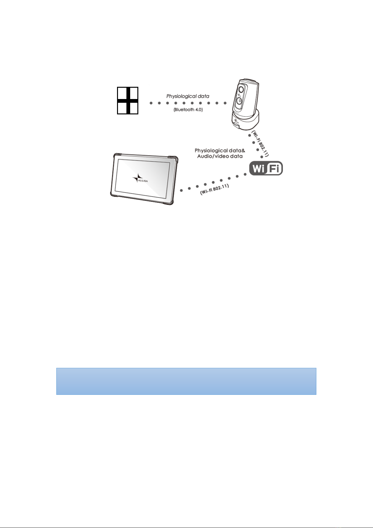
GA2000S Function
The Aulisa sensor module(s) is a wearable device intended for vital signs detection
and physiological data transmission to the Receiver/Transponder via Bluetooth
technology. The Receiver/Transponder communicates with the Display Unit through
a customer Wi-Fi network implemented and managed by end users. The Display Unit
receives and displays physiological data as well as generates alarms for technical
errors or physiological events.
GA2000S Intended Use
The Guardian Angel®GA2000 Series Digital Vital Sign Monitoring System is intended
to help those who are interested in keeping watch on oxygen saturation level (SpO2),
pulse rate (PR) and armpit body temperature of their loved ones. The Guardian Angel
is not intended for medical use.
Aulisa sensor module(s)
Display Unit
Receiver/
Transponder
NOTE: The GA2000S may come with different Aulisa sensor module(s) resulting in
different intended uses.

8
Precautions for Use
1. Use this device only within its designated range (approximately 32.8 feet (10
meters)— spherical radius— from Aulisa sensor module(s) to the
Receiver/Transponder). Moving outside this range may cause missing, lost,
and/or inaccurate data.
2. This device readings may be affected by the use of an electrosurgical unit.
3. If this device fails to respond as described, discontinue use until the situation is
corrected by qualified personnel.
4. Be careful with small parts that can be removed from the device and swallowed,
such as port covers. They are hazardous to children.
5. Do not use in or around water or any other liquid when AC power adaptor is
used.
6. Only use this device with charging adaptors provided by Aulisa.
7. Do not immerse any part of the device in any liquids.
8. Do not subject the device to extreme hot or cold temperatures, humidity, or
direct sunlight.
9. Follow local governing ordinances and recycling instructions regarding disposal
or recycling of the device and device components, including batteries.
10. Radios and cell phones or similar devices can affect the wireless connection of
the device and must be kept at least 6.5 feet (2 meters) away from the device.
11. System connection failure (Bluetooth/Wi-Fi wireless connection) may result in
loss of data transfer.

9
Device Components
Display Unit
with Aulisa application software
Receiver/Transponder
Display Unit Stand
Display Unit Charging Adapter (Type-C)
Receiver/Transponder
Charging Adapter (micro-USB)
Receiver/Transponder Clamp
Receiver/Transponder Sticker
Receiver/Transponder Velcro Strap

10
Device Overview
Display Unit
The Display Unit features a 10.1” LCD multi-touch display with Wi-Fi connectivity
capability. The Display Unit displays real-time vital signs measured by Aulisa sensor
module(s).
The Display Unit will display informational text messages, alarm text messages, and
beep made audible upon an alarm condition trigger event.
The Display Unit incorporates a talking and listening function that allows audio
messages to be received and sent via the Receiver/Transponder.
NOTE: It is recommended that the Display Unit be placed on the Display Unit Stand.
NOTE: Close the cover of charging port when the charging adapter is not in use.

11
Following tables describe the indicators and controls displayed on the Display Unit.
Display Icons and Indicators
Indicator
Name
Description
SpO
2
%
Blood Oxygen
This icon identifies the window
showing the functional blood
oxygen saturation in percent.
PR bpm
Pulse Rate
This icon identifies the window
showing the pulse rate in bpm.
TEMP°F
Body Temperature
This icon identifies the window
showing the body temperature
in either
°C or °F.
Hi
High temperature
This icon represents the
measured temperature is
higher than the upper limit of
the display range.
Lo
Low temperature
This icon represents the
measured temperature is
lower than the lower limit of
the display range.
No data
When the vital signs cannot be
measured, the Display Unit
shows dashes “- - -” in each of
the vital sign windows.
Bluetooth
Connection Status
This icon displays whether the
Aulisa sensor module(s) and the
Receiver/Transponder are
connected via Bluetooth. It will
turn blue once the pairing
succeeds.
Pulse Amplitude
(PA)
This icon displays the pulse
signal strength.
Measurement Site
Status
This icon displays whether
there is a finger inserted in the
Adult/Pediatric Oximeter
Module.

12
A system alarm will be
displayed on the Display Unit if
no fingers are detected.
Measurement
Site Status
This icon displays whether the
Infant Oximeter Module is
attached to the foot. A system
alarm will be displayed on the
Display Unit if no contact is
detected between the sensor
and the foot.
Motion Indicator
This animated icon detects
excessive motion of the
measurement site.
Sensor Cable
Connection Status
This icon indicates whether the
Oximeter Sensor Cable is
connected to the Oximeter Box.
A system alarm will be
displayed on the Display Unit if
the cable is disconnected.
Battery Level of
Display Unit
These icons signify the battery
level of the Display Unit.
A medium priority system alarm
will be displayed on the Display
Unit when the Display Unit
battery level is low.
Battery Level of
Aulisa sensor
module(s)
These icons signify the battery
level of Aulisa sensor module(s)
at Full, Medium, or Low.
A medium priority system alarm
will be displayed on the Display
Unit when the battery level is
low.
Receiver/
Transponder
Connection
Indicator
This icon indicates whether
there is a connection
established between the
Display Unit and the
Receiver/Transponder.
The icon turns blue with a

13
successful connection and red
when losing connection.
Wi-Fi Strength
Indicator
This icon indicates whether
there is a strong connection
between the Display Unit and
customer Wi-Fi Network.
Alarm Indicator
This icon identifies an alarm
condition exists.
“!!!” represents high priority.
“!!” represents medium priority.
Alarm Off
This icon indicates that the
alarm is turned off for the
corresponding physiological
condition.
Audio Paused
This icon indicates that the
alarm audio is silenced for 2
minutes.
Audio Off
This icon indicates that the
alarm audio is silenced
permanently.
Software Control Buttons
Button
Function
Description
System Settings
Tap on this button on the MAIN
screen to access the setting
menu of the system.
Edit Profile
Tap on this button on the MAIN
screen to edit profile, including
name, weight, gender, date of
birth, and location.
Alarm History
Tap on this button on the
MAIN screen to view the alarm
history list.
Sleep Mode
Tap on this button on the MAIN
screen to let the Display Unit
enter sleep mode. To wake up
the Display Unit, tap on the
blank screen and use finger to

14
swipe to the right.
Talking Function
Press and hold this button
on
the MAIN screen
to talk to the
person being monitored via
the Display Unit.
Listening Function
Tap on this button
on the
MAIN screen
to receive
audio of person being
monitored via the
Receiver/Transponder's
microphone.
Return to Previous
Screen
Tap on this button to return to
the previous page.
Connection Setup
In the Setting menu, tap on this
button to change the Wi-Fi
network of the Display Unit or
of the Receiver/Transponder,
and to modify the password for
the Receiver/Transponder.
Set Timezone
In the Setting menu, t
ap on this
button to select the correct
timezone.
Set Display
Brightness
In the Setting menu, t
ap on this
button to set the brightness of
the display.
Set Alarm Limits
In the Setting menu, tap on this
button to adjust the alarm
limits for each Aulisa sensor
module.
NOTE: The alarm limits are
adjustable only when the
wireless connection is
established.
Restore Default
Alarm Settings
In the Setting menu, tap on this
button to restore alarm limits
to manufacture-configured
values.

15
Establish Pairing
In the Setting menu, tap on this
button to pair to a new Aulisa
sensor module or
Receiver/Transponder either by
scanning the barcode or
manually keying in the code
found on the back of the said
device.
Pause Alarm Audio
This button appears when an
alarm is triggered. Tap on the
button to
temporarily
silence
the alarm audio of the current
triggered alarm event for 2
minutes.
Turn Off Alarm
Audio
The button appears when an
alarm is triggered. Tap on the
button to
permanently
silence
the alarm audio of the current
triggered alarm event.
Standby
The button appears when the
Infant Oximeter Module is
detached from the foot. Tap
on the button to return to the
“Before You Start” page.

16
Receiver/Transponder
The Receiver/Transponder features Bluetooth/Wi-Fi communication interfaces and
an audio/video camera. It receives vital signs monitoring data from the Aulisa sensor
module(s) via Bluetooth, integrates audio and video of the
person being
monitored
, and then converts the data to Wi-Fi signals, which are transmitted to
and displayed by the Display Unit.
The Aulisa sensor module(s) must be used within 32.8 feet (10 meters) to the
Receiver/Transponder.

17
Audio/Video Feature
Video
: View monitoring video
Listening
: Tap to turn on and receive monitoring audio
Talking
: Press and hold to send an audio message
NOTE: When personal privacy is desired, place the sticker over the camera and
microphone of Receiver/Transponder. The sticker completely blocks the image
but may not significantly block the sound.

18
Device Setting Up
Before you begin your monitoring session, unpack the Display Unit and
Receiver/Transponder and become familiar with their parts.
Step 1: Connect the charging adaptor (micro-USB end) to the Receiver/Transponder
and a power outlet.
Step 2: You may simply place the Receiver/Transponder on a table or follow the
instructions below to assemble the holder and the clamp so that the
Receiver/Transponder can be clamped onto the furniture or hung on the
wall.
Clamp onto the furniture
(a) Pull down the clip and slide
the Clamp into the Hold er.
(b) Ensure the Clamp is stable.
(c) Secure the Clamp onto the
furniture. Place the
Receiver/Transponder body on
the Hol de r.
(d) Secure the power cable to the
Holder with Velcro strap.

19
Hang on the wall
(a) Slide the Clamp into the
Holder.
(b) Hang the Holder on the wall.
(c) Ensure the Holder is secure.
Place the
Receiver/Transponder body on
the Hol de r.
(d) Secure the power cable to the
Holder with Velcro strap.
Step 3: Press and hold the Power button for three (3) seconds to turn on the
Receiver/Transponder.
Step 4: Connect the charging adaptor (Type-C end) to the Display Unit and a power
outlet.
NOTE:
Securing the power cable to the holder with the Velcro strap prevents the
Receiver/Transponder body from dropping to the ground.
CAUTION!!! Always keep the Receiver/Transponder plugged in.
NOTE: The power LED will light green when the power is on.
This manual suits for next models
1
Table of contents
Other Aulisa Medical Equipment manuals

Aulisa
Aulisa Guardian Angel Rx GA1001 User manual

Aulisa
Aulisa Guardian Angel Rx GA1000 User manual

Aulisa
Aulisa Guardian Angel Rx GA2000 User manual

Aulisa
Aulisa Guardian Angel Rx Guardian Angel Rx Lite GA2000... User manual

Aulisa
Aulisa Guardian Angel Rx GA2000 User manual

Aulisa
Aulisa Guardian Angel GA1000 Series User manual


