GHM DeltaOhm HD402 Series User manual

Operating manual
Pressure transmitters
Pressure ON/OFF relay switches
HD402… series
www.deltaohm.com
English
Keep for future reference.

HD402… - 2 - V1.1
TABLE OF CONTENTS
1 INTRODUCTION .................................................................................................... 3
2 TECHNICAL CHARACTERISTICS ............................................................................ 4
3 INSTALLATION .....................................................................................................
3.1 ELECTRICAL CONNECTIONS ..................................................................................... 8
3.2 EXAMPLE OF CONNECTION WITH THE INDICATOR CONTROLLER HD9022 ................................. 9
4 CONFIGURATION ................................................................................................ 11
4.1 CONFIGURATION OF THE MODELS WITH ANALOG OUTPUT HD402[A]T…) ............................ 11
4.2 CONFIGURATION OF THE MODELS WITH RS485 OUTPUT HD402ST…) ............................... 14
4.3 CONFIGURATION OF THE MODELS WITH RELAY OUTPUT HD402TR…) ................................. 16
4.4 ERROR MESSAGES ON DISPLAY ............................................................................... 19
5 ALARM OPERATING MODES (HD402TR…) ........................................................... 20
MODBUS-RTU PROTOCOL (HD402ST…) .............................................................. 22
7 INSTRUMENT STORAGE ...................................................................................... 24
8 SAFETY INSTRUCTION ........................................................................................ 24
9 ACCESSORIES ORDERING CODES ....................................................................... 25

HD402… - 3 - V1.1
1INTRODUCTION
The HD402… series is composed of pressure transmitters and pressure ON/OFF relay
switches. The instruments measure relative pressure with respect to atmosphere or
differential pressure in the range from 50 Pa to 200 kPa depending on model) by us-
ing a silicon piezoresistive sensor with high accuracy and temperature compensation,
which allows excellent linearity, repeatability and stability over the time.
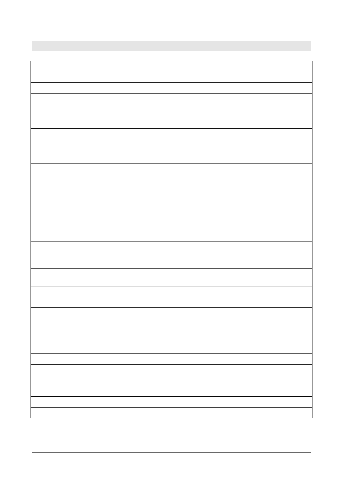
Thanks to the particular sensor used, the instruments are insensitive to the mounting
orientation and position. Moreover, the high stability of the sensor over the time and
in comparison to the changes in temperature allows eliminating the operations of
maintenance typically required to compensate for the aging and the deviation of the
sensor zero. The auto-zeroing feature in the HD402TR1L low range model allows sta-
ble measurements over the time without the need to recalibrate.
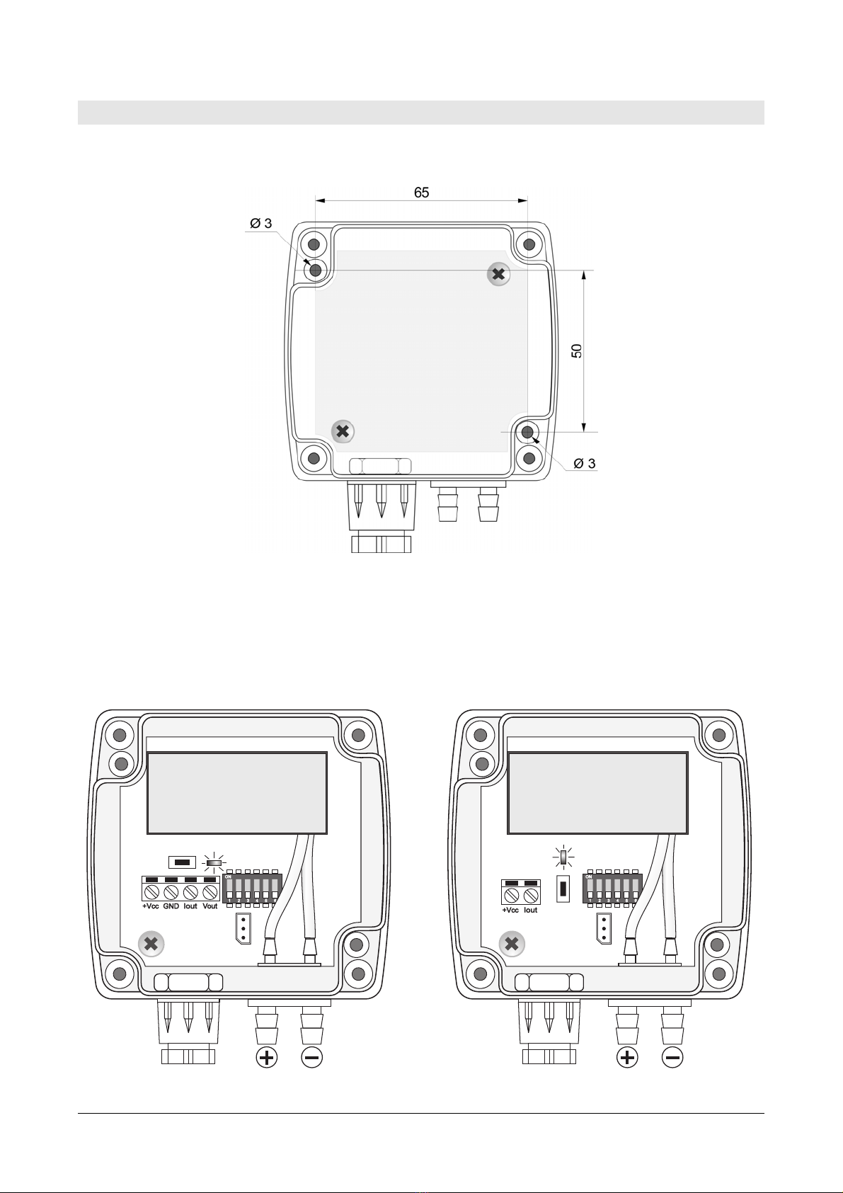
Available outputs, depending on the model:
•RS485 Modbus–RTU digital output HD402ST…);
•0...10 V voltage analog output HD402T…);
•0...20 mA / 4...20 mA active current analog output HD402T…);
•2-wire current loop) 4...20 mA analog output HD402AT…);
•ON/OFF relay switch HD402TR…L).
Different units of measurement can be chosen for each model and, in the models with
analog output, it is possible to choose the full scale f.s.) value for the output high,
intermediate or low range) and set the unipolar 0...+f.s.) or bipolar -f.s....+f.s.)
measuring range.
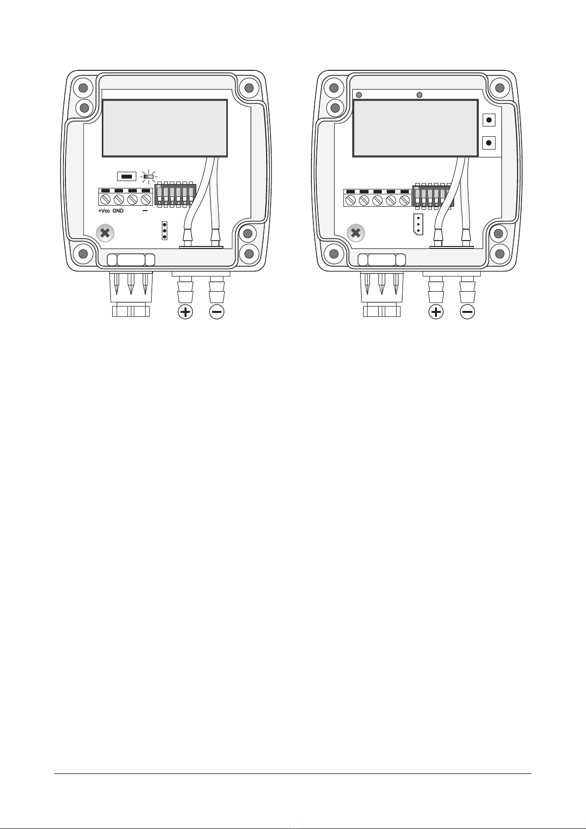
Versions with optional 4-digit LCD display option L) are available, which allow the
measured parameters to be displayed. The pressure relay switches always include the
display.
The configuration can be made by connecting the serial port of the instrument to the
PC or by means of the quick configuration dip switches on the circuit board. The ver-
sions with relay switch output are equipped with two internal buttons for the configura-
tion via display.
The instruments are factory calibrated and ready for use.
Models
HD402
“” = without LCD except HD402TR…)
L = with LCD
1 = range ± 250 Pa / 25 mmH2O / 1 inchH2O / 2,5 mbar
2 = range ± 1000 Pa / 100 mmH2O / 4 inchH2O / 10 mbar
3 = range ± 10 kPa / 50 mmHg / 1,5 PSI / 100 mbar
4 = range ± 100 kPa / 500 mmHg / 15 PSI / 1000 mbar
5 = range ± 200 kPa / 1000 mmHg / 30 PSI / 2000 mbar
T = 0…10 V and 0/4…20 mA active analog output
AT = 2-wire 4…20 mA analog output
ST = RS485 Modbus-RTU digital output
TR = ON/OFF relay switch output

HD402… - 4 - V1.1
2TECHNICAL CHARACTERISTICS
Sensor Piezoresistive, High stability
Measuring range See table 2.1
Resolution See table 2.2
Accuracy (*) •HD402TR1…: ± 0.8% measure + 0.5 Pa) @ 0…50 °C
•HD402…T1…: ±1.5% FSS @ 25 °C / ± 3% FSS @ 0…50 °C
•HD402…2…: ±0.75% FSS @ 25 °C / ± 1% FSS @ 0…50 °C
•HD402…3… / HD402…4… / HD402…5…: ±1% FSS @ 0…50 °C
Long term stability
1000 h) @ 25 °C
•HD402TR1…: ±0,2 Pa with auto-zero
•HD402…T1… / HD402…2…: ±0.5% FSS
•HD402…3…: ±0.35% FSS
•HD402…4…/ HD402…5…: ±0.25% FSS
Output •HD402T…: Active analog 0…10 Vdc RLmin = 10 kΩ
) or 0/4…20 mA
RLmax = 500 Ω)
•HD402AT…: 2-wire current loop) 4…20 mA RLmax = Vcc-12)/0,022)
•HD402ST…: Digital RS485 Modbus-RTU
•HD402TR…: SPDT Relay switch, 3 A/250 Vac, 3 A/30 Vdc resistive
load
Alarm only HD402TR) Front LED, internal buzzer, relay switch
Response time 0.5 seconds for the display updating
For transmitters: configurable 0.125, 1, 2 or 4 seconds for the output
Overpressure limit •HD402…1… / HD402…2… / HD402…3…: 50 kPa
•HD402…4…: 200 kPa
•HD402…5…: 400 kPa
Connection to PC RS232 serial port
Can be connect to a USB port by using the optional CP27 adapter
Zero calibration Automatic for HD402TR1L, manual for the other models
Compatible media Only air and non-aggressive dry gases
Power supply •HD402T…: 24 Vac ± 10% o 18…40 Vdc
•HD402AT… and HD402ST…: 12…30 Vdc
•HD402TR…:24 Vac ± 10% o 15…36 Vdc
Absorption •HD402T…, HD402AT… and HD402TR…: < 1 W @ 24 Vdc
•HD402ST…: < 100 mW @ 12 Vdc
Pressure connection Ø 6.2 mm
Electrical connections Screw terminal block, max 1.5 mm2 , PG9 cable gland
Operating conditions -10…+60 °C / 0…95% RH
Storage temperature -20…+70 °C
Housing dimensions 80 x 84 x 44 mm
Protection degree IP65
(*) FSS = nominal range = 2 x f.s. high range).

HD402… - 5 - V1.1
TAB. 2.1: full scale (f.s.) values and units of measurement
Model Pa kPa mbar mmH2O inchH2O
mmHg PSI
HD402…1…
50/100/250 --- 0.5/1/2.5 5/10/25 0.2/0.4/1
--- ---
HD402…2…
250/500/1000
--- 2.5/5/10 25/50/100
1/2/4 --- ---
HD402…3…
--- 2.5/5/10 25/50/100 --- --- 10/25/50 0.4/0.75/1.5
HD402…4…
--- 25/50/100
250/500/1000
--- --- 100/250/500
4/7.5/15
HD402…5…
--- 50/100/200
500/1000/2000
--- --- 250/500/1000
10/15/30
The instrument range is ±f.s.; the low and intermediate ranges are only for the models with
analog output, the models with RS485 and relay output always have the high range. The range
0…+f.s. for the output can be set in the models with analog output the range on display is al-
ways –f.s….+f.s. high range).
TAB. 2.2: resolution
Model Pa kPa mbar mmH2O inchH2O mmHg PSI
HD402…1…
0.1 --- 0.001 0.01 0.001 --- ---
HD402…2…
1 --- 0.01 0.1 0.01 --- ---
HD402…3…
--- 0.01 0.1 --- --- 0.01 0.001
HD402…4…
--- 0.1 1 --- --- 0.1 0.01
HD402…5…
--- 0.1 1 --- --- 1 0.01
DIMENSIONS

HD402… - 6 - V1.1
3INSTALLATION
By opening the lid, 3 mm diameter holes are available so to allow securing the base of
the instrument directly to a panel or to the wall.
Internally there are:
•the terminal header for connecting the power supply and the output;
•the RS232 serial connector COM AUX, except HD402ST…);
•the dip switches for quick configuration.
•The CAL ZERO button except HD402TR…) or the B1 and B2 buttons for the con-
figuration via display only HD402TR…).
COMAUX
123456
ON
POWER SUPPLY
& OUTPUT
CAL ZERO
LED DIP SWITCH
1 2 3 4 5 6
LCD
LED DIP SWITCH
CAL ZERO
COMAUX
1 2 3 4 5 6
ON
1 2 3 4 5 6
POWER SUPPLY
& OUTPUT
LCD
Models with active analog output
(HD402T…)
Models with 2-wire current output
(HD402AT…)

HD402… - 7 - V1.1
1 2 3 4 5 6
ON
+
RS485
OUTPUT 120 ohm
OPEN
RT
CAL ZERO
LED 485
ADDRESS SETTING
1 2 3 4 5 6
LCD
POWER
COM AUX
DIP SWITCH
POWER SUPPLY
& OUTPUT
NO NC COM +Vdc GND
B1
B2
1 2 3 4 5 6
ON
1 2 3 4 5 6
LCD
POWER LED ALARM LED
Models with digital RS485 output
(HD402ST…)
Models with relay switch output
(HD402TR…)
The instruments can be mounted in any position, but typically they are fixed on a ver-
tical wall with the pressure inputs facing down.
The deviation of the zero due to the mounting position can be corrected by using the
CAL ZERO button except HD402TR…) or the B1 and B2 buttons only HD402TR…). In
the model HD402TR1L, an auto-zero circuit periodically automatically equalizes the
differential pressure at the input of the sensor and corrects the offset due to the
mounting position or sensor aging.
To manually calibrate the zero, disconnect both the tubes from the + and – pressure
inputs, then proceed as follows:
Zero manual calibration in the models with CAL ZERO button:
•press CAL ZERO until the red LED starts flashing;
•when the red LED turns off, the zeroing procedure is completed: reconnect the
tubes to the pressure inputs.
Zero manual calibration in the models HD402TR…:
•Press B1 and B2 buttons at the same time until the ALARM red LED lights up if it
was not already on because of an alarm condition) and the instrument displays the
model information and the UP and DOWN arrows on the left of the LCD.
•When the instrument returns to the measurement mode displaying zero reading,
reconnect the tubes to the pressure inputs.
If necessary, the manual auto-zero procedure can be performed also in HD402TR1L
in this case it is not necessary to disconnect the tubes from the pressure inputs).
Except for HD402TR1L in which the auto-zero procedure is periodic and automatic), it
is recommended to follow the auto zero procedure at least once a year under normal
operating conditions.

HD402… - 8 - V1.1
3.1 ELECTRICAL CONNECTIONS
Active current analog output Voltage analog output
2-wire current analog output Relay output
In the models with relay output, at power on, the alarm LED blinks quickly while the in-
strument information is displayed.
RS485 connection
In the RS485 connection, the instruments are connected in a sequence through a
shielded cable with twisted pair for signals and a third wire for the common. Line ter-
mination must be set at the two network ends.
The maximum number of devices that can be connected to the RS485 line Bus) de-
pends on the load characteristics of the devices to be connected. The RS485 standard
requires that the total load does not exceed 32 unit loads. The load of an HD402ST…
transmitter is equal to ¼ of unit load. If the total load is greater than 32 unit loads, di-
vide the network into segments and add a signal repeater between a segment and the
successive one. Line termination should be applied at both ends of each segment.
The instrument has a built-in line termination that can be connected or removed
through a short jumper placed next to the terminal block. If the instrument is the last
or the first device of a network group, connect the termination placing the short
jumper between the “RT” and “120 ohm” indications. If the instrument is not at the
Power supply Power supply
Power supply
Power supply
Other sensors with
RS485 output
Termination
Termination
PLC, data logger or
RS485/USB or RS485/RS232
converter for PC
Power supply

HD402… - 9 - V1.1
end of a network group, remove the termination placing the short jumper between the
“RT” and “OPEN” indications.
The cable shield must be connected to both line ends. The cable should have the fol-
lowing features:
•Characteristic impedance: 120 ohm
•Capacity: less than 50pF/m
•Resistance: less than 100 ohm/km
•Gauge: 0,22 mm2 AWG24) at least
The cable maximum length depends on baud rate and cable characteristics. Typically,
the maximum length is 1200 m. The data line must be kept separated from any power
lines in order to prevent interferences on the transmitted signal.
3.2 EXAMPLE OF CONNECTION WITH THE INDICATOR CONTROLLER HD9022
0…20 or 4…20 mA active current output
0…10 Vdc Voltage output
Power supply
Power supply

HD402… - 10 - V1.1
2-wire (current loop) 4…20 mA output

HD402… - 11 - V1.1
4CONFIGURATION
4.1 CONFIGURATION OF THE MODELS WITH ANALOG OUTPUT (HD402[A]T…)
Setting the configuration mode: the transmitter can be configured by using the dip
switches on the circuit board or via the serial communication port COM AUX. The choice
of the configuration mode is done with the dip switch dip switch 1:
•Dip switch 1 = ON the configuration set through the dip switches 2...6 is
used
•Dip switch 1 = OFF the configuration set via serial port is used
Configuration via dip switches:
The configuration of the dip switches is used by the transmitter only if the dip switch 1 is
ON. A dip switch is ON if placed up, towards the DIP SW sign.
Dip switches 2, 3: selection of the low/intermediate/high range for the analog output.
Dip switches 4, 5: selection of the unit of measurement.
Dip switch 6: setting of the unipolar 0...+f.s.) or bipolar -f.s...+ f.s.) measuring range
for the analog output.
The following tables report, for each model, the measuring range corresponding to the
analog outputs according to dip switches position.
TAB. 4.1: measuring ranges for the analog output in the models HD402[A]T1
Dip switch number
2 3 4 5 4 5 4 5 4 5
OFF OFF ON OFF OFF ON ON ON
Pa mmH2O inchH2O mbar
OFF
OFF ON 0…50 0…5 0…0.2 0…0.5
ON OFF 0…100 0…10 0…0.4 0…1
OFF OFF 0…250 0…25 0…1 0…2.5
ON ON
ON
OFF ON -50…+50 -5…+5 -0.2…+0.2 -0.5…+0.5
ON OFF -100…+100 -10…+10 -0.4…+0.4 -1…+1
OFF OFF -250…+250 -25…+25 -1…+1 -2.5…+2.5
ON ON
TAB. 4.2: measuring ranges for the analog output in the models HD402[A]T2
Dip switch number
2 3 4 5 4 5 4 5 4 5
OFF OFF ON OFF OFF ON ON ON
Pa mmH2O inchH2O mbar
OFF
OFF ON 0…250 0…25 0…1 0…2.5
ON OFF 0…500 0…50 0…2 0…5
OFF OFF 0…1000 0…100 0…4 0…10
ON ON
ON
OFF ON -250…+250 -25…+25 -1…+1 -2.5…+2.5
ON OFF -500…+500 -50…+50 -2…+2 -5…+5
OFF OFF -1000…+1000 -100…+100 -4…+4 -10…+10
ON ON

HD402… - 12 - V1.1
TAB. 4.3: measuring ranges for the analog output in the models HD402[A]T3
Dip switch number
2 3 4 5 4 5 4 5 4 5
OFF OFF ON OFF OFF ON ON ON
kPa mmHg PSI mbar
OFF
OFF ON 0…2.5 0…10 0…0.4 0…25
ON OFF 0…5 0…25 0…0.75 0…50
OFF OFF 0…10 0…50 0…1.5 0…100
ON ON
ON
OFF ON -2.5…+2.5 -10…+10 -0.4…+0.4 -25…+25
ON OFF -5…+5 -25…+25 -0.75…+0.75 -50…+50
OFF OFF -10…+10 -50…+50 -1.5…+1.5 -100…+100
ON ON
TAB. 4.4: measuring ranges for the analog output in the models HD402[A]T4
Dip switch number
2 3 4 5 4 5 4 5 4 5
OFF OFF ON OFF OFF ON ON ON
kPa mmHg PSI mbar
OFF
OFF ON 0…25 0…100 0…4 0…250
ON OFF 0…50 0…250 0…7.5 0…500
OFF OFF 0…100 0…500 0…15 0…1000
ON ON
ON
OFF ON -25…+25 -100…+100 -4…+4 -250…+250
ON OFF -50…+50 -250…+250 -7.5…+7.5 -500…+500
OFF OFF -100…+100 -500…+500 -15…+15 -1000…+1000
ON ON
TAB. 4.5: measuring ranges for the analog output in the models HD402[A]T5
Dip switch number
2 3 4 5 4 5 4 5 4 5
OFF OFF ON OFF OFF ON ON ON
kPa mmHg PSI mbar
OFF
OFF ON 0…50 0…250 0…10 0…500
ON OFF 0…100 0…500 0…15 0…1000
OFF OFF 0…200 0…1000 0…30 0…2000
ON ON
ON
OFF ON -50…+50 -250…+250 -10…+10 -500…+500
ON OFF -100…+100 -500…+500 -15…+15 -1000…+1000
OFF OFF -200…+200 -1000…+1000 -30…+30 -2000…+2000
ON ON
Configuration via the serial port COM AUX:
The configuration set with the serial communication is used by the transmitter only if
the dip switch 1 is OFF.
In order to modify the settings, please proceed as follows:
•Connect the serial COM AUX output of the transmitter to the RS232 port via the

HD402… - 13 - V1.1
RS27 cable) or USB via the cable CP27) of the PC. If you use the CP27 cable, in-
stall the USB drivers on your PC.
•On the PC, run a serial communication software, set the baud rate to 115200
and the communication parameters to 8N1.
•Send the commands given in table 4.6 to set the measurement range corre-
sponding to the analog outputs.
TAB. 4. : configuration serial commands models with analog output)
Command
Response
Description
Kn & Set the unit of measurement of index n
HD402T1 & HD402T2 HD402T3 & HD402T4 & HD402T5
n=0 Pa n=0 kPa
n=1 mmH2O n=1 mmHg
n=2 inchH2O n=2 PSI
n=3 mbar n=3 mbar
Rn & Set the measuring range of index n
n=0 high range e.g. 250 Pa /… in HD402T1)
n=1 intermediate range e.g. 100 Pa /… in HD402T1)
n=2 low range e.g. 50 Pa /... in HD402T1)
PU & Set the unipolar measuring range 0…+f.s.)
PB & Set the bipolar measuring range -f.s.…+f.s.)
Sn & Set the response time of index n for the analog outputs
n=0 0.125 s n=1 1 s n=2 2 s n=4 4 s
U0 & Set the interval 0…20 mA for the analog active current output
U1 & Set the interval 4…20 mA for the analog active current output
In order to read the settings of the transmitter, send the commands described in Ta-
ble 4.7.
TAB. 4.7: serial commands to read the configuration models with analog output)
Command
Response Description
G0 See the example
below
It reads the current configuration of the transmitter.
If the dip switch 1 is OFF, it returns the configuration set via
the serial port. If the dip switch 1 is set to ON, it returns the
configuration set by dip switch
GF See the example
below
It reads the configuration set by the serial port
GS See the example
below
It reads the configuration set by the dip switch
S? Response time It reads the response time set for the analog outputs
The commands G0, GF and GS for reading the configuration return a string consisting
of:
•model
•full scale value set for the analog outputs
•polarity of the measuring range U=unipolar, B=bipolar)
•range of the analog output current 0=0...20mA, 4=4...20 mA)
for example: the string "HD402T2 5.00mbar B40" indicates that the transmitter model
is HD402T2, the full scale set for the analog outputs is 5.00 mbar, the measuring
range is bipolar -5.00…+5.00 mbar) and the analog current output type is 4...20 mA.
The last character of the string 0 in the example) is a confidential code.

HD402… - 14 - V1.1
4.2 CONFIGURATION OF THE MODELS WITH RS485 OUTPUT (HD402ST…)
RS485 Modbus address: each transmitter of the network is univocally identified by
an address between 1 and 247. Transmitters having the same address shall not
be present in the network. The transmitter Modbus address is equal to the sum of
the value set with the dip-switches 2…6 value settable from 0 to 31) and the value set
with the serial command WA value settable from 1 to 216, default = 1). By setting a
dip-switch to ON upwards), the following values are added to the address:
Dip-switch 2
Dip-switch 3
Dip-switch 4
Dip-switch 5
Dip-switch
ON 16 8 4 2 1
OFF 0 0 0 0 0
Example: if the dip-switches 2 and 4 are set to ON, and the dip-switches 3,5 and 6
are set to OFF, the value set with the dip-switches is 16+4=20. If the value set with
the serial command WA is 1 default value), the transmitter Modbus address is
20+1=21.
The dip-switches can be set even if the transmitter is powered, and the change is ef-
fective immediately.
Configuration via the RS485 serial port:
The transmitters are pre-set by the factory. To change the settings, proceed as fol-
lows:
•Connect the transmitter RS485 output to the PC RS232 through a RS485/RS232
converter) or USB through a RS485/USB converter, for example the RS48 ca-
ble) port. If a RS485/USB converter is used, install in the PC the related USB
drivers.
•To enable the configuration mode, set the dip-switch 1 the one closest to the
terminal block) to ON upwards), then power the transmitter.
Note: the dip-switch 1 can be changed from OFF to ON even when the instru-
ment is powered; in this case it is however necessary, after setting the dip-
switch to ON, to press briefly less than 0.5 seconds) the CAL ZERO button to
enable the configuration mode the transmitter model information appears on
display, if present). Alternatively, power cycle the transmitter.
•On the PC, run a serial communication software, set the baud rate to 57600 and
the communication parameters to 8N1.
•Send the CAL START command the command is required to change the config-
uration; to read the value of the parameters, the command is not required).
•Send the commands given in table 4.8 to set or read the configuration parame-
ters of the transmitter.
TAB. 4.8: serial commands models with RS485 Modbus-RTU output)
Command
Description
Response time
AVGn Set the response time of index n for the measurement
n=0 0.125 s n=1 1 s n=2 2 s n=4 4 s
AVG? Reads the response time set for the measurement
Unit of measurement
DU0 Shows pressure in Pa HD402ST1 and HD402ST2) or kPa HD402ST3,
HD402ST4 and HD402ST5) on display

HD402… - 15 - V1.1
Command
Description
DU1 Shows pressure in mmH2O HD402ST1 and HD402ST2) or mmHg HD402ST3,
HD402ST4 and HD402ST5) on display
DU2 Shows pressure in inchH2O HD402ST1 and HD402ST2) or PSI HD402ST3,
HD402ST4 and HD402ST5) on display
DU3 Shows pressure in mbar on display
Modbus parameter
WA n…n Sets the Modbus base address to the value n…n
The value must be between 1 and 216 default = 1)
Warning: the actual Modbus address of the transmitter is equal to the
base address set with this command plus the value set with the dip-
switches.
Note: in the reply to the command, the previous actual address appears; the new
address will appear in the replies to the next commands.
BAUD r…r Sets the Modbus Baud Rate to the value r…r
The acceptable values are 9600 and 19200 default = 19200)
If the command is sent without the parameter r…r, the current setting is obtained
PAR p Sets the Modbus communication parameters of index p
p=O 8O1 p=N 8N2 p=E 8E1
If the command is sent without the index p, the current setting is obtained de-
fault = 8E1).
Note: the replies of the transmitters with RS485 Modbus-RTU output always start
with the address of the connected transmitter. For example, sending the AVG2 com-
mand to a transmitter with Modbus address 1, the reply is “001: averaging = 2 sec”.
To exit the configuration mode after sending the CAL START command, send the
CAL END command the transmitter automatically exits the configuration mode after 5
minutes from the last command sent).

HD402… - 16 - V1.1
4.3 CONFIGURATION OF THE MODELS WITH RELAY OUTPUT (HD402TR…)
The instrument can be configured by using the dip switches for the unit of measure-
ment) and the buttons for alarm settings) on the circuit board or via the COM AUX se-
rial port. The choice of the configuration mode is done with the dip switch 1:
•Dip switch 1 = ON the configuration set through the dip switches 4/5
and the buttons is used
•Dip switch 1 = OFF the configuration set via serial port is used
Configuration via dip switches:
The configuration of the dip switches is used by the instrument only if the dip switch 1 is
ON. A dip switch is ON if placed up, towards the DIP SW sign.
The following tables report the unit of measurement corresponding to the dip switches
setting.
TAB. 4.9: selection of the unit of measurement via dip switches
Models TR1 e TR2 Models TR3, TR4 e TR5
Dip switch
number Unit of
measurement
Dip switch
number Unit of
measurement
4 5 4 5
OFF ON inchH2O OFF ON PSI
ON OFF mmH2O ON OFF mmHg
OFF OFF Pa OFF OFF kPa
ON ON mbar ON ON mbar
The dip switches 2, 3 and 6 are not used.
CONFIGURATION VIA THE COM AUX SERIAL PORT:
The configuration set with serial communication is used by the instrument only if the
dip switch 1 is OFF.
In order to modify the settings, proceed as follows:
• Connect the COM AUX serial port of the instrument to the RS232 port via the
RS27 cable) or USB via the cable CP27) of the PC. If you use the CP27 cable, in-
stall the USB drivers on your PC.
• On the PC, run a serial communication software, set the baud rate to 115200
and the communication parameters to 8N2.
• Send the CAL START command the command is required to change the config-
uration; to read the value of the parameters, the command is not required).
• Send the commands given in the table below to set or read the instrument pa-
rameters

HD402… - 17 - V1.1
TAB. 4.10: serial commands models with relay output)
Command Description
G0 Reads the instrument model and range
Example of reply: HD402TR2 1000Pa
If the model has the Auto-zero feature, AZ will appear after the range
G2 Reads the instrument serial number
G3 Reads the instrument firmware version
G4 Reads the instrument firmware date
GD Reads the instrument calibration date
GM Reads the current measurement
Kn Sets the unit of measurement
HD402TR1 and HD402TR2:
n=0 Pa; n=1 mmH2O; n=2 inchH2O; n=4 mbar
HD402TR3, HD402TR4 and HD402TR5:
n=0 kPa; n=1 mmHg; n=2 PSI; n=4 mbar
Default: Pa HD402TR1 / HD402TR2), kPa HD402TR3 / HD402TR4 / HD402TR5)
AWSn Sets the relay operating mode
n=0 Negative NC contact is closed if no alarm, NO contact is closed if in alarm)
n=1 Positive NO contact is closed if no alarm, NC contact is closed if in alarm)
Default: Negative
ARS Reads the relay operating mode
AWBn Sets the buzzer activation status: n=0 OFF; n=1 ON
Default: OFF
ARB Reads the buzzer activation status
AWAn Sets the alarm activation status: n=0 OFF; n=1 ON
Default: OFF
ARA Reads the alarm activation status
AWEn Sets the alarm operating mode
n=0 Above threshold alarm is on if measurement is greater than threshold 1)
n=1 Below threshold alarm is on if measurement is less than threshold 1)
n=2 Outside thresholds alarm is on if measurement is less than threshold 1
or greater than threshold 2)
Default: Above threshold
ARE Reads the alarm operating mode
AWT1snnnn
Sets the threshold 1 value to snnnn “s” is the sign of the value) (*)
Default: pressure value corresponding to 30% of the full scale
ART1 Reads the threshold 1 value
AWT2snnnn
Sets the threshold 2 value to snnnn “s” is the sign of the value) (*)
Default: pressure value corresponding to 70% of the full scale
ART2 Reads the threshold 2 value
AWHnnnn Sets the hysteresis value to nnnn (*)
Default: pressure value corresponding to 10% of the full scale
ARH Reads the hysteresis value
AWD1nnn Sets the alarm activation delay to nnn seconds 0… 600 s)
Default: 0

HD402… - 18 - V1.1
Command Description
ARD1 Reads the alarm activation delay value
AWD2nnn Sets the alarm deactivation delay to nnn seconds 0… 600 s)
Default: 0
ARD2 Reads the alarm deactivation delay value
(*) The thresholds and hysteresis values are considered in the unit of measurement set in
the instrument. The value must be written without the decimal point, even if it is not an
integer value e.g., to set thresholds 1 to +1.500, write AWT1+1500). Leading zeros can
be omitted e.g., to set thresholds 1 to +0.050, write AWT1+50).
To exit the configuration mode after sending the CAL START command, send the CAL
END command the instrument automatically exits the configuration mode after 5
minutes from the last command sent).
CONFIGURATION VIA THE INTERNAL BUTTONS
The configuration set with the internal buttons is used by the instrument only if the
dip switch 1 is ON.
The upper button B1 allows scrolling the available operating parameters, while the
lower button B2 allows changing the setting of the selected parameter.
The function of a button depends on whether it is short or long pressed. To short
press a button, hold it down for about 1 second, until the power LED turns off. To long
press a button, hold it down for at least 3 seconds, until the power LED turns off and
then turns on again.
Long press the upper button B1 to enter the menu. Inside the menu, long press B1 to
scroll the available parameters. Below is the sequence of the operating parameters in
brackets the indication that appears on the display) with the possible set-tings for
non-numerical parameters:
•Relay operating mode SECU):
oNegative NEG): NC contact is closed if no alarm, NO contact is closed if in alarm
oPositive POS): NO contact is closed if no alarm, NC contact is closed if in alarm
•Buzzer activation BEEP):
oOFF: buzzer disabled
oON: buzzer enabled
•Alarm activation ALAR):
oOFF: alarm disabled
oON: alarm enabled
•Alarm operating mode EDGE):
oAbove threshold RISE): alarm is on if measurement is greater than threshold 1
oBelow threshold FALL): alarm is on if measurement is less than threshold 1
oOutside thresholds OUTS): alarm is on if measurement is less than threshold 1
or greater than threshold 2
•Threshold 1 THR1): Value of the threshold for above RISE) and below FALL)
alarm operating modes; value of the lower threshold for outside thresholds OUTS)
alarm operating mode OUTS).
•Threshold 2 THR2): Value of the upper threshold for outside thresholds OUTS)
alarm operating mode. The parameter appears only if the alarm operating mode

HD402… - 19 - V1.1
is set to OUTS.
•Hysteresis HYST): Value of the hysteresis for above RISE) and below FALL)
threshold alarm operating modes. The parameter does appear if the alarm operat-
ing mode is set to OUTS.
•Alarm activation delay T1): Value in seconds of the time delay for generating
the alarm. The alarm is generated only if the measurement exceeds the thresh-
old for more than the set time.
•Alarm deactivation delay T2): Value in seconds of the time delay for deac-
tivating the alarm. The alarm is de-activated only after the set time has elapsed
from the disappearance of the alarm condition.
Note: the EDGE, THR1, THR2, HYST, T1 and T2 parameters do not appear if the alarm
is set to OFF.
Changing non-numerical parameters:
•Select the parameter by using the button B1.
•Short press the button B2 to change the setting.
•Long press the button B1 to move to the next parameter.
Changing numerical parameters:
•Select the parameter by using the button B1.
•Short press the button B2 to change the sign.
•Long press the button B2 to select the first digit.
•Short press the button B2 to change the selected digit.
•Long press the button B2 to select the next digit.
•Repeat the above two steps until all the digits are set.
•Long press the button B1 to move to the next parameter.
While a parameter value is displayed, a short press of the button B1 will briefly show
the name of the currently selected parameter.
4.4 ERROR MESSAGES ON DISPLAY
Undr: The measured value is less than the minimum measurable value.
OvEr: The measured value exceeds the maximum measurable value.
CAL Error: It appears at the end of the zero calibration if the maximum offset value
possible to be corrected is exceeded.

HD402… - 20 - V1.1
5ALARM OPERATING MODES (HD402TR…)
Above threshold (RISE): the alarm is turned on if the measurement is greater than
threshold 1 for more than T1 seconds. The alarm is turned off when the measurement
becomes less then threshold 1 minus the hysteresis for more than T2 seconds.
The up arrow on the left of the display is shown when this mode is selected.
Below threshold (FALL): the alarm is turned on if the measurement is less than
threshold 1 for more than T1 seconds. The alarm is turned off when the measurement
becomes greater then threshold 1 plus the hysteresis for more than T2 seconds.
The down arrow on the left of the display is shown when this mode is selected.
Outside thresholds (OUTS): the alarm is turned on if the measurement is greater
than threshold 2 or less than threshold 1 for more than T1 seconds. The alarm is turned
off when the measurement returns between the two thresholds for more than T2 sec-
onds. No hysteresis is applied to the thresholds.
The up and down arrows on the left of the display are shown when this mode is se-
lected.
This manual suits for next models
4
Table of contents
Popular Medical Equipment manuals by other brands

NanoEnTek
NanoEnTek ADAM-rWBC2 instruction manual

TransMotion Medical
TransMotion Medical TMM5-X Series Operation manual

Cardinal Health
Cardinal Health NPWT PRO Quick reference guide

Siemens
Siemens SOMATOM Emotion syngo CT 2007E Operator's manual

HOFFEN
HOFFEN A500LW09 instruction manual

Patterson
Patterson SAMMONS PRESTON R-FLEX Service manual