OSI OFS 2000CW User manual

Optical Scientific Inc
OFS 2000CW User’s Guide
P/N 1910-905
User's Guide
OFS 2000CW
Optical Flow Sensor
03/28/13
OPTICAL SCIENTIFIC INC
Tel: 301-963-3630
Fax: 301-948-4674
2 Metropolitan Ct, Suite 6
Gaithersburg, MD 20878 USA
www.opticalscientific.com

Optical Scientific Inc
OFS 2000CW User’s Guide
P/N 1910-905
Rev. 03/28/13
i
Revision Log
Rev Date
Description of Changes
11/29/2011
Production Release
04/11/2012
Added explanation for second current loop full scale
03/28/2013
Updated OFS 2000C User’s Guide to create -CW model User’s Guide
OFS-2000 Certifications
UL 3101-1:1993
CSA C22.2 No. 1010.1:92
IEC 61010:1999
OSi is an ISO-9001 Registered Company

Optical Scientific Inc
OFS 2000CW User’s Guide
P/N 1910-905
Rev. 03/28/13
ii
Table of Contents
1 OFS -2000CW OVERVIEW ......................................................................................................................... 1
1.1 Theory of Operation .............................................................................................................................. 1
1.2 OFS -2000CW Specifications................................................................................................................ 3
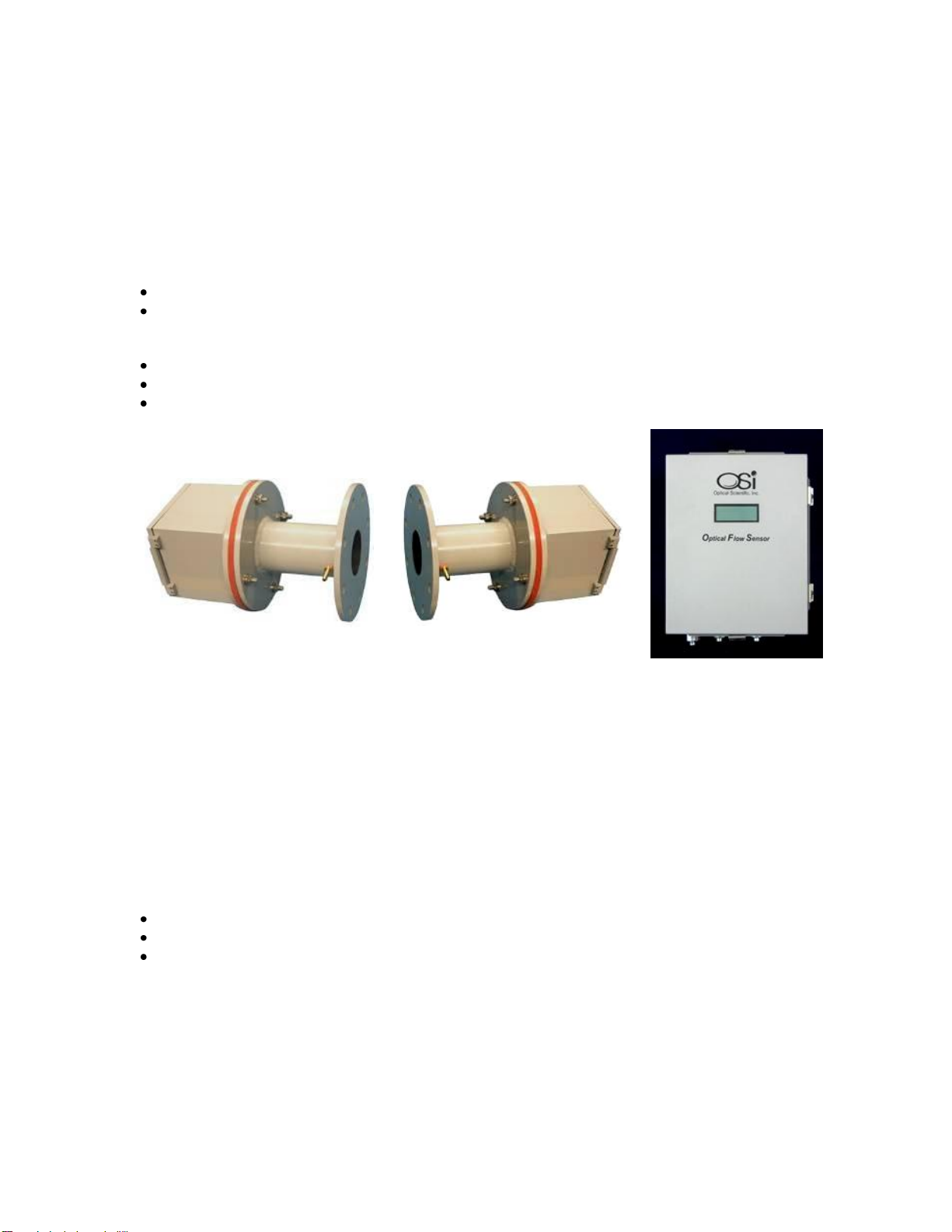
1.3 Description of Units............................................................................................................................... 4
1.3.1 OFS 2000CW Transmitter............................................................................................................... 5
1.4 OFS 2000CW Receiver (RX) Unit.......................................................................................................... 6
1.5 Control Box........................................................................................................................................... 7
1.6 Temperature Probe..............................................................................................................................10
1.7 Activator Heater ...................................................................................................................................10
2 Pre –Installation.........................................................................................................................................11
2.1 OFS Placement....................................................................................................................................11
2.2 OFS 2000CW Sensor Placement.........................................................................................................12
2.3 Flange Alignment Guidelines................................................................................................................13
2.4 Flange Mounting Examples..................................................................................................................14
2.5 Flange Pipe Extension..........................................................................................................................15
2.6 Flange Pipe Mounting ..........................................................................................................................16
3 Installation..................................................................................................................................................17
3.1 Required at Transmitter or Receiver Location.......................................................................................17
3.2 Required at Control Unit Location.........................................................................................................17
3.3 Mechanical...........................................................................................................................................18
3.3.1 TX/RX Units...................................................................................................................................18
3.3.2 Control Units..................................................................................................................................20
3.4 Purge Air..............................................................................................................................................21
3.5 OFS in Hazardous or High Temperature Applications...........................................................................23
3.6 Pressurization Air (Z-Purge Air)............................................................................................................24
3.6.1 Unit Tubing Instructions .................................................................................................................26
3.6.2 Pressurization Unit Set Up.............................................................................................................26
3.6.3 Pressurization Unit Operation.........................................................................................................27
3.7 AC Power Connections........................................................................................................................28
3.7.1 Transmitter Unit.............................................................................................................................28
3.7.2 Control Box....................................................................................................................................28
3.8 User Interface Connections..................................................................................................................29
3.9 OFS 200CW Interconnecting Cables....................................................................................................30
3.10 AGC Cable Connections for OFS 2000CW Models.............................................................................31
3.11 OFS Receiver Cable ..........................................................................................................................31
3.11.1 Temperature Probe Interconnect..................................................................................................32
3.11.2 Activator Heater Interconnect.......................................................................................................32
3.12 4-20 mA Current Loop Connections....................................................................................................33
3.13 TB2 Fault / Cal Relays & External Calibration.....................................................................................34
3.13.1 Fault Relay ..................................................................................................................................34
3.13.2 Cal Relay.....................................................................................................................................34
3.13.3 External Calibration Input.............................................................................................................34
3.14 Computer Connection.........................................................................................................................35
3.14.1 HyperTerminal Setup...................................................................................................................36
4 OFS System Configuration Setup ...............................................................................................................37
4.1 Checking Communications...................................................................................................................37
4.2 OFS 2000C Setup................................................................................................................................37
4.2.1 Units of Measurement....................................................................................................................37
4.2.2 Time Constant ...............................................................................................................................38
4.2.3 Serial Output..................................................................................................................................38
4.2.4 Current Loop..................................................................................................................................38
4.2.5 Correction Factor...........................................................................................................................39
4.2.6 Multiple Point Correction Factor.....................................................................................................40
4.2.7 Duct Area Data..............................................................................................................................41
4.2.8 Calibration Percentage (Optional) ..................................................................................................41
5 Poll Commands & Data Output...................................................................................................................42
5.1 "A" Poll (Short Data String) Output .......................................................................................................42

Optical Scientific Inc
OFS 2000CW User’s Guide
P/N 1910-905
Rev. 03/28/13
iii
5.1.1 "A" Poll Response Bytes................................................................................................................42
5.2 "C" Poll (Long Data String) Format.......................................................................................................43
5.2.1 “C” Poll Response Bytes ................................................................................................................43
5.2.2 Description of Status Indicator Codes (Bytes 29-32).......................................................................44
6 Transmitter and Receiver Setup..................................................................................................................45
6.1 Transmitter Setup.................................................................................................................................45
6.2 Receiver Setup.....................................................................................................................................46
7 Optical Alignment .......................................................................................................................................47
7.1.1 Avoiding Receiver Saturation.........................................................................................................50
8 Correlation..................................................................................................................................................51
9 Initial Check and Start-Up...........................................................................................................................52
9.1 Initial Check.........................................................................................................................................52
9.2 Visual Indicators...................................................................................................................................52
10 Maintenance.............................................................................................................................................54
10.1 Safety ................................................................................................................................................54
10.2 Preventive Maintenance.....................................................................................................................54
10.2.1 Window Cleaning Procedure........................................................................................................55
11 Troubleshooting........................................................................................................................................56
11.1 General Troubleshooting Guidelines...................................................................................................56
11.2 Control Enclosure Troubleshooting.....................................................................................................57
11.2.1 DSP lndicator LEDs.....................................................................................................................57
11.2.2 Control/Interface Indicators..........................................................................................................57
11.3 Transmitter Troubleshooting...............................................................................................................57
11.3.1 Transmitter "Power" Led Not Lit ...................................................................................................57
11.3.2 Transmitter "Signal" Led Not Lit....................................................................................................57
11.4 Receiver Troubleshooting...................................................................................................................57
11.4.1 Receiver "Power" Led Not Lit.......................................................................................................57
11.4.2 Receiver "Signal" Led Not Lit .......................................................................................................58
11.5 Error Messages..................................................................................................................................59
11.5.1 Fault (1) A and/or B Out of Range................................................................................................59
11.5.2 Warning (2) Velocity Out Of Range ..............................................................................................59
11.5.3 Fault (3) Input Voltage Out of Range............................................................................................59
11.5.4 Fault (5) Heating Activity Error......................................................................................................59
11.5.5 Fault (6) Temperature Probe Error ...............................................................................................59
11.5.6 Fault (7) Pressure Probe Error .....................................................................................................59
11.5.7 Warning (9) Clean Lens ...............................................................................................................59
12 Spare Parts ..............................................................................................................................................60
12.1 Recommended Spare Parts ...............................................................................................................60
12.2 Available Spare Parts.........................................................................................................................60
13 Technical Support.....................................................................................................................................61

Optical Scientific Inc
OFS 2000CW User’s Guide
P/N 1910-905
Rev. 03/28/13
iv
Table of Figures
Figure 1.1 OFS 2000CW Basic Components.................................................................................................. 1
Figure 1.2 OFS 2000CW System Components............................................................................................... 4
Figure 1.3 OFS 2000CW Transmitter.............................................................................................................. 5
Figure 1.4 OFS 2000CW Receiver.................................................................................................................. 6
Figure 1.5 OFS 2000CW Control Box............................................................................................................. 7
Figure 1.6 OFS Control Box............................................................................................................................ 8
Figure 1.7 Control Display .............................................................................................................................. 8
Figure 1.8 Pressure Sensor............................................................................................................................ 9
Figure 1.9 Temperature Probe.......................................................................................................................10
Figure 1.10 Activator Heater..........................................................................................................................10
Figure 1.11 Heater Current Sensor................................................................................................................10
Figure 2.1 OFS Placement ............................................................................................................................11
Figure 2.2 Typical Sensor Placement.............................................................................................................12
Figure 2.3 Flange Installation (cutaway).........................................................................................................13
Figure 2.4 Measured Flow Cross Section.......................................................................................................15
Figure 2.5 Flange Installation - Incorrect........................................................................................................16
Figure 2.6 Flange Installation - Correct..........................................................................................................16
Figure 2.7 Common Flange Dimensions........................................................................................................16
Figure 3.1 Common Vertical Installation.........................................................................................................18
Figure 3.2 Common Horizontal Installation.....................................................................................................18
Figure 3.3 OFS Mounting Hardware...............................................................................................................18
Figure 3.4 OFS TX/RX Overall Dimensions....................................................................................................19
Figure 3.5 Control Box Mounting Dimensions ................................................................................................20
Figure 3.6 Purge Air Detail.............................................................................................................................21
Figure 3.7 Rotameter (flow meter) .................................................................................................................21
Figure 3.8 "Natural" Air Purge........................................................................................................................21
Figure 3.9 Compressed Air Purge..................................................................................................................21
Figure 3.10 Purge Air at 90° to Vertical Flow..................................................................................................22
Figure 3.11 Rotameter Installation.................................................................................................................22
Figure 3.12 Typical Gate Valve Installation....................................................................................................23
Figure 3.13 Z-Purge Control Unit...................................................................................................................24
Figure 3.14 Control Unit Mounting Dimensions ..............................................................................................24
Figure 3.15 Typical Z-Purge Control Unit.......................................................................................................25
Figure 3.16 TX/RX Z-Purge Arrangement......................................................................................................25
Figure 3.17 Control Box Z-Purge Arrangement ..............................................................................................26
Figure 3.18 Transmitter AC Connections .......................................................................................................28
Figure 3.19 Control Box AC Connections.......................................................................................................28
Figure 3.20 User Analog Interface Connections.............................................................................................29
Figure 3.21 J5 Serial Port..............................................................................................................................29
Figure 3.22 OFS2000CW Interconnects........................................................................................................30
Figure 3.23 Receiver Cable Connections.......................................................................................................30
Figure 3.24 TX AGC Cable Connection..........................................................................................................31
Figure 3.25 RX AGC Cable Connection.........................................................................................................31
Figure 3.26 TB3 Connections........................................................................................................................33
Figure 3.27 Terminal Block 2.........................................................................................................................34
Figure 3.28 OFS 200CW Computer Connection.............................................................................................35
Figure 4.1 HyperTerminal Open.....................................................................................................................37
Figure 4.2 "V" Poll Output..............................................................................................................................37
Figure 4.3 Units of Measure...........................................................................................................................37
Figure 4.4 Setup: Time Constant ...................................................................................................................38
Figure 4.5 Serial Output.................................................................................................................................38
Figure 4.6 Current Loop 1..............................................................................................................................38
Figure 4.7 Current Loop Assignments............................................................................................................39
Figure 4.8 Correction Factor Entry.................................................................................................................39
Figure 4.9 Curve Fitting Setup.......................................................................................................................40
Figure 4.10 Curve Fitting Point Entry .............................................................................................................40

Optical Scientific Inc
OFS 2000CW User’s Guide
P/N 1910-905
Rev. 03/28/13
v
Figure 4.11 Curve Fitting Entry Check ...........................................................................................................40
Figure 4.12 Clearing Set Points.....................................................................................................................41
Figure 4.13 Duct Area....................................................................................................................................41
Figure 4.14 Calibration Percentage N/A.........................................................................................................41
Figure 6.1 OFS 2000CW TX Module..............................................................................................................45
Figure 6.2 OFS 2000CW RX Window............................................................................................................45
Figure 6.3 Centering Light Beam ...................................................................................................................45
Figure 6.4 TX Rear View................................................................................................................................45
Figure 6.5 Receiver "A" & "B" Lenses ............................................................................................................46
Figure 6.6 Receiver LEDs and Flow Direction................................................................................................46
Figure 7.1 Receiver Window "Cat’s Eyes" ......................................................................................................47
Figure 7.2 Transmitter Module.......................................................................................................................48
Figure 7.3 Beam Centering............................................................................................................................48
Figure 7.4 Front Panel Display (example).....................................................................................................48
Figure 7.5 Filter Material Insertion..................................................................................................................50
Figure 9.1 Transmitter LEDs..........................................................................................................................52
Figure 9.2 Receiver LEDs..............................................................................................................................52
Figure 9.3 Control Enclosure Display.............................................................................................................53
Figure 9.4 Control & DSP Indicator LED's......................................................................................................53
Figure 10.1 Window Cleaning........................................................................................................................55
Figure 11.1 DSP Indicators............................................................................................................................57
Figure 11.2 Control/Interface LEDs................................................................................................................57

Optical Scientific Inc
OFS 2000CW User’s Guide
P/N 1910-905
Rev. 03/28/13
vi
Caveats
Only trained personnel are allowed to service this equipment.
The OFS shall only be used in a manner specified by the manufacturer.
This equipment contains hazardous voltages.
Disconnect AC power before servicing.
Optical Scientific, Inc. will not be held liable for any accident, injury to
personnel, or damage to property incurred while operating or servicing this
equipment. Implementation and enforcement of proper work safety procedures
is solely the responsibility of the user, user employees or contracted personnel.
!CAUTION!
Read the entire User's Guide before proceeding with any
installation or maintenance activity.

Optical Scientific Inc
OFS 2000CW User’s Guide
P/N 1910-905
Rev. 03/28/13
1
1 OFS -2000CW OVERVIEW
1.1 Theory of Operation
Scintillation is the variation of light caused by it’s passage through pockets of air with different temperature and
density. It’s what makes the stars seem to twinkle in the night sky. OFS uses scintillation in air flow to
determine velocity. Our proven measurement technology, originally developed and patented for use in
atmospheric visibility and turbulence detecting instruments, offers unequalled response and accuracy in air
flow sensing.
This measurement is not affected by temperature and pressure.
It is completely non-intrusive to the air flow.
The basic system consists of:
Transmitter a stand-alone unit that emits an eye-safe red light beam
Receiver unit containing 2 photodetectors and signal amplifiers
Control unit that houses the DC power supply, DSP, control and user interface
Transmitter
Receiver
Control Unit
Figure 1.1 OFS 2000CW Basic Components
The LED in the transmitter emits a light beam which illuminates twin photodetectors in the receiver.
The received signal is amplified and sent to the Digital Signal Processor (DSP) in the Control Unit. The results
are shown on the front panel display and relayed to the customer either through a 4-20 mA current loop or
through an RS-232 interface.
The system is designed to fit standard commercial/industrial installations and to easily interface with PC, PLC,
DAS, CEM - almost any data collection device
The OFS -2000CW is a valuable tool for:
Environmental Monitoring (factory and power plant stacks, refinery flare stacks)
Process control. (gas transfer, boiler and incinerator efficiency)
Local airflow monitoring (exhaust vents, wind tunnels)
Environmental Monitoring
Process Control
Local Airflow Monitoring
Emissions-regulated industries
can use this information to
calculate volumetric flow from
their smokestacks. OFS is EPA -
compliant.
The OFS can measure the speed
of the air or gas flow in an
industrial process. The data can
be integrated into the monitoring
and control system.
OFS has been used to measure
airflow in underground tunnel
vents, roof exhaust vents, wind
tunnels and other applications

Optical Scientific Inc
OFS 2000CW User’s Guide
P/N 1910-905
Rev. 03/28/13
2

Optical Scientific Inc
OFS 2000CW User’s Guide
P/N 1910-905
Rev. 03/28/13
3
1.2 OFS -2000CW Specifications
Flow Performance
Technique
Optical scintillation
Velocity Range
1.0 to 40 m/s velocity
Path Distance
2 to 10+ meters (6 to 30+ feet)
Accuracy
2% of reading
Resolution
0.1 m/s
Averaging Time
User selectable: 3 sec to 600 sec
Long Term Drift
<1% >6 months
Media Temperature
No upper limit (for cold air applications an ‘activator’ may be required)
Light Source
670 nm red LED
Beam Divergence
5 degrees
Optics
Quartz
Purge
Purge fittings supplied
(Nominal recommendation is
4 CFM per system)
Factory-supplied instrument –grade purged air with
1-2 CFM
Maintenance
Diagnostics
Continuous monitoring of sensor status including power supply voltage
check, performance check, optics contamination, etc
Indicators
TX Optical Unit - LEDs indicating power ON & correct operation
RX Optical Unit - LEDs indicating power ON & correct operation
Control Box - LEDs indicating correct operation
Operational Environment
Ambient Temperature
-40 to 60 C
Dust Intrusion
IP65
Moisture
0-100% condensing with dry purge air supplied
Data Output
Four 4-20 mA optical isolated outputs
Loop 1 –Velocity
Loop 3 –Temperature (optional)
Loop 2 - Volume
Loop 4 –Pressure (optional)
Two relays for fault and calibration check indications
Control/Data Interface
RS-232 ASCII, DB9 exterior serial port. USB adapter included
Baud rate (9600 standard) 8 data bits, no parity, 1 stop bit
2 Data output string formats
Short with only velocity and P/F status
Long with all velocity and status data
Front panel backlit LED display
Power Requirements
Fuse, Surge, & EMI protected
Transmitter Unit
Universal 100-240 VAC, 50/60 Hz, 12 VA
Control Box
Universal 100-240 VAC, 50/60 Hz, 40 VA
Activator Heater
120 VAC, 50/60 Hz, 15A
Physical Characteristics
Weight
TX & RX Optical Units
5 kg ea
Control Box (NEMA-4),
4.7 kg
Flange Adapter (spool piece) (2)
3 kg ea
Dimensions
TX & RX Optical Units
15 x 15 x 14 cm ea
Control Box (NEMA-4),
34 x 28 x 17 cm
Flanged Adapter (spool piece)
9-in. dia. (150# 4” ANSI bolt pattern on user
end)
6-inch (15 cm) long
Materials
TX & RX Optical Units
Aluminum with powder-coat paint
Control Box
Aluminum with powder-coat paint (NEMA-4)
Adapter
Aluminum with powder-coat paint

Optical Scientific Inc
OFS 2000CW User’s Guide
P/N 1910-905
Rev. 03/28/13
4
1.3 Description of Units
The OFS -2000CW models has five main elements:
Transmitter (TX) Unit [1910-100-1]
Receiver (RX) Unit [1910-200]
Control Box [1910-302-1]
Activator Heater [1910-850]
Temperature Probe [1910-852]
The TX and RX Units use identical packaging to house the optical and electronic subsystems. All parts are
made from powder-coated aluminum, and are weather tight. Both housings have holes for standard 1/2”
electrical fittings for cable or conduit. 1/4” NPT fittings are provided for low-pressure air if internal
pressurization is required.
Note: Both TX and RX units are supplied with integral “spool piece” flange adapters. These adapters provide
isolation and are equipped with 1/8” NPT purge air fittings to keep the light path clear.
The Control Box houses the DSP processor, power supply, and interface components. The Box is connected
to the RX Unit via a shielded cable (P/N 1910-217) supplied with the OFS. The Control Box meets NEMA-4
standards. It has 1/2” conduit holes for the user to make power and signal/communications connections. The
user supplies power and communication cables. The use of 1/2-inch flex conduit is recommended to protect
the wiring from the harsh industrial environment.
The Temperature Probe is used to monitor flow temperature.
The Activator Heater is used to excite scintillation where air flow is < 150°F [65.6°C]
Figure 1.2 OFS 2000CW System Components

Optical Scientific Inc
OFS 2000CW User’s Guide
P/N 1910-905
Rev. 03/28/13
5
1.3.1 OFS 2000CW Transmitter
The OFS 2000CW TX Unit, P/N 1910-100-1, consists of two major parts, the housing and the flange adapter.
Figure 1.3 illustrates the major components of the OFS 2000CW TX Unit.
The OFS TX and RX units (with integral spool piece) are designed to mate to an ANSI 150 # 4” flange as is
commonly used in commercial applications. The flange adapter (spool piece) is provided for this purpose. It
also provides thermal isolation from the air flow to be measured and, when supplied with purge air, an air
curtain to help keep the atmosphere in the mounting nozzles clear and the windows clean.
The transmitter housing contains the transmitter optical assembly and transmitter driver circuit board. The
optical assembly is pre-aligned in the factory and needs no focusing, just aiming. The LED (transmitter optical
module) aim is adjustable to ensure the eye-safe red light beam properly illuminates the detectors in the RX
Unit.
The transmitter driver circuit board contains a universal (100 - 240 VAC) power supply, 1A, 250V, 3AG fuse,
and modulation & drive circuitry for the light source.
Two indicator LEDs are provided on the PCB to indicate correct operation of the TX Unit:
a red LED is ON when AC power is supplied.
a green LED is ON when the transmitter red LED is operating with the proper modulation.
A user-supplied AC power cable connects to the three position terminal block on the PCB. [See Section 3.7
“AC Power Connections”]
Figure 1.3 OFS 2000CW Transmitter

Optical Scientific Inc
OFS 2000CW User’s Guide
P/N 1910-905
Rev. 03/28/13
6
1.4 OFS 2000CW Receiver (RX) Unit
The RX Unit, P/N 1910-200 is equipped at the factory with an interconnecting cable for the AGC option.
The Receiver consists of two major parts, the housing and the flange adapter (spool piece). Figure 1.4
illustrates the major components of the RX unit.
The OFS TX and RX units (with integral spool piece) are designed to mate to a 150#, 4” ANSI flange as is
commonly used in commercial applications. The flange adapter (spool piece) is provided for this purpose. It
also provides thermal isolation from the air flow to be measured and, when supplied with purge air, an air
curtain to help keep the atmosphere in the mounting nozzles clear and the windows clean.
Mounting screws and gaskets are supplied for installing the Transmitter and flange adapter on the customer’s
flange. A silicone gasket is provided between the housing and the flange adapter to provide a weather-tight
seal. A 9-inch diameter Kevlar gasket is provided for the user to place between the flange adapter and the
user supplied mating flange. Complete sealing of the flange is critical for proper operation.
The housing contains the receiver optics and amplifier electronics subassemblies. The optics assembly is pre-
aligned in the factory and needs no focusing in the field. The optical assembly is mounted on a circular PCB
which is rotated to align the twin photodetectors with the direction of flow.
Two indicator LEDs are provided on the PCB to indicate correct operation of the TX Unit:
A red LED is ON when AC power is supplied.
A green LED is ON when light is being received from the TX Unit.
(Note: This LED is NOT an indicator of signal strength.
Figure 1.4 OFS 2000CW Receiver

Optical Scientific Inc
OFS 2000CW User’s Guide
P/N 1910-905
Rev. 03/28/13
7
1.5 Control Box
1910-302-1 Control Box is housed in an enclosure that meets NEMA-4 standards The Control Box may be
hard-wired using either cables or flexible conduit at the customer’s discretion.
A
AC Power connection J1
B
Power Supply
The OFS contains a universal input DC power supply that operates with input voltages from 100 to
240 VAC, 50/60 Hz. This allows the unit to operate with all line voltages world-wide.
C
Control/Interface Board
Central point for all of the OFS interconnections.
DC Power distribution for internal components and OFS Receiver
TB1 connections for the Control Box to the RX Unit. [F]
TB2 connections for the fault relays, and optional Calibration [E]
TB3 connections for 4-20 mA current loops.[D]
J2, J3, J4 DSP data interconnects
J5 DB9 Serial Data I/O (connects to enclosure bottom [J5])
J6 connections for enclosure cover display [L]
J7 Remote display connector (connects to enclosure bottom [J7])
J8 Factory test connector
J9 Air Temperature connects to enclosure bottom [J9]
J10 Heater Current Sensor connects to enclosure bottom [J10]
U6 Pressure Sensor connects to filter fitting “Pressure Port” at enclosure bottom
D
TB3 4-20mA Current Loop Outputs [See Sections 3.12 and Section 4.2.4]
E
TB2 Fault Relay, Cal Relay & External Cal Check [See Section 3.13]
Figure 1.5 OFS 2000CW Control Box

Optical Scientific Inc
OFS 2000CW User’s Guide
P/N 1910-905
Rev. 03/28/13
8
F
TB1 Receiver Power and Signal I/O
G
Digital Signal Processor (DSP)
This board is a state-of-the-art digital processor used to convert the optical data from the RX Unit
into flow measurements. This data is transmitted to the microcontroller to be integrated into the
information data stream.
H
1/2” Conduit fitting for User’s Analog I/O wiring
I
1/2” Conduit fitting for receiver interconnect cabling
J
Control unit information display
K
Ground Lug –User must connect to Earth ground.
L
J5 DB9 RS-232 serial interface connector [connects to J5 header on Control Interface PCB]
M
J7 Remote display connector [connects to J7 header on Control Interface PCB]
N
J9 Air Temp. sensor connector [connects to J9 header on Control Interface PCB]
O
J10 Heater current sensor connector [connects to J10 header on Control Interface PCB]
P
Filter fitting for air pressure sensor [connects to U6 pressure sensor on Control Interface PCB]
Figure 1.6 OFS Control Box
The Control Box Display is a back lit LCD
type and shows:
Velocity
Volumetric Flow
Temperature of flow media
Atmospheric pressure
Signal correlation
A Channel & B Channel voltages
Figure 1.7 Control Display

Optical Scientific Inc
OFS 2000CW User’s Guide
P/N 1910-905
Rev. 03/28/13
9
The Pressure Sensor is located on the
Control/Interface board. It is a state-of-the-art,
monolithic, signal conditioned, silicon piezo-resistive
pressure sensor. It connects to a filter fitting at the
bottom of the control enclosure. See Figure 1.8.
This sensor provides an accurate, high level analog
output signal that is proportional to applied pressure.
The pressure range is rated 2.2 - 16.7 PSI.
The pressure sensor output is integrated into the data
stream and passed on to the DSP along with
information from the Temperature Sensor.
Figure 1.8 Pressure Sensor

Optical Scientific Inc
OFS 2000CW User’s Guide
P/N 1910-905
Rev. 03/28/13
10
1.6 Temperature Probe
The Temperature Probe [1910-852] is an RTD type. The probe itself is 1/4” diameter 18” long, stainless steel,
with an aluminum connector head. It screws into a 1/2” NPT port and is provided with a cable which plugs into
the J3 connector at the bottom of the Control Box. The operational range for OFS 2000CW is -40° to +932°F [-
40° to +500°C].
1.7 Activator Heater
Figure 1.9 Temperature Probe
1.1
Figure 1.10 Activator Heater
The Activator Heater [1910-850] is rated at 1500W @ 120V. It
is recommended that a dedicated branch circuit controlled with
a 15A breaker be provided. The heater element is 3/4” in
diameter 36” long with an INCONEL sheath and threaded to
fit a 3/4” NPT port. The active portion of the heating element
begins 12” from the base and extends the remaining 24” to the
end of the rod. The connector head is Class I, Div. 1 & 2,
Groups C,D rated. The heater element is equipped with a K-
type thermocouple. For OFS 2000CW application a current-
sensing circuit is used. The connecting cable (provided) plugs
into the J4 connector at the bottom of the Control Box.
Figure 1.11 Heater Current Sensor
!CAUTION!
Heater can reach temperatures of over 14000°F [7760°C] when
unregulated. Do not operate without proper control.

Optical Scientific Inc
OFS 2000CW User’s Guide
P/N 1910-905
Rev. 03/28/13
11
2 Pre –Installation
2.1 OFS Placement
Since air flow has the characteristics of a fluid, the best location for any flow sensor is always at the place
where the flow profile is well developed and consistent. A certain amount of leading and trailing distance
(usually defined in “pipe diameters”) from bends or flow disturbances in the pipe or stack is necessary for
stabilization. Most types of flow sensors need very long straight distances to achieve a steady near-laminar
flow. The common sensor sees turbulence as an error which needs to be eliminated. For OFS, turbulence is
desirable. It is always easier to add turbulence than to eliminate it . Because the OFS light beam passes
through the entire flow cross-section, it can tolerate much shorter linear length, where other instruments may
require ten times the distance or more before they can become effective.
Usually linear lengths more than two
times the pipe diameter leading
(upstream of the OFS) and one times the
pipe diameter trailing are good enough
for OFS to make a representative flow
measurement. In some cases, OFS 2000
units have been installed right at the
elbow of a pipe and still provided
satisfactory measurements. Consult OSI
if you have any placement concerns.
Application requirements may require
differing arrangements from the standard
stack or duct. The shape, diameter, or
cross section must also be taken into
consideration. In some cases two OFS
systems have been used in an “X”
configuration to measure a large stack.
In others, they have been mounted
diagonally to measure across a
rectangular duct corner-to-corner. The
OFS will measure at any distance from
0.15 to 10 meters. Other distances are
possible. Again consult OSI if you have
questions regarding proper placement.
Note: In cases like these, it is advisable
to mount the units so that the light beam
is aligned along the axis of the upstream
bend. This ensures that any stratification
in the developed flow pattern will pass
through the light beam and not slip by on
either side.
The Transmitter should be placed on the
inside curve of the upstream bend
Figure 2.1 OFS Placement

Optical Scientific Inc
OFS 2000CW User’s Guide
P/N 1910-905
Rev. 03/28/13
12
2.2 OFS 2000CW Sensor Placement
In addition to the general placement considerations described in the previous section, proper allowance must
be made for the location of the Temperature Probe [1910-852] and Activator Heater [1910-850].
These are placed upstream of the light beam axis as shown in Figure 2.2 below. The heater and temperature
probe are aligned on the centerline and installed on the receiver side of the duct. The heater should be
mounted 8” upstream from the TX/RX light beam axis, and the temperature probe should be mounted 24 “
upstream from the heater. A certain amount of shifting may be allowed for as not all sites are ideal, but the
critical parameter is the 8” centerline distance between the heater and the light path. This should be adhered
to at minimum.
Figure 2.2 shows a typical installation in a horizontal duct.
Figure 2.2 Typical Sensor Placement
Component Description
Transmitter (not shown)
Mounted on opposite side and centered on common axis with receiver
1
Receiver Unit [1910-200]
Centered on axis with transmitter (see Flange Alignment in Section 2)
2
Control Unit [1910-302-1]
Contains DSP/Sensor and Customer Interfaces, Display
3
Activator Heater [1910-850]
Mounts in 3/4” NPT fitting at least 8” upstream on center with RX
4
Temp Probe [1910-852]
Mounts in 1/2” NPT fitting at least 24” upstream from heater
5
Heater AC Supply
Dedicated AC Line

Optical Scientific Inc
OFS 2000CW User’s Guide
P/N 1910-905
Rev. 03/28/13
13
OFS
Transmitter
OFS Flange Adapter
Customer Mounting
Flange
Stack
Wall
2.3 Flange Alignment Guidelines
The OFS 2000CW is designed to function in difficult industrial environments and will operate satisfactorily in
adverse conditions. It can operate over a broad range of media opacity with little or no change in accuracy.
However, these advantages can be completely negated if the transmitter and receiver cannot be aligned
properly –meaning that the receiver cannot “see” the light beam from the transmitter sufficiently well for proper
response.
The first step to getting the most out of your sensor is making sure the mounting flanges are aligned properly.
The OFS 2000CW is designed to mount to common ANSI 150# 4“ pipe flanges. These flanges must be
installed:
diametrically opposite each other
on a level horizontal plane
squarely aligned on the same axis
Proper care in mounting the flanges to the stack will
pay off many times over.
There is no need to measure and know the path length
for an OFS meter, which is required (for example) when
mounting an opacity meter. Therefore, in this regard,
mounting an OFS is simpler.
Alignment need not be micrometrically precise, but it
must be done so that the axis of the transmitter and the receiver are aligned on the same centerline. The
method of determining placement and alignment of the mounting flanges is the responsibility of the customer
personnel or contracted service technicians.
Careful “eyeball” reference should suffice, but use of spirit levels, laser pointers, and other such alignment
tools is recommended. Sensible precautions and attention to detail should be all that is required to complete
the job properly.
We recommend that the user study:
OFS 2000 User’s Guide “Installation Considerations”
OSI Brochure “OFS Placement Advantage”
A typical basic installation is shown here
at right. The OFS Transmitter and
Receiver are supplied with flange
adapters to mate to the customer’s
mounting flange. The customer’s flange is
typically cemented or welded in place.
The inner end may be flush with the wall,
or protrude depending on customer
needs. [See Section 2.5 “Flange Pipe
Extension”]
Figure 2.3 Flange Installation (cutaway)
This manual suits for next models
1
Table of contents
Other OSI Accessories manuals
Popular Accessories manuals by other brands

Aqara
Aqara Water Leak Sensor quick start guide

ASM
ASM posirot PRAS Series Installation and operation manual

USC
USC Tube Series 3500 Operator's manual

Blyss
Blyss 21217KF Safety guide

Edu-Logger
Edu-Logger 900-209 Guide

Venture Measurement
Venture Measurement Genuine Bindicator VRF-2000 Series quick start guide