OSI OFS-2000FW User manual

Optical Scientific Inc
OFS 2000FW User’s Guide
P/N 1910-901-1
User's Guide
OFS -2000FW
Optical Flow Sensor
03/28/13
OPTICAL SCIENTIFIC INC
Tel: +1-301-963-3630
Fax: +1-301-948-4674
2 Metropolitan Ct, Suite 6
Gaithersburg, MD 20878 USA
www.opticalscientific.com

Optical Scientific Inc
OFS 2000FW User’s Guide
P/N 1910-901-1
Rev. 03/28/13
i
Revision Log
Rev Date
Description of Changes
3/23/2004
Production Release
3/24/2005
Change on pages 3, 14 and 27
6/8/05
Change the interface board from single current loop to dual current loops.
10/9/06
Release Model 2000W with Automatic Transmitter Power Feedback Control
5/11/07
Add Installation Procedure Summary in Appendix B.
7/1/07
Change new address
08/04/10
Update OFS 2000W Wiring Diagram in Appendix A p39
03/28/2013
Re-written & re-organized to include –FW model, Thermal Activator, enhanced Purge
and Z-Purge sections, updated procedures and specifications.
OFS-2000 Certifications
UL 3101-1:1993
CSA C22.2 No. 1010.1:92
IEC 61010:1999
OSi is an ISO-9001 Registered Company

Optical Scientific Inc
OFS 2000FW User’s Guide
P/N 1910-901-1
Rev. 03/28/13
ii
Table of Contents
1 OFS -2000FW OVERVIEW.......................................................................................................................... 1
1.1 Theory of Operation .............................................................................................................................. 1
1.2 OFS -2000FW Specifications ................................................................................................................ 2
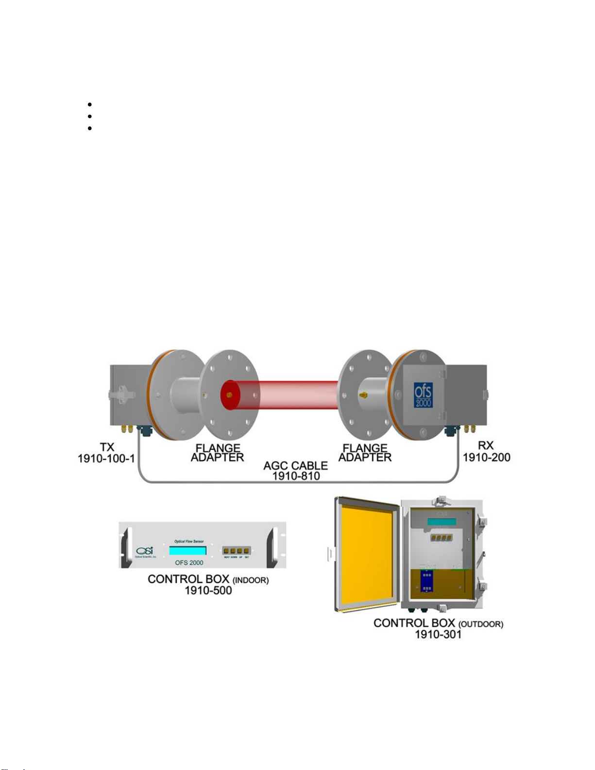
1.3 Description of Units............................................................................................................................... 3
1.4 Transmitter (TX) Unit............................................................................................................................. 4
1.5 OFS 2000FW Receiver (RX) Unit.......................................................................................................... 5
1.6 Control Box(es) Indoor And Outdoor...................................................................................................... 6
1.6.1 Outdoor Control Box ....................................................................................................................... 6
1.6.2 Indoor Control Box.......................................................................................................................... 7
2 Pre –Installation.......................................................................................................................................... 8
2.1 OFS Placement..................................................................................................................................... 8
2.2 Flange Alignment Guidelines................................................................................................................. 9
2.3 Flange Mounting Examples..................................................................................................................10
2.4 Flange Pipe Extension..........................................................................................................................11
2.5 Flange Pipe Mounting ..........................................................................................................................12
3 Installation..................................................................................................................................................13
3.1 Required at Transmitter or Receiver Location.......................................................................................13
3.2 Required at Control Unit Location.........................................................................................................13
3.3 Mechanical...........................................................................................................................................14
3.3.1 TX/RX Units...................................................................................................................................14
3.3.2 Control Units..................................................................................................................................16
3.4 Purge Air..............................................................................................................................................17
3.5 OFS in Hazardous or High Temperature Applications...........................................................................19
3.6 Pressurization Air (Z-Purge Air)............................................................................................................20
3.6.1 Unit Tubing Instructions .................................................................................................................22
3.6.2 Pressurization Unit Set Up.............................................................................................................22
3.6.3 Pressurization Unit Operation.........................................................................................................23
3.7 AC Power Connections........................................................................................................................24
3.7.1 Transmitter Unit.............................................................................................................................24
3.7.2 Control Boxes................................................................................................................................24
3.8 User Interface Connections..................................................................................................................25
3.9 OFS 2000FW Interconnecting Cables...................................................................................................26
3.10 AGC Cable Connections for OFS 2000FW Models.............................................................................27
3.11 OFS Receiver Cable ..........................................................................................................................27
3.12 4-20 mA Current Loop And Relay Connections...................................................................................28
3.13 RS-232 Connections..........................................................................................................................29
3.13.1 Limited Distance Modem (LDM) Connections...............................................................................29
3.13.2 Fiber Optic Modem (FOM) Connections.......................................................................................30
3.14 Computer Connection.........................................................................................................................31
4 Poll Commands & Data Output...................................................................................................................32
4.1 "A" Poll (Short Data String) Output .......................................................................................................32
4.1.1 "A" Poll Response Bytes................................................................................................................32
4.2 "C" Poll (Long Data String) Format.......................................................................................................32
4.2.1 “C” Poll Response Bytes ................................................................................................................33
4.2.2 Description of Status Indicator Codes (Bytes 29-32).......................................................................34
4.3 Reading The Output Data.....................................................................................................................35
5 Data Collection...........................................................................................................................................36
5.1 Using “C” Poll.......................................................................................................................................37
5.2 Using Continuous Polling .....................................................................................................................37
6 Optical Alignment .......................................................................................................................................38
6.1 Receiver Setup.....................................................................................................................................38
6.2 Transmitter Setup.................................................................................................................................39
6.2.1 Transmitter Aiming Considerations.................................................................................................40
6.2.2 Avoiding Receiver Saturation.........................................................................................................42
7 Correlation..................................................................................................................................................43
8 Initial Check and Start-Up...........................................................................................................................44
8.1 Initial Check.........................................................................................................................................44

Optical Scientific Inc
OFS 2000FW User’s Guide
P/N 1910-901-1
Rev. 03/28/13
iii
8.1.1 Visual Indicators ............................................................................................................................44
8.2 OFS Start-Up.......................................................................................................................................45
8.2.1 OFS Initial Display Sequence.........................................................................................................46
8.2.2 Display and Keypad.......................................................................................................................47
8.2.3 Check Firmware Version Procedure...............................................................................................49
8.2.4 Correction Factor...........................................................................................................................50
8.2.5 Curve Fitting..................................................................................................................................50
8.2.6 Calibration Verification...................................................................................................................51
8.3 External Calibration (RATA) .................................................................................................................52
9 Maintenance...............................................................................................................................................53
9.1 Safety ..................................................................................................................................................53
9.2 Preventive Maintenance.......................................................................................................................53
9.2.1 Window Cleaning Procedure..........................................................................................................54
10 Troubleshooting........................................................................................................................................55
10.1 General Troubleshooting Guidelines...................................................................................................56
10.2 Power and Signal Checks...................................................................................................................57
10.2.1 DSP Power and Signal.................................................................................................................57
10.2.2 Transmitter "Power" Led Not Lit ...................................................................................................57
10.2.3 Transmitter "Signal" Led Not Lit....................................................................................................57
10.2.4 Receiver "Power" Led Not Lit .......................................................................................................57
10.2.5 Receiver "Signal" Led Not Lit .......................................................................................................57
10.2.6 Signal Voltage Checks - Receiver................................................................................................58
10.2.7 Signal Voltage Checks –Receiver/Control Unit............................................................................58
10.3 Control Box Troubleshooting ..............................................................................................................59
10.4 Error Messages..................................................................................................................................59
10.4.1 Channel A/B Out of Range...........................................................................................................59
10.4.2 DSP Timeout ...............................................................................................................................59
11 Spare Parts ..............................................................................................................................................60
11.1 Recommended Spare Parts ...............................................................................................................60
11.2 Available Spare Parts.........................................................................................................................60
12 Appendix A OFS 2000 Thermal Activator..................................................................................................61
12.1 OVERVIEW........................................................................................................................................61
12.1.1 Theory of Operation.....................................................................................................................61
12.2 General Heater Specifications............................................................................................................62
12.3 Thermal Activator Wiring ....................................................................................................................63
12.4 Description of Units............................................................................................................................64
12.5 Thermal Activator...............................................................................................................................65
13 Pre –Installation.......................................................................................................................................66
13.1 Thermal Activator Placement..............................................................................................................66
14 Installation................................................................................................................................................67
15 Appendix B OFS Curve Fitting Procedure.................................................................................................68
15.1 Introduction........................................................................................................................................68
15.2 Equipment Setup................................................................................................................................69
15.2.1 OFS and Computer Setup............................................................................................................69
15.2.2 Curve Fitting Procedure ...............................................................................................................69
15.3 Curve Fitting Data Entry.....................................................................................................................70
15.4 Curve Fitting Verification.....................................................................................................................71
16 Technical Support.....................................................................................................................................72
16.1 Before Calling Technical Support:.......................................................................................................72

Optical Scientific Inc
OFS 2000FW User’s Guide
P/N 1910-901-1
Rev. 03/28/13
iv
Table of Figures
Figure 1.1 OFS Basic Components................................................................................................................. 1
Figure 1.2 OFS 2000FW System Components................................................................................................ 3
Figure 1.3 OFS 2000FW Transmitter.............................................................................................................. 4
Figure 1.4 OFS 2000FW Receiver.................................................................................................................. 5
Figure 1.5 OFS Control Box (Outdoor)............................................................................................................ 6
Figure 1.6 Control Box Interior........................................................................................................................ 7
Figure 1.7 Control Box Front Panel................................................................................................................. 7
Figure 1.8 Control Box Rear Panel ................................................................................................................. 7
Figure 1.9 Interface Board.............................................................................................................................. 7
Figure 2.1 OFS Placement ............................................................................................................................. 8
Figure 2.2 Flange Installation (cutaway).......................................................................................................... 9
Figure 2.3 Measured Flow Cross Section.......................................................................................................11
Figure 2.4 Flange Installation - Incorrect........................................................................................................12
Figure 2.5 Flange Installation - Correct..........................................................................................................12
Figure 2.6 Common Flange Dimensions........................................................................................................12
Figure 3.1 Common Vertical Installation.........................................................................................................14
Figure 3.2 Common Horizontal Installation.....................................................................................................14
Figure 3.3 OFS Mounting Hardware...............................................................................................................14
Figure 3.4 OFS TX/RX Overall Dimensions....................................................................................................15
Figure 3.5 Outdoor Control Box Mounting Dimensions...................................................................................16
Figure 3.6 OFS 19” Rack Mountable Control Box...........................................................................................16
Figure 3.7 Purge Air Detail.............................................................................................................................17
Figure 3.8 Rotameter (flow meter) .................................................................................................................17
Figure 3.9 "Natural" Air Purge........................................................................................................................17
Figure 3.10 Compressed Air Purge................................................................................................................17
Figure 3.11 Purge Air at 90° to Vertical Flow..................................................................................................18
Figure 3.12 Rotameter Installation.................................................................................................................18
Figure 3.13 Typical Gate Valve Installation ....................................................................................................19
Figure 3.14 Z-Purge Control Unit...................................................................................................................20
Figure 3.15 Control Unit Mounting Dimensions ..............................................................................................20
Figure 3.16 Typical Z-Purge Control Unit.......................................................................................................21
Figure 3.17 TX/RX Z-Purge Arrangement......................................................................................................21
Figure 3.18 Control Box Z-Purge Arrangement ..............................................................................................22
Figure 3.19 Transmitter AC Connections .......................................................................................................24
Figure 3.20 Control Box AC Connections.......................................................................................................24
Figure 3.21 User Interface Connections.........................................................................................................25
Figure 3.22 OFS2000FW Interconnects........................................................................................................26
Figure 3.23 Receiver Cable Connections.......................................................................................................26
Figure 3.24 TX AGC Cable Connection..........................................................................................................27
Figure 3.25 RX AGC Cable Connection.........................................................................................................27
Figure 3.26 TB3 Connections........................................................................................................................28
Figure 3.27 LDM Connection.........................................................................................................................29
Figure 3.28 Fiber Optic Modem Connection...................................................................................................30
Figure 4.1 Data Fields and Bytes...................................................................................................................35
Figure 4.2 Status Codes................................................................................................................................35
Figure 5.1 Connect PC to Controller ..............................................................................................................36
Figure 5.2 HyperTerminal setup steps ...........................................................................................................36
Figure 5.3 HyperTerminal Data Display..........................................................................................................37
Figure 6.1 Receiver "A" & "B" Lenses ............................................................................................................38
Figure 6.2 Receiver LEDs and Flow Direction................................................................................................38
Figure 6.3 OFS 2000FW TX Module..............................................................................................................39
Figure 6.4 OFS 2000FW RX Window.............................................................................................................39
Figure 6.5 Centering Light Beam ...................................................................................................................39
Figure 6.6 TX Rear View................................................................................................................................39
Figure 6.7 Receiver Window "Cat’s Eyes"......................................................................................................40
Figure 6.8 Transmitter Module.......................................................................................................................41

Optical Scientific Inc
OFS 2000FW User’s Guide
P/N 1910-901-1
Rev. 03/28/13
v
Figure 6.9 Beam Centering............................................................................................................................41
Figure 6.10 Front Panel Display (example) ...................................................................................................41
Figure 6.11 Filter Material Insertion................................................................................................................42
Figure 8.1 Transmitter LEDs..........................................................................................................................44
Figure 8.2 Receiver LEDs..............................................................................................................................44
Figure 8.3 DSP Power LEDs..........................................................................................................................44
Figure 8.4 Correction Factor Display..............................................................................................................50
Figure 9.1 Window Cleaning..........................................................................................................................54
Figure 10.1 DSP Power Indicators.................................................................................................................57
Figure 10.2 DSP “Main Com ..........................................................................................................................57
Figure 12.1 Typical Thermal Activator Setup..................................................................................................61
Figure 12.2 Thermal Activator Dimensions.....................................................................................................62
Figure 12.3 Heater Wiring..............................................................................................................................63
Figure 12.4 Heater Schematic .......................................................................................................................63
Figure 12.5 OFS 2000FW and Thermal Activator Components......................................................................64
Figure 12.6 Thermal Activator........................................................................................................................65
Figure 12.7 Heater Thermocouple .................................................................................................................65
Figure 13.1 Typical Thermal Activator Setup..................................................................................................66

Optical Scientific Inc
OFS 2000FW User’s Guide
P/N 1910-901-1
Rev. 03/28/13
vi
Caveats
Only trained personnel are allowed to service this equipment.
The OFS shall only be used in a manner specified by the manufacturer.
This equipment contains hazardous voltages.
Disconnect AC power before servicing.
Optical Scientific, Inc. will not be held liable for any accident, injury to
personnel, or damage to property incurred while operating or servicing this
equipment. Implementation and enforcement of proper work safety procedures
is solely the responsibility of the user, user employees or contracted personnel.
!CAUTION!
Read the entire User's Guide before proceeding with any
installation or maintenance activity.

Optical Scientific Inc
OFS 2000FW User’s Guide
P/N 1910-901-1
Rev. 03/28/13
1
1 OFS -2000FW OVERVIEW
1.1 Theory of Operation
Scintillation is the variation of light caused by it’s passage through pockets of air with different temperature and
density. It’s what makes the stars seem to twinkle in the night sky. OFS uses scintillation in air flow to
determine velocity. Our proven measurement technology, originally developed and patented for use in
atmospheric visibility and turbulence detecting instruments, offers unequalled response and accuracy in air
flow sensing.
This measurement is not affected by temperature and pressure.
It is completely non-intrusive to the air flow.
The basic system consists of:
Transmitter a stand-alone unit that emits an eye-safe red light beam
Receiver unit containing 2 photodetectors and signal amplifiers
Control unit that houses the DC power supply, DSP, control and user interface
Transmitter
Receiver
Control Unit
(indoor or outdoor)
Figure 1.1 OFS Basic Components
The LED in the transmitter emits a light beam which illuminates twin photodetectors in the receiver.
The received signal is amplified and sent to the Digital Signal Processor (DSP) in the Control Unit. The results
are shown on the front panel display and relayed to the customer either through a 4-20 mA current loop or
through an RS-232 interface.
The system is designed to fit standard commercial/industrial installations and to easily interface with PC, PLC,
DAS, CEM - almost any data collection device
The OFS -2000FW is a valuable tool for:
Environmental Monitoring (factory and power plant stacks, refinery flare stacks)
Process control. (gas transfer, boiler and incinerator efficiency)
Local airflow monitoring (exhaust vents, wind tunnels)
Environmental Monitoring
Process Control
Local Airflow Monitoring
Emissions-regulated industries
can use this information to
calculate volumetric flow from
their smokestacks. OFS is EPA -
compliant.
The OFS can measure the speed
of the air or gas flow in an
industrial process. The data can
be integrated into the monitoring
and control system.
OFS has been used to measure
airflow in underground tunnel
vents, roof exhaust vents, wind
tunnels and other applications

Optical Scientific Inc
OFS 2000FW User’s Guide
P/N 1910-901-1
Rev. 03/28/13
2
1.2 OFS -2000FW Specifications
Flow Performance
Technique
Optical scintillation
Velocity Range
0.03 to 100 m/s velocity
Accuracy
2% of reading
Resolution
0.1 m/s
Response Time
User selectable: 3 sec to 600 sec
Long Term Drift
<1% >per year
Stack/Duct Diameter
2 –10+ Meters (6 - 30+ Ft.)
Media Temperature
No upper limit (for temp < 150°F an activator heater may be required)
(See Appendix A)
Light Source
670 nm red LED
Beam Divergence
5 degrees
Optics
Quartz window
(High temp sapphire glass available)
Purge
Purge fittings supplied
(Nominal recommendation is
4 CFM per system)
Factory-supplied instrument –grade purged air with 1-2 CFM
(optional) [See Section 3.4 “Purge Air”].
Maintenance
Calibration check
Automatic 2- or 3-point calibration check once per day or as requested by External Calibration
Check Request
Diagnostics
Continuous monitoring of sensor status including power supply voltage check, performance
check, optics contamination, etc
Indicators
TX Optical Unit - LEDs indicating power ON & correct operation
RX Optical Unit - LEDs indicating power ON & correct operation
Control Box - LEDs indicating correct operation
Operational Environment (Outdoor components: TX/RX Heads, NEMA 4/4X Control
Box)
Ambient Temperature
-40 to 60 C
Dust Intrusion
IP65
Moisture
0-100% condensing
Data Output
Dual 4-20 ma optically isolated outputs --
Main Loop: Scalable; Auxiliary Loop: fixed 0-10m/s
Two relays for fault and calibration check indications
RS-232 ASCII, fixed data string - 2 types
Short with only velocity and P/F status
Long with all velocity and status data
- Optional Limited Distance Modem (LDM)
- Optional Fiber Optic Modem (FOM)
User Selectable with Integral Key Pad & Display including
Sensor ID Baud rate (9600 standard) Averaging Time Units of Measure
Power Requirements
Fuse, Surge, & EMI protected
Transmitter Unit
Universal 100-240 VAC, 50/60 Hz, 12 VA
Control Box
Universal 100-240 VAC, 50/60 Hz, 40 VA
Physical Characteristics
Weight
TX & RXOptical Units
5 kg ea
Control Box (NEMA-4),
7 kg
Control Box (rack mount),
6 kg
Flange Adapter (spool piece) (2)
3 kg ea
Dimensions
TX & RXOptical Units
15 x 15 x 14 cm ea
Control Box (NEMA-4),
30 x 40 x 25 cm
Control Box (rack mount),
13x43x51 cm
Flanged Adapter (spool piece)
9-in. dia. (150# 4” ANSI bolt pattern on user end)
6-inch (15 cm) long
Materials
TX & RXOptical Units
Aluminum with powder-coat paint
Control Box
Aluminum with powder-coat paint (NEMA-4)
Steel and Aluminum (rack mount)
Adapter
Aluminum with powder-coat paint
Gate Valve (optional)
Cast Iron

Optical Scientific Inc
OFS 2000FW User’s Guide
P/N 1910-901-1
Rev. 03/28/13
3
1.3 Description of Units
The OFS -2000FW model has three main elements:
Transmitter (TX) Unit [1910-100-1]
Receiver (RX) Unit [1910-200]
Control Box [1910-301 outdoor / 1910-500 indoor (rack-mount)]
The TX and RX Units use identical packaging to house the optical and electronic subsystems. All parts are
made from powder-coated aluminum, and are weather tight. Both housings have holes for standard 1/2”
electrical fittings for cable or conduit. 1/4” NPT fittings are provided for low-pressure air if internal
pressurization is required.
Note: Both TX and RX units are supplied with integral “spool piece” flange adapters. These adapters provide
isolation and are equipped with purge air fittings to keep the light path clear.
There are two types of Control Box –Outdoor and Rack Mount. The box houses the DSP processor, power
supply, and interface components. The Box is connected to the RX Unit via a shielded cable (P/N 1910-217)
supplied with the OFS. The Outdoor Control Box meets NEMA-4 standards. It has nominal 1-inch diameter
holes for the user to make power and signal/communications connections. The rack-mount Control Box has a
power cord socket and a terminal block for the user to make signal/communication connections. The user
supplies power and communication cables. The use of 1/2-inch flex conduit is recommended to protect the
wiring from the harsh industrial environment.
Figure 1.2 OFS 2000FW System Components

Optical Scientific Inc
OFS 2000FW User’s Guide
P/N 1910-901-1
Rev. 03/28/13
4
1.4 Transmitter (TX) Unit
The OFS 2000FW TX Unit, P/N 1910-100-1, consists of two major parts, the housing and the flange adapter.
Figure 1.3 illustrates the major components of the OFS 2000FW TX Unit.
The OFS TX and RX units (with integral spool piece) are designed to mate to an ANSI 150 # 4” flange as is
commonly used in commercial applications. The flange adapter (spool piece) is provided for this purpose. It
also provides thermal isolation from the air flow to be measured and, when supplied with purge air, an air
curtain to help keep the atmosphere in the mounting nozzles clear and the windows clean.
The transmitter housing contains the transmitter optical assembly and transmitter driver circuit board. The
optical assembly is pre-aligned in the factory and needs no focusing, just aiming. The LED (transmitter optical
module) aim is adjustable to ensure the eye-safe red light beam properly illuminates the detectors in the RX
Unit.
The transmitter driver circuit board contains a universal (100 - 240 VAC) power supply, 1A, 250V, 3AG fuse,
and modulation & drive circuitry for the light source.
Two indicator LEDs are provided on the PCB to indicate correct operation of the TX Unit:
a red LED is ON when AC power is supplied.
a green LED is ON when the transmitter red LED is operating with the proper modulation.
A user-supplied AC power cable connects to the three position terminal block on the PCB. [See Section 3.7
“AC Power Connections”]
Figure 1.3 OFS 2000FW Transmitter

Optical Scientific Inc
OFS 2000FW User’s Guide
P/N 1910-901-1
Rev. 03/28/13
5
1.5 OFS 2000FW Receiver (RX) Unit
The RX Unit, P/N 1910-200 is equipped at the factory with an interconnecting cable [1910-810] for the AGC
option.
The Receiver consists of two major parts, the housing and the flange adapter (spool piece). Figure 1.4
illustrates the major components of the RX unit.
The OFS TX and RX units (with integral spool piece) are designed to mate to a 150#, 4” ANSI flange as is
commonly used in commercial applications. The flange adapter (spool piece) is provided for this purpose. It
also provides thermal isolation from the air flow to be measured and, when supplied with purge air, an air
curtain to help keep the atmosphere in the mounting nozzles clear and the windows clean.
Gaskets are supplied for installing the Receiver and flange adapter on the customer’s flange. A silicone gasket
is provided between the housing and the flange adapter to provide a weather-tight seal. A 9-inch diameter
Kevlar gasket is provided for the user to place between the flange adapter and the user supplied mating
flange. Complete sealing of the flange is critical for proper operation.
The housing contains the receiver optics and amplifier electronics subassemblies. The optics assembly is pre-
aligned in the factory and needs no focusing in the field. The optical assembly is mounted on a circular PCB
which is rotated to align the twin photodetectors with the direction of flow.
Two indicator LEDs are provided on the PCB to indicate correct operation of the TX Unit:
A red LED is ON when AC power is supplied.
A green LED is ON when light is being received from the TX Unit.
(Note: This LED is NOT an indicator of signal strength.
Figure 1.4 OFS 2000FW Receiver

Optical Scientific Inc
OFS 2000FW User’s Guide
P/N 1910-901-1
Rev. 03/28/13
6
1.6 Control Box(es) Indoor And Outdoor
Control Boxes, [1910-301 and 1910-500], contain the same components. The only difference is in the
packaging and component arrangement.
1910-301 Outdoor Control Box is housed in an enclosure that meets NEMA-4 standards
(NOTE: a NEMA-4X enclosure is also available)
1910-500 Indoor Control Box is housed in a conventional 19” rack mount enclosure.
Customer interconnection wiring terminals are identical. The Outdoor Control Box may be hard-wired using
either cables or flexible conduit at the customer’s discretion. The Indoor Control Box is connected using
conventional indoor power cords and cabling.
1.6.1 Outdoor Control Box
A
Control Module
This board is used to display functions, control and set system operating parameters. a fluorescent
display [A1] and keypad [A2] are provided on the front panel for setup and display of real-time
information.
B
Power Supply
The OFS contains a universal input DC power supply that operates with input voltages from 100 to
240 VAC, 50/60 Hz. This allows the unit to operate with all line voltages world-wide.
C
Digital Signal Processor (DSP)
This board is a state-of-the-art digital processor used to convert the optical data from the RX Unit
into flow measurements. This data is transmitted to the microcontroller to be integrated into the
information data stream.
D
Interface Board
Central point for all of the OFS interconnections.
A 12-pin terminal Block (TB2) to connect the Control Box to the RX Unit. [D3]
A DB25 connector for RS-232 output (or connection to optional FOM or LDM modules). [D2]
A 12-pin terminal Block (TB3) to connect the Control Box 4-20 mA current loop. This terminal
block also features connections for fault alarm, and manual calibration check start [D1]
Note: All data I/O connections are equipped with inductive filters and spike protection
E
Surge suppressor
AC Line spike protection up to 1000 volts.
Figure 1.5 OFS Control Box (Outdoor)

Optical Scientific Inc
OFS 2000FW User’s Guide
P/N 1910-901-1
Rev. 03/28/13
7
1.6.2 Indoor Control Box
A
Control Module
This board is used to display functions, control
and set system operating parameters. a
fluorescent display [A1] and keypad [A2] are
provided on the front panel for setup and display
of real-time information.
Figure 1.6 Control Box Interior
B
Power Supply
The OFS contains a universal input DC power
supply that operates with input voltages from 100
to 240 VAC, 50/60 Hz. This allows the unit to
operate with all line voltages world-wide.
C
Digital Signal Processor (DSP)
This board is a state-of-the-art digital processor
used to convert the optical data from the RX Unit
into flow measurements. This data is transmitted
to the microcontroller to be integrated into the
information data stream.
D
Interface Board
Central point for all of the OFS interconnections.
A 12-pin terminal Block (TB2) to connect
the Control Box to the RX Unit. [D3]
A DB25 connector for RS-232 output (or
connection to optional FOM or LDM
modules). [D2]
A 12-pin terminal Block (TB3) to connect
the Control Box 4-20 mA current loop. This
terminal block also features connections
for fault alarm, and manual calibration
check start [D1]
Figure 1.7 Control Box Front Panel
Figure 1.8 Control Box Rear Panel
E
Surge Suppressor
AC Line spike protection up to 1000 volts.
F
AC Power Entry Module
The 4-20mA Interface Board, P/N 1910-324-1, is common to both control boxes and is the central cabling
point for the system. The Interface Board is shown below
Figure 1.9 Interface Board
TB3 4-20mA and Relays
J2 Serial Port
TB2 Receiver Terminals

Optical Scientific Inc
OFS 2000FW User’s Guide
P/N 1910-901-1
Rev. 03/28/13
8
2 Pre –Installation
2.1 OFS Placement
Since air flow has the characteristics of a fluid, the best location for any flow sensor is always at the place
where the flow profile is well developed and consistent. A certain amount of leading and trailing distance
(usually defined in “pipe diameters”) from bends or flow disturbances in the pipe or stack is necessary for
stabilization. Most types of flow sensors need very long straight distances to achieve a steady near-laminar
flow. The common sensor sees turbulence as an error which needs to be eliminated. For OFS, turbulence is
desirable. It is always easier to add turbulence than to eliminate it . Because the OFS light beam passes
through the entire flow cross-section, it can tolerate much shorter linear length, where other instruments may
require ten times the distance or more before they can become effective.
Usually linear lengths more than two
times the pipe diameter leading
(upstream of the OFS) and one times the
pipe diameter trailing are good enough
for OFS to make a representative flow
measurement. In some cases, OFS units
have been installed right at the elbow of
a pipe and still provided satisfactory
measurements. Consult OSI if you have
any placement concerns.
Application requirements may require
differing arrangements from the standard
stack or duct. The shape, diameter, or
cross section must also be taken into
consideration. In some cases two OFS
systems have been used in an “X”
configuration to measure a large stack.
In others, they have been mounted
diagonally to measure across a
rectangular duct corner-to-corner. The
OFS will measure at any distance from
0.15 to 10 meters. Other distances are
possible. Again consult OSI if you have
questions regarding proper placement.
Note: In cases like these, it is advisable
to mount the units so that the light beam
is aligned along the axis of the upstream
bend. This ensures that any stratification
in the developed flow pattern will pass
through the light beam and not slip by on
either side.
The Transmitter should be placed on the
inside curve of the upstream bend
Figure 2.1 OFS Placement

Optical Scientific Inc
OFS 2000FW User’s Guide
P/N 1910-901-1
Rev. 03/28/13
9
OFS
Transmitter
OFS Flange Adapter
Customer Mounting
Flange
Stack
Wall
2.2 Flange Alignment Guidelines
The OFS 2000FW is designed to function in difficult industrial environments and will operate satisfactorily in
adverse conditions. It can operate over a broad range of media opacity with little or no change in accuracy.
However, these advantages can be completely negated if the transmitter and receiver cannot be aligned
properly –meaning that the receiver cannot “see” the light beam from the transmitter sufficiently well for proper
response.
The first step to getting the most out of your sensor is making sure the mounting flanges are aligned properly.
The OFS 2000FW is designed to mount to common ANSI 150# 4“ pipe flanges. These flanges must be
installed:
diametrically opposite each other
on a level horizontal plane
squarely aligned on the same axis
Proper care in mounting the flanges to the stack will
pay off many times over.
There is no need to measure and know the path length
for an OFS meter, which is required (for example) when
mounting an opacity meter. Therefore, in this regard,
mounting an OFS is simpler.
Alignment need not bemicrometrically precise, but it
must be done so that the axis of the transmitter and the receiver are aligned on the same centerline. The
method of determining placement and alignment of the mounting flanges is the responsibility of the customer
personnel or contracted service technicians.
Careful “eyeball” reference should suffice, but use of spirit levels, laser pointers, and other such alignment
tools is recommended. Sensible precautions and attention to detail should be all that is required to complete
the job properly.
We recommend that the user study:
OFS 2000 User’s Guide “Installation Considerations”
OSI Brochure “OFS Placement Advantage”
A typical basic installation is shown here
at right. The OFS Transmitter and
Receiver are supplied with flange
adapters to mate to the customer’s
mounting flange. The customer’s flange is
typically cemented or welded in place.
The inner end may be flush with the wall,
or protrude depending on customer
needs. [See Section 2.4 “Flange Pipe
Extension”for details.]
Figure 2.2 Flange Installation (cutaway)

Optical Scientific Inc
OFS 2000FW User’s Guide
P/N 1910-901-1
Rev. 03/28/13
10
2.3 Flange Mounting Examples
Proper
Flange Alignment
Improper
Flange Alignment
OFS Transmitter and
Receiver are aligned on
the same axis. The
flanges and openings will
have a straight view of
each other.
One (or both) flanges
installed crookedly, the
Transmitter and Receiver
will be at angle to each
other. The openings will
not be aligned.
With proper care in
mounting the flanges, the
transmitted light beam
will fall squarely on the
receiver opening on the
opposite side. The
transmitter will require
minor adjustment
(aiming) for peak
efficiency.
For further details, see
Section 6.2 “Transmitter
Setup”.
With the light beam off-
center. The transmitted
light beam will still reach
the receiver –and the
system will work.
However, the received
signal will be weaker,
and performance will be
compromised.
Note: OFS uses an eye-safe red LED emitting only a small amount of visible light. The light beam is
shown for illustration purposes
These photographs show an example of poor
mounting flange alignment. The mount on the
opposite side is almost out of view. Again the
OFS system was able to function, but response
was less than satisfactory. The misalignment is
immediately noticeable to the eye.
The OFS has proven over and over to be a top performer in flow monitoring. It is robust, reliable, and accurate,
even in adverse environments; but it cannot report what it doesn’t “see”. Before installation, be sure that the
mounting flanges are aligned properly on the focal axis from Transmitter to Receiver.

Optical Scientific Inc
OFS 2000FW User’s Guide
P/N 1910-901-1
Rev. 03/28/13
11
2.4 Flange Pipe Extension
In some instances it may be to the customer’s advantage to have the mounting flange pipe section extend into
the stack instead of fitting flush with the stack wall. Flush fit or protrusion makes no appreciable difference in
accuracy of OFS flow measurement.
If the pipe end is to extend into the stack interior, a general rule to follow is not to let the end extend into the
RATA measured stack flow area which begins at a little less than 90% of the stack inner diameter.
The 10% difference may be regarded as a laminar flow area where the flow is dampened somewhat by the
stack interior surface. Since this falls outside the RATA test area, pipe protrusion should not pose a problem.
For example:
Figure 2.3 Measured Flow Cross Section
In this instance, the stack inner diameter is 65 inches. A 10% difference results in a measured area diameter
of 58.5 inches. Therefore the flange pipes may extend up to 3.25 inches into the stack interior without
impinging into the RATA measurement area.
The OFS 2000FW has a wide range of applications, and each application has it’s own individual conditions.
Proper flange installation and alignment is basic to them all. The guidelines shown here in brief should provide
insight to most common considerations in planning or upgrading your installation.
For further help or answers to other OFS questions see Section 16 “Technical Support”.

Optical Scientific Inc
OFS 2000FW User’s Guide
P/N 1910-901-1
Rev. 03/28/13
12
2.5 Flange Pipe Mounting
Air infiltration through improperly sealed
flanges or from double walled stacks with
dead space between the inner and outer
walls may cause incorrect velocity readings.
Be sure that there are no openings for air to
leak into (or out of) (except for purge air
where necessary) Figures 2.4 & 2.5
illustrate the incorrect and correct methods
of installing the OFS.
Insure that the mounting pipe (nozzle) is
well sealed to the stack.
Dead space between double-walled or
stacks equipped with interior liners must be
bridged.
All gaskets and seals must be tight.
Note –These precautions do not apply to
purge air, which is nominally under the
user’s control. Proper use of purge air is
discussed in Section 3.4 “Purge Air”.
Figure 2.4 Flange Installation - Incorrect
Figure 2.5 Flange Installation - Correct
OFS 2000 is designed to mount to the 4 –inch ANSI
150# pipe flanges commonly used in industry. The
standard dimensions are shown at right in Figure 2.6.
Note that the OSI convention is to have a bolt hole at
top dead center. The people mounting the nozzle and
flange will have to know this before they do their
installation. (If the bolt pattern “straddles” the
centerline, it is permissible to mount the heads tilted to
one side. The receiving lenses, must simply be rotated
a little to align with the axis of the flow stream.)
While this type is commonly used, it is not exclusive.
Flare stacks, chemical processes, hazardous
environments each have heir own unique
requirements. OSI has a range of flange adapters,
gate valves, sight glasses, spray rings, and other
items available to cope with any mounting
configuration.
Contact OSI Engineering Department regarding any
special considerations.
Figure 2.6 Common Flange Dimensions

Optical Scientific Inc
OFS 2000FW User’s Guide
P/N 1910-901-1
Rev. 03/28/13
13
3 Installation
General installation is described here.
3.1 Required at Transmitter or Receiver Location
4-inch ANSI 150# pipe flange (9 inch diameter)
Instrument - grade air at 2 CFM per head (See notes in Sections 3.4 “Purge Air” and 3.6 “Z-Purge Air”)
Required at Transmitter (in addition to above)
Single phase, 100-240 VAC, 50/60 Hz @ 1 A power with appropriately rated and approved power
disconnect device adjacent to OFS
1/2-inch conduit from TX housing to AC power junction box
3.2 Required at Control Unit Location
Instrument - grade air (See notes in Sections 3.4 “Purge Air” and 3.6 “Z-Purge Air”)
Single phase, 100-240 VAC @ 1 A power with appropriately rated and approved power disconnect
device adjacent to OFS
Control Box Mounting Hardware
1/2-inch conduit from OFS Control Box to AC power junction box
1/2-inch conduit from OFS RX housing to OFS Control Box
1/2-inch conduit from OFS Control Box to user computer
4-conductor shielded cable for connection of OFS Control Box to user computer or duplex fiber optical
cable for FOM option
This equipment contains hazardous voltages. Disconnect AC power before servicing. Read the entire User's
Guide before proceeding with installation or maintenance!
This manual suits for next models
1
Table of contents
Other OSI Accessories manuals