OSI VeriComm ATRTU 400 User manual

EIN-CP-VCOM-2
Rev. 1.0 © 3/9/01
Custom VCOM Control Panels
and HyperTerminal Access
ATRTU 400 & 1600 Boards

EIN-CP-VCOM-2
Rev. 1.0 © 3/9/01
2
Introduction
The Orenco custom VeriComm(VCOM) control panel provides system operators with
unparalleled control, maintenance, and management of their onsite systems. System operators
can manage multiple alarm conditions reported from onsite systems. Extensive alarm data can
be maintained on each alarm occurrence, enabling the operator to track system performance
and to ensure regulatory requirements. Alarm conditions can be automatically reported to the
appropriate service personnel via numeric pagers.
Operators can also review operating data; adjust system parameters; maintain site, alarm, and
user information; and generate various reports on system performance.
VeriCommsystems are password-protected to ensure that only authorized operators are
allowed to make changes. Access levels are assigned with each password.
This manual describes how to use the PC based HyperTerminal program to remotely access or
connect directly to custom VCOM panels. The Windows depicted in the manual may vary from
what will actually appear, depending on the version of Windows that is being used. If questions
or concerns arise during start-up, you can make an appointment with Orenco’s electrical design
group, and they will guide you through the start-up process.

EIN-CP-VCOM-2
Rev. 1.0 © 3/9/01
3
© 2001 by Orenco Systems, Inc. All
rights reserved. No part of this
publication may be reproduced or
distributed in any form or by any
means, without the prior written
permission of the publisher.
Table of Contents
Introduction.......................................................................................2
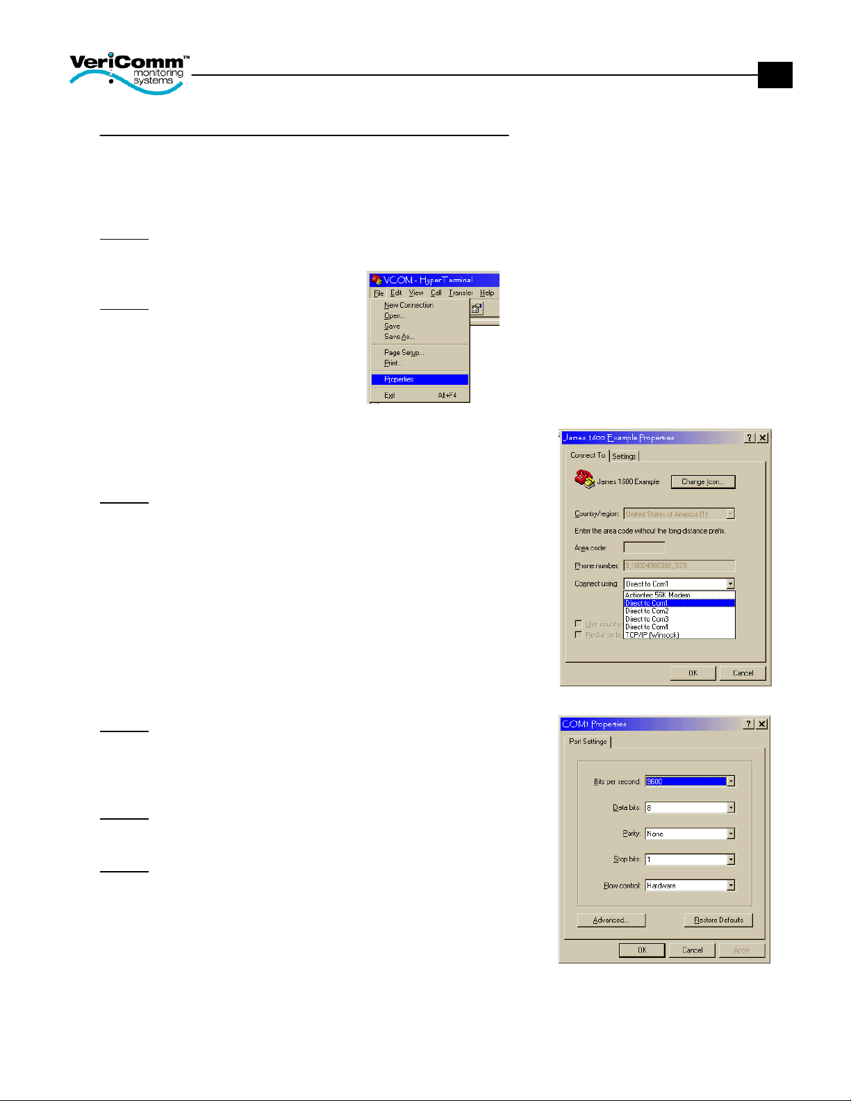
HyperTerminal..................................................................................4
To Create a New Connection................................................................. 4
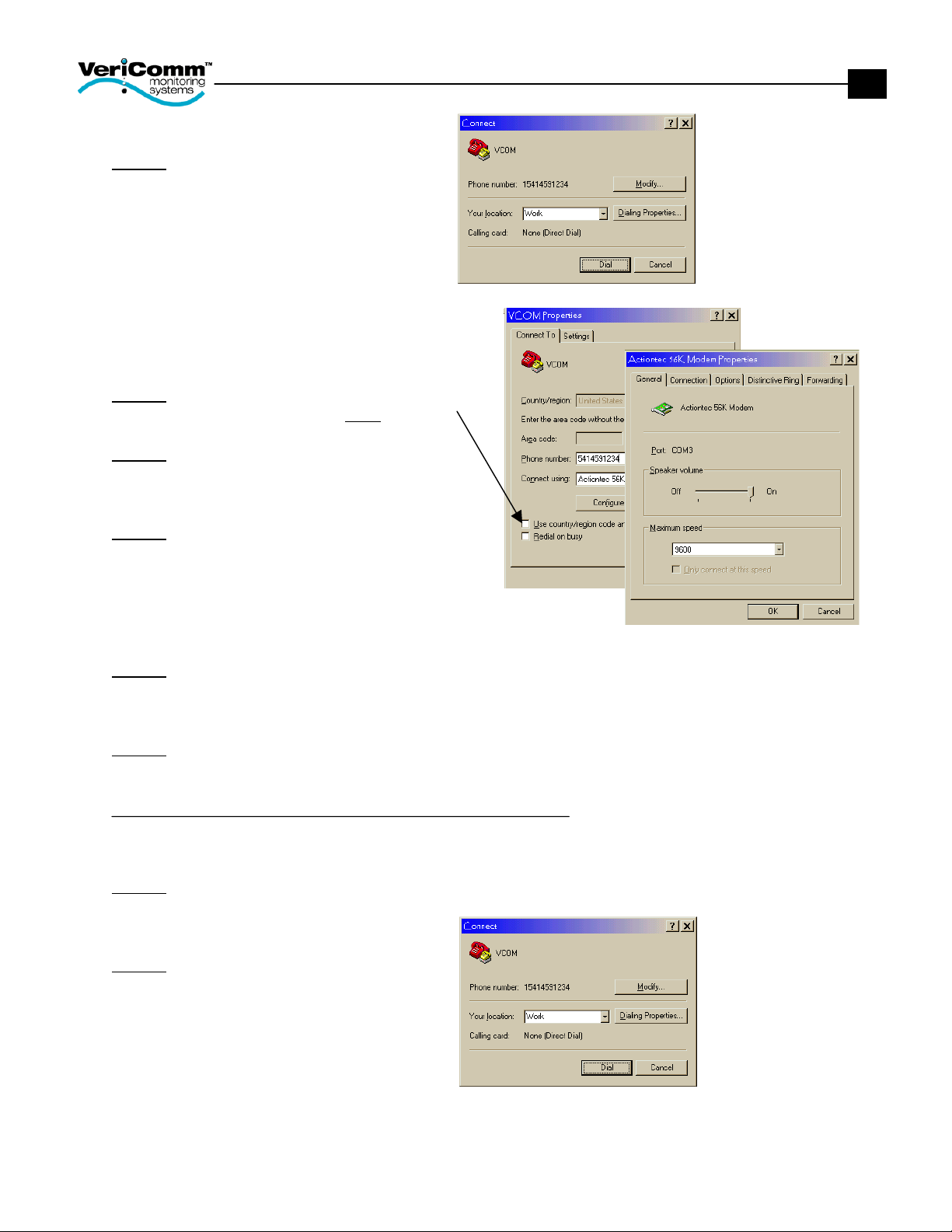
To Connect Remotely to a Custom VCOM Panel................................. 5
To Connect Directly to a Custom VCOM Panel ................................... 6
Login Screen.....................................................................................7
Login Procedure .................................................................................... 7
Run Mode Menu...............................................................................8
1. System Status Displays..................................................................... 8
2. Maintenance Log Entry .................................................................... 8
3. Maintenance Log Report.................................................................. 8
4. Expanded Report Menu.................................................................... 8
5. Enter a Password .............................................................................. 8
6. Initiate a Call Back........................................................................... 8
P. TRINET Program Mode Menu ........................................................ 8
C. MODEM OFF-LINE (Hang Up) ..................................................... 8
Page Select Menu ............................................................................9
System Status Page................................................................................ 9
Individual Status Page(s)....................................................................... 9
Settings.................................................................................................. 9
Flow Data Page(s) ............................................................................... 10
Log Parameters.................................................................................... 10
Inputs & Outputs ................................................................................. 10
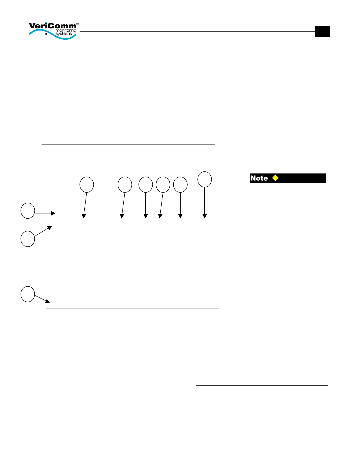
Page Definition & Layout................................................................10
1. Page Description............................................................................. 10
2. PT# ................................................................................................. 10
3. Description ..................................................................................... 10
4. Value .............................................................................................. 10
5. Sts................................................................................................... 11
6. CurTm ............................................................................................ 11
7. PrevTime ........................................................................................ 11
8. Why? .............................................................................................. 11
9. Choices........................................................................................... 11
Adjusting Point Settings..................................................................11
To Force a Digital Point On ................................................................ 12
To Force a Digital Point Off................................................................ 13
To Override a Numeric Point Value.................................................... 14
To Override a Point for a Specified Time............................................ 15
System Status Menu ......................................................................16
To View Details of a Specified Point.................................................. 16
Explain the Point Value (A) ................................................................ 17
Rule Display (F).................................................................................. 17
Change Time/Date (I).......................................................................... 18
Input & Output Displays (K-N)........................................................... 18
Logs (Q,S,U) ....................................................................................... 19
Maintenance Log............................................................................20
Entering Maintenance Notes................................................................ 20
Viewing the Maintenance Log Report................................................. 21
Retrieving Logs...............................................................................22
To Retrieve a Log................................................................................ 22

EIN-CP-VCOM-2
Rev. 1.0 © 3/9/01
4
HyperTerminal
HyperTerminal is designed to satisfy your basic communications needs in an easy-to-use product.
The user interface is similar to most Windows operating systems.
HyperTerminal is typically located in the Start Menu under the Accessories option.
To Create a New Connection
When the VCOM panel is installed and accessed for the first time, a new connection for the site must
be created. A new connection is created by performing the following steps.
Step 1: Type a name that describes the connection (e.g., project name), select any icon, and then
click OK.
•=If the connection description
window is not open, click on
the File menu, and click New
Connection.
Step 2: Enter the phone number to the panel, and then click OK.
•=Leave the ‘Area Code’ box
empty.
•=Enter phone number exactly
how it must be dialed (e.g., if
a 9 is required to access an
outside line or if the area
code is needed for long
distance).

EIN-CP-VCOM-2
Rev. 1.0 © 3/9/01
5
Step 3: Click the Modify button.
Step 4: Be sure the ‘Use country/region code
and area code’ box is NOT checked.
Step 5: Click the Configure button.
Step 6: Change the maximum speed to
9600 and click OK.
Step 7: Click the Cancel button until all of the windows are gone. The HyperTerminal window is now
available.
Step 8: On the File menu, click Save.
To Connect Remotely to a Custom VCOM Panel
After a new connection for the site has been created and saved, the site can now be accessed
remotely. Follow the steps below to establish a connection with the VCOM panel.
Step 1: On the File menu, click Open, and then double-click the connection you want to use.
Step 2: Click Dial.
The computer will now establish a connection with the panel. This may take a few seconds.
(Skip to page 7.)

EIN-CP-VCOM-2
Rev. 1.0 © 3/9/01
6
To Connect Directly to a Custom VCOM Panel
After a new connection for the site has been created and saved, the site can now be accessed
directly. A null modem cable is needed for the direct connection. Connect one end of the null modem
cable to the serial port on the laptop and the other end to the serial port on the telemetry board.
Follow the steps below to directly connect with the VCOM panel.
Step 1: On the File menu, click Open, and then double-click the connection you want to use.
Step 2: Again on the File menu,
click Properties.
Step 3: Click on the ‘Connect using’box and select
the Com Port that the PC is using for the connection.
Step 4: Click on the Configure button and select
9600 bits per second.
Step 5: Click OK.
Step 6: On the Call menu, click Call.
The computer will now establish a connection with the panel.

EIN-CP-VCOM-2
Rev. 1.0 © 3/9/01
7
Login Screen
Once the computer and VCOM panel have made a successful connection, the login screen will be
displayed.
•=A valid user name and
password are required to gain
access to the VCOM control
systems.
•=If you have not received your
user name and password,
please contact Orenco
Systems, Inc.
Login Procedure
To login to the VCOM control system, follow the procedure below:
1. Type the User Name and press the TAB key.
2. Type the Password.
3. Press Enter.
If a mistake is made while entering the User Name or Password, press the ESC key until the cursor
blinks at the User Name.
L0 Ok Std TriNet - copyright 1988-98, ISAC Inc. V4.16E
<============================================================>
TTTTTTTTTTTTT NNN NNN
TTTTTTTTTTTTT NNNN NNN tt
TTT ii NNN N NNN tttttttttt
TTT NNN N NNN tt
TTT r rrrr ii NNN N NNN eeeee tt
TTT rr r ii NNN N NNN eeeeeee tt
TTT rr ii NNN NNNN ee tt
TTT rr ii NNN NNN eeeee tt
by Integrated Systems and Controls Inc.
USER NAME:
PASSWORD:

EIN-CP-VCOM-2
Rev. 1.0 © 3/9/01
8
Run Mode Menu
This main menu is displayed after a successful login. The name of the current page being displayed
will be labeled. The following options are available by pressing the number or letter that corresponds
to the desired mode.
•=To select a menu option,
press the corresponding letter
or number next to the desired
page (e.g., press “1” for the
System Status Displays
page).
•=Access to the Run Mode
Menu options depends on the
password level.
•=The “TRINET” Program Mode
Menu” is for Orenco Systems’
engineers or advanced users.
1. System Status Displays
Current displays of the panel’s activities can be
viewed. Viewing and adjusting parameters will
be done here.
2. Maintenance Log Entry
Any changes or adjustments to the system can
be manually logged for future reference.
3. Maintenance Log Report
All maintenance log entries can be viewed.
4. Expanded Report Menu
Activity, Alarm, and User Logs can be viewed,
downloaded, and converted to Excel files.
5. Enter a Password
Logs you off of the current session, so a new
User Name and Password can be used to log
on.
6. Initiate a Call Back
Instructs the panel to call a predefined number
after the current session is over.
P. TRINET Program Mode Menu
This is where the point rules are created and
stored. Changes made in the Programming
mode by non-authorized operators can void
your system warranty and affect the operation
of your system.
C. MODEM OFF-LINE (Hang Up)
Disconnects the current session with the
controller.
Dls RUN MODE MENU V4.20M
<=============================================================>
1) System Status Displays
2) Maintenance Log Entry
3) Maintenance Log Report
4) Expanded Reports Menu
5) Enter a Password
6) Initiate a Call Back
P) TRINET Program Mode Menu
C) MODEM OFF-LINE (Hang up)

EIN-CP-VCOM-2
Rev. 1.0 © 3/9/01
9
Page Select Menu
The Page Select Menu will be displayed after the System Status Displays page has been selected
from the Run Mode Menu. The Page Select Menu provides access to predefined pages within the
custom application. These pages define various aspects of your system (e.g., inputs, outputs, system
status, settings, flows, etc.) and are available for your viewing.
•=To select a page, press the
corresponding letter next to
the desired page (e.g., press
“A” for the System Status
page).
•=If a letter does not have a
description then the page is
empty and not used in the
program.
•=Pressing the ESC key will
return you to the previous
page.
•=The pages defined on the
Page Select Menu are
custom to your application.
•=Each page contains 16
points. For example, the
System Status page will
display points 1 through 16.
System Status Page
The System Status page provides an overview
of the the entire system, including current
alarm status, pump status, etc.
Individual Status Page(s)
Multiple status pages may be defined for your
particular system. Individual status pages
provide current information for major system
components (e.g., recirc. tanks, dosing tanks,
discharge tanks, final disposal, etc.).
Settings
Multiple setting pages may be defined for your
particular system. Individual setting pages
provide for viewing and adjusting the
parameters for each application (e.g., timers,
pump flow rate, local alarm delay, pager
delays, etc.).
L0 Ok Std PAGE SELECT MENU
<===========================================================>
A) System Status I) Alarm Settings
B) Recirc Tank Status J) Log Parameters
C) Dose Tank Status K) Misc
D) Recirc Tank Settings L)
E) Dose Tank Settings M)
F) Recirc Tank Flow Data N) Analog Inputs
G) Dose Tank Flow Data O) Digital Inputs
H) P) Digital Outputs

EIN-CP-VCOM-2
Rev. 1.0 © 3/9/01
10
Flow Data Page(s)
Multiple flow data pages may exist for your
system. These pages provide detailed flow
data (e.g., pump cycles today, pump time
today, flow today, etc.).
Log Parameters
These pages determine when the system will
record the user logs (e.g., monthly, hourly, and
weekly). The points contained on these pages
are maintained by Orenco Systems, Inc.
Inputs & Outputs
Multiple input and output pages may exist for
your system. These pages display the status
of digital and/or analog inputs and outputs.
Page Definition & Layout
All of the pages under System Status Display have the same appearance. Each of the pages
contains the following nine fields:
•=The point numbers can be
toggled on/off by pressing the
letter “N” and Enter.
•=To see a specific point, press
“P” and Enter. Then enter the
point number and press
Enter.
The following tips apply to all
screens within the TriNet System.
•=ESC exits the current page.
•=CTRL & Z scrolls 16 points
backward.
•=CTRL & W scrolls 16 points
forward.
•=TAB Φmoves cursor in
sequence between control
fields.
•=↵Enter key executes desired
command
1. Page Description
Identifies which page is being viewed (e.g.,
Recirc. Tank Status).
2. PT#
Identifies the program point number. Each
page includes sixteen programming points. If
the point numbers are not displayed, see
NOTE.
3. Description
Describes each program point used.
4. Value
Displays the current value of the point. This
can be displayed as a label (e.g., OK, HiLevel,
OFF, OnCycle, etc.), a unit of measurement
(e.g., min, gal, amps, etc.), a digital value (e.g.,
on or off), a date, or time.
L0 Ok Std SYSTEM STATUS DISPLAY TUE 2/20/01 11:51
<================================================================>
Recirc Tank Status
Pt# Description Value Sts CurTm PrevTm Why?
17 RecAlarmStatus OK A 99:59:59 0:00:02 "OK
18 RecPumpMode OFFCYCL A 0:01:00 0:01:36 Rule
19 RecLeadPosition TWO A 0:00:53 0:03:12 Rule
20
21 RecTimerMode NORMAL A 99:59:59 0:00:00 Rule
22
23 RecActivOffTime 1.5 Min A Rule
24 RecActiveOnTime 1.5 Min A Rule
25
26 Pump#1Status OFF 0:01:01 0:01:36 Rule
27 Pump#1Current 0.0 Amps P209
28 Pump#2Status OFF 0:04:13 0:01:36 Rule
29 Pump#2Current 0.0 Amps P210
30
31
32
Choices: A(auto) O(on) F(off) C(const) P(point) T(timer) N(num) M(menu)
1
2
9
3 4 6 7 8
5

EIN-CP-VCOM-2
Rev. 1.0 © 3/9/01
11
5. Sts
If this column contains a variable, the point can
be changed or adjusted.
6. CurTm
Provides the elapsed time for the current value.
7. PrevTime
Provides the total elapsed time for the previous
point value.
8. Why?
Defines the reason for the value if available
(e.g., rules, inputs, default value, etc.).
9. Choices
These options are available under the “Sts”
column.
Adjusting Point Settings
Most VCOM panels are shipped with standard settings. Parameters may need to be adjusted to meet
the system’s needs. Parameter adjustments are made by using the Choice Menu located at the
bottom of the System Status Display screens. For example, a pump may need to be turned on or a
local audible alarm may need to be turned off, temporarily. A parameter can be adjusted if there is a
letter in the “Sts” column.
•=Changes to parameters must
be made between screen
updates or they will not be
saved. (This can be avoided
by pressing the Enter key
immediately after a letter is
entered in the “Sts” column.)
•=Overriding point values can
severely affect the operation
of your onsite system and will
not allow the TriNet Logic to
control a particular point.
•=If a mistake is made while
changing a parameter, press
ESC.
•=The point numbers can be
toggled on/off by pressing the
letter “N” and Enter.
•=To see a specific point, press
“P” and Enter. Then enter the
L0 Ok Std SYSTEM STATUS DISPLAY TUE 2/20/01 12:14
<================================================================>
Digital Outputs
Pt# Description Value Sts CurTm PrevTm Why?
241 RecircTankPump1 on A 0:00:08 0:04:48 Rule
242 RecircTankPump2 off A 0:01:45 0:01:36 OFF
243 DoseTankPump3 off A 2:19:27 0:04:07 Rule
244 DoseTankPump4 off A 0:47:20 0:03:49 Rule
245 AlarmLight on O 99:59:59 0:00:04 Ovr/Const
246 AudibleAlarm on A 0:02:31 0:00:00 Rule
247
248
249
250
251
252
253
254
255
256
Choices: A(auto) O(on) F(off) C(const) P(point) T(timer) N(num) M(menu)

EIN-CP-VCOM-2
Rev. 1.0 © 3/9/01
12
point number and press
Enter.
To Force a Digital Point On
When a point is forced on, the TriNet Logic for that point is overridden. The point will no longer use the
internal program to determine its state. The point will continue to stay on until it is returned to Auto(A)
state.
1. Using the TAB key or Arrow keys, move the cursor in the “Sts” column to select the point to be
overriden.
2. Type “O” and immediately press Enter.
In this example, point #245, ‘AlarmLight’, will be manually turned on. The alarm light on the panel will
stay on until an “A” is entered at point #245.

EIN-CP-VCOM-2
Rev. 1.0 © 3/9/01
13
•=Changes to parameters must
be made between screen
updates or they will not be
saved. (This can be avoided
by pressing the Enter key
immediately after a letter is
entered in the “Sts” column.)
•=Overriding point values can
severely effect the operation
of your onsite system and will
not allow the TriNet Logic to
control a particular point.
•=If a mistake is made while changing a parameter, press ESC. •=If a mistake is made while
changing a parameter, press
ESC.
•=The point numbers can be
toggled on/off by pressing the
letter “N” and Enter.
•=To see a specific point, press
“P” and Enter. Then enter the
point number and press
Enter.
To Force a Digital Point Off
When a point is forced off, the TriNet Logic for that point is overridden. The point will no longer use the
TriNet Logic to determine its state. The point will continue to stay off until it is returned to Auto(A)
state.
1. Using the TAB key or Arrow keys, move the cursor in the “Sts” column to select the point to be
overriden.
2. Type “F” and immediately press Enter.
In this example, point #246, ‘AudibleAlarm’, will be manually turned off. The audible alarm on the
panel will stay off until an “A” is entered at point #246.
L0 Ok Std SYSTEM STATUS DISPLAY TUE 2/20/01 12:14
<================================================================>
Digital Outputs
Pt# Description Value Sts CurTm PrevTm Why?
241 RecircTankPump1 on A 0:00:08 0:04:48 Rule
242 RecircTankPump2 off A 0:01:45 0:01:36 OFF
243 DoseTankPump3 off A 2:19:27 0:04:07 Rule
244 DoseTankPump4 off A 0:47:20 0:03:49 Rule
245 AlarmLight off A 99:59:59 0:00:04 OFF
246 AudibleAlarm off F 0:02:31 0:00:00 Ovr/Const
247
248
249
250
251
252
253
254
255
256
Choices: A(auto) O(on) F(off) C(const) P(point) T(timer) N(num) M(menu)

EIN-CP-VCOM-2
Rev. 1.0 © 3/9/01
14
•=Changes to parameters must
be made between screen
updates or they will not be
saved. (This can be avoided
by pressing the Enter key
immediately after a letter is
entered in the “Sts” column.)
•=If factory default settings
need severe adjustments, the
operator should contact
Orenco Systems, Inc. to
implement changes.
•=If a mistake is made while
changing a parameter, press
ESC.
•=The point numbers can be
toggled on/off by pressing the
letter “N” and Enter.
•=To see a specific point, press
“P” and Enter. Then enter the
point number and press
Enter.
To Override a Numeric Point Value
Points that can be overriden are usually found on the setting page and contain a numerical label (e.g.,
mins, hrs, GPM, etc.). Overriding a numeric value will cause the TriNet Logic to adjust and implement
changes.
1. Using the TAB key or Arrow keys, move the cursor in the “Sts” column to select the point to be
overriden.
2. Type “C” and immediately press Enter
3. Enter the new constant value, press Enter.
In this example, point #72, ‘Pump3HiAmpLimit’, will be changed from 12.0 Amps to 14.0 Amps.
L0 Ok Std SYSTEM STATUS DISPLAY TUE 2/20/01 12:08
<================================================================>
Dose Tank Settings
Pt# Description Value Sts CurTm PrevTm Why?
65
66 Pump3Flow 30.0 GPM A 30.0
67 Pump4Flow 30.0 GPM A 30.0
68
69
70
71
72 Pump3HiAmpLimit 12.0 Amps C 12.0
73 Pump3LoAmpLimit 8.0 Amps A 8.0
74 Pump4HiAmpLimit 12.0 Amps A 12.0
75 Pump4LoAmpLimit 8.0 Amps A 8.0
76
77 Pump3On&Wait off A 2:13:33 0:03:56 OFF
78 Pump4On&Wait off A 0:41:26 0:03:37 OFF
79
80
Enter constant value (+-xxx.x or Label): 14.0
Choices: A(auto) O(on) F(off) C(const) P(point) T(timer) N(num) M(menu)

EIN-CP-VCOM-2
Rev. 1.0 © 3/9/01
15
•=Changes to parameters must
be made between screen
updates or they will not be
saved. (This can be avoided
by pressing the Enter key
immediately after a letter is
entered in the “Sts” column.)
•=If a mistake is made while
changing a parameter, press
ESC.
•=The point numbers can be
toggled on/off by pressing the
letter “N” and Enter.
•=To see a specific point, press
“P” and Enter. Then enter the
point number and press
Enter.
To Override a Point for a Specified Time
This procedure overrides the TriNet Logic and changes the value of a point for a specified period of
time and then returns it to the previous value. This can be used for both digital and numeric values.
1. Using the TAB key or Arrow keys, move the cursor in the “Sts” column to select the point to be
overriden.
2. Type “T” and immediately press Enter.
3. Type “O” (on), “F” (off), the desired numeric value or the label, and press Enter.
4. Enter the length of Time (if seconds are needed, enter the number of seconds, such as, 120), if
minutes or hours are needed, enter value with a colon, (such as, HH:MM); then press Enter.
In this example, point #241, the ‘RecircTankPump1’, will be turned on for 120 seconds; then it will
revert back to its auto value.
L0 Ok Std SYSTEM STATUS DISPLAY TUE 2/20/01 12:36
<================================================================>
Digital Outputs
Pt# Description Value Sts CurTm PrevTm Why?
241 RecircTankPump1 off T 0:01:03 0:00:38 Rule
242 RecircTankPump2 off A 0:04:15 0:01:36 Rule
243 DoseTankPump3 off A 2:41:10 0:04:07 Rule
244 DoseTankPump4 off A 1:09:03 0:03:49 Rule
245 AlarmLight off A 0:21:25 0:00:11 OFF
246 AudibleAlarm off A 0:24:14 0:00:00 Rule
247
248
249
250
251
252
253
254
255
256
Enter Override Time (hh:mm or xxx secs): 120
Choices: A(auto) O(on) F(off) C(const) P(point) T(timer) N(num) M(menu)

EIN-CP-VCOM-2
Rev. 1.0 © 3/9/01
16
System Status Menu
A point can be evaluated in detail using the menu option on the choices. The rules for the point can
be displayed. The type of information presented is useful for various troubleshooting procedures. The
cursor must be placed in the “Sts” column of the point for evaluation. Common functions are as
follows:
•=If a mistake is made while
entering a choice, press ESC.
•=The point numbers can be
toggled on/off by pressing the
letter “N” and Enter.
•=To see a specific point, press
“P” and Enter. Then enter the
point number and press
Enter.
To View Details of a Specified Point
1. Using the TAB key or Arrow keys, move the cursor in the “Sts” column to select the point to be
evaluated.
2. Type “M” in the “Sts” Column and immediately press Enter.
The current value of the selected point is displayed.
•=The options on the System
Status Menu not described in
this manual are not for an
operator’s use. Changing
information on these pages
may void the warranty.
•=If a mistake is made while
entering an option, press
ESC.
•=Pressing the ESC key at
anytime will return to the
previous screen.
L0 Ok Std SYSTEM STATUS DISPLAY TUE 2/20/01 16:22
<================================================================>
System Status
Pt# Description Value Sts CurTm PrevTm Why?
1 AlarmStatusRec LowLvl M_ 0:0:10 0:59:59 P17
2 PumpModeRec OFF 0:01:10 0:01:36 P18
3
4 RecFlowToday 14769 Gal P91
5
6 AlarmStatusDose OK 99:59:59 0:00:56 P33
7 PumpModeDose PUMPOFF 0:42:28 0:03:53 P36
8
9 DoseFlowToday 1437.0 Gal P107
10
11 AlarmStatGrease OK 99:59:59 0:00:00 "OK
12
13 AlarmStatSeptic OK 99:59:59 0:00:00 "OK
14
15
16
Choices: A(auto) O(on) F(off) C(const) P(point) T(timer) N(num) M(menu)
L0 Ok Std SYSTEM STATUS MENU
<================================================================>
Point# 1 (AlarmStatusRec) is now: LowLvl
A) Explain the Point Value
B) Page Select Menu K) Analog Input Display
C) Time Program Display L) Analog Output Display
D) Holiday Display M) Digital Input Display
E) Optimizer Display N) Digital Output Display
F) Rule Display O) Point Timer Display
G) Enter/Edit Time Program V) Network Values Display
H) Enter/Edit Holiday Q) Alarm Log
I) Change Time/Date S) Activity Log
J) PID Logic Display U) User Log
W) Sequencer Display T) Composite Time Prog Disp
R) TRINET Run Mode Menu P) TRINET Program Mode Menu

EIN-CP-VCOM-2
Rev. 1.0 © 3/9/01
17
Explain the Point Value (A)
This option will describe the program logic that is currently responsible for the point’s valvue. All other
value possibilities are listed.
•=If no data is available, a
message of “No Data to
Report” will be displayed.
•=Pressing the ESC key at
anytime will return to the
previous screen.
•=Pressing the ESC key at
anytime will return to the
previous screen.
Rule Display (F)
The rules for the point can be displayed. The rule controlling the point will be displayed first. The
other rules that apply to the point can be displayed by repeatedly pressing the Enter key.
•=If no rules are controlling a
point, a message of “No Rule
Applies!” will be displayed.
•=Pressing the ESC key at
anytime will return to the
previous screen.
POINT VALUE EXPLANATION
=======================
THU 3/1/01 11:34 Std
Point# 1 (AlarmStatusRec) is now: LowLvl
DUE TO Rule 119
Logic that exists for this point:
Rule Changes Point
Used by Rule
Point Definition Default
Press any key to continue
L0 Ok Std CONTROL RULE SUMMARY
<=================================================================>
POINT: 1 (AlarmStatusRec) {LowLvl } RULE: 119 {true}
-- IS --
"LowLvl
-- IF --
P35 (BottomFloat) {OK} = "OK
-- AND --
P179 (RO) {off} = OFF
LIST RULE # (1-256): 0

EIN-CP-VCOM-2
Rev. 1.0 © 3/9/01
18
Change Time/Date (I)
The time and date are used in the programing, so it is necessary for the VCOM panel to have the
correct time and date. The clock is 24-hour and does not require AM or PM.
•=TriNet’s date format is
mm/dd/yy.
•=The clock must include the
colon between the hour and
minutes.
•=Define whether the current
setting is standard time (S) or
daylight savings time (D).
•=Press the TAB key to switch
between fields.
•=Press the Enter key to save
the changes.
Input & Output Displays (K-N)
These pages will display the current values for the analog/digital inputs or outputs.
L0 Ok Std SYSTEM DEFINITIONS
<================================================================>
Current Date: 2/21/01
Current Time: 15:42
Standard/Daylight Time(S,D): S
TRINET V4.16E ANALOG INPUT REPORT 2/21/01
15:44
# Description Status
1 Pump1CS 11.3 Amps
2 Pump2CS 0.0 Amps
3 Pump3CS 0.0 Amps
4 Pump4CS 0.0 Amps
5 Not Used
6 Not Used
7 5 VDC PS 5.0
8 24 VDC PS 23.8
Press ESC to cancel, or any other key to continue

EIN-CP-VCOM-2
Rev. 1.0 © 3/9/01
19
Logs (Q,S,U)
These pages will display the activity log, alarm log, or user log.
The activity log will report input or output activity with a date and time stamp. To view an activity log,
the cursor must be on the digital input/output to be monitored before entering the System Status
Menu.
The alarm log will report any PC board failures (e.g., low battery, power failures).
The user log is where the programming data is reported (e.g., level alarms, daily pump run times,
etc.). The user logs will be separated into individual pages. This menu is where user log numbers
can be determined and viewed before downloading.
•=If no data is available to
report from the logs, a
message of “No Data to
Report” will be displayed.
•=Pressing the ESC key at
anytime will return to the
previous screen.
TRINET V4.16E ACTIVITY LOG REPORT 2/20/01 16:53
POINT 245 (AlarmLight) ACTIVITY DATA
ACTIVITY logged: Start Start End End
Cause of Activity Item Value Date Time Date Time
PT-ON ,AlarmLight 245 on 2/20/01 12:14:40 2/20/01 12:14:51
Press ESC to cancel, or any other key to continue

EIN-CP-VCOM-2
Rev. 1.0 © 3/9/01
20
Maintenance Log
Any changes or adjustments to the system can be manually logged for future reference.
Entering Maintenance Notes
1. Press “2” from the Run Mode Menu.
2. Type the desired note.
3. Press Enter.
•=Notes cannot be over 50
characters.
L0 Ok Std RUN MODE MENU V4.16E
<===========================================================>
1) System Status Displays
2) Maintenance Log Entry
3) Maintenance Log Report
4) Expanded Reports Menu
5) Enter a Password
6) Initiate a Call Back
P) TRINET Program Mode Menu
C) MODEM OFF-LINE (Hang up)
L0 Ok Std MAINTENANCE LOG
<===========================================================>
User Name: sammyT
Date/Time: 2/8/01 11:26:18
Notes: everything looks OK
This manual suits for next models
1
Table of contents
Popular Control Panel manuals by other brands

Panasonic
Panasonic AY-RP500 installation manual

HEIDENHAIN
HEIDENHAIN ND 1100 - V2.15.0 GUIDE Quick reference guide

Sony
Sony UCP-8060 Operation manual

HUBBELL LIGHTING
HUBBELL LIGHTING CX16 Quick Start, Installation & Programming Guide

Olimpia splendid
Olimpia splendid Bi2 AQUADUE Control Hardware manual

BFT
BFT THALIA BT A80 installation manual

Honeywell
Honeywell IQ8Control C Installation instruction

Side-Power
Side-Power S-linkControl Panel PJC211 Installation and user manual

Satel
Satel Versa Programming manual

Prosense
Prosense S-DP32 user manual

U-Prox
U-Prox IC A Installation and programming manual

Siemens
Siemens SINAMICS BOP-2 operating instructions