OSS PCIe 4.0 Quad M.2 Carrier User manual


One Stop Systems
OSS-PCIe4-ADP-x16-M.2-4 2
Table of Contents
Preface.................................................................................................................................................................................... 4
Advisories ............................................................................................................................................................................................................4
Safety Instructions ...............................................................................................................................................................................................5
Protecting Against Electrostatic Discharge ..........................................................................................................................................................6
1Product Information....................................................................................................................................................... 7
1.1 Removal Tray ............................................................................................................................................................................................7
1.2 PCIe M.2 Carrier Card................................................................................................................................................................................8
1.2.1 OSS-537 Board................................................................................................................................................................................8
1.2.2 OSS-568 Board................................................................................................................................................................................8
1.3 Features ....................................................................................................................................................................................................9
1.4 General Specification ................................................................................................................................................................................9
1.5 Block Diagram .........................................................................................................................................................................................10
1.6 Dimensions..............................................................................................................................................................................................10
1.7 M Key Connector.....................................................................................................................................................................................11
2Hardware Requirements ...............................................................................................................................................12
3Software Requirements ................................................................................................................................................12
4Hardware Installation ...................................................................................................................................................13
4.1 Installation-Procedures Overview........................................................................................................................................................... 13
4.4 Prepare PCIe Carrier Card .......................................................................................................................................................................14
4.5 Remove the canister ...............................................................................................................................................................................14
4.6 Install M.2 module ..................................................................................................................................................................................15
4.7 Secure the Media ....................................................................................................................................................................................15
4.8 Configure SW1 Dipswitch........................................................................................................................................................................16
4.8.1 SW1 Dipswitch .............................................................................................................................................................................16
4.9 Connect Data Cables ...............................................................................................................................................................................16
4.10 Plugin the PCIe carrier board.............................................................................................................................................................17
4.11 Connect Power to Mezzanine Card....................................................................................................................................................18
4.13 Install Canister ...................................................................................................................................................................................19
4.14 Power ON the computer....................................................................................................................................................................19
5Hardware Check............................................................................................................................................................20

One Stop Systems
OSS-PCIe4-ADP-x16-M.2-4 3
5.1 LED Definition .........................................................................................................................................................................................20
6Verify OSS Device on Windows OS ................................................................................................................................21
6.1 Device Manager ......................................................................................................................................................................................21
7Verify M.2 Media on Windows OS.................................................................................................................................22
7.1 Device Manager ......................................................................................................................................................................................22
7.2 Disk Management...................................................................................................................................................................................23
7.3 Storage Spaces........................................................................................................................................................................................23
7.4 Check Temperature.................................................................................................................................................................................24
8Verify OSS Device on Linux OS.......................................................................................................................................25
9Verify M.2 Media on Linux OS .......................................................................................................................................26
9.1 Check Temperature.................................................................................................................................................................................28
9.2 Check OSS Device Speed and Linkwidth.................................................................................................................................................29
9.3 Check M.2 Speed and Linkwidth ............................................................................................................................................................ 30
9.4 PCIe Device Detailed Info........................................................................................................................................................................31
9.5 Smartctl...................................................................................................................................................................................................32
10 Benchmark Performance (Read & Write).......................................................................................................................33
10.1 Disk Management Tool.................................................................................................................................................................33
11 FAQ’s ............................................................................................................................................................................35
12 Contacting Technical Support........................................................................................................................................36
11 Returning Merchandise to One Stop Systems................................................................................................................36
12 Shipping / transporting the card....................................................................................................................................37
11 APPENDIX A Compliance.............................................................................................................................................37

One Stop Systems
OSS-PCIe4-ADP-x16-M.2-4 4
Preface
Advisories
Five types of advisories are used throughout this manual to provide helpful information, or to alert you to the potential for hardware damage
or personal injury.
Disclaimer: We have attempted to identify most situations that may pose a danger, warning, or caution condition in this manual. However, One
Stop Systems does not claim to have covered all situations that might require the use of a Caution, Warning, or Danger indicator.
. . .
Note
Important
C.Aut:lo
.n
Warnln1
NOTE
Used
to
ampli
fy
or expla
in
a comment rel
ated
to
procedural
steps
or text.
I
MPORTA
NT
U
sed
to indicate
an
important pie
ce
of
information or special "tip" to help you
CAUT
ION
Used
to
indi
ca
te and preve
nt
the fo
ll
ow
ing procedu
re
or step
fr
om
caus
ing damage
to
the
equipment.
WAR
NIN
G
U
sed
to indi
ca
te
and preventthe fo
ll
ow
ingstep
from
causing injury.
DA
N
GER
or
STOP
Used
to
indicate and preve
nt
the following step
from
caus
ing
se
rio
us
injury or
sign
ifi
ca
nt
da
ta
lo
ss

One Stop Systems
OSS-PCIe4-ADP-x16-M.2-4 5
Safety Instructions
Always use caution when servicing any electrical component. Before handling the One Stop Systems Expansion chassis, read the following
instructions and safety guidelines to prevent damage to the product and to ensure your own personal safety. Refer to the “Advisories” section
for advisory conventions used in this manual, including the distinction between Danger, Warning, Caution, Important, and Note.
Always use caution when handling/operating the computer. Only qualified, experienced, authorized electronics personnel should access the
interior of the computer and expansion chassis.
WARNING
Never modify or remove the radio frequency interference shielding from your workstation or expansion unit. To do so
may cause your installation to produce emissions that could interfere with other electronic equipment around your
system.
When Working Inside a Computer
Before taking covers off a computer, perform the following steps:
Turn off the computer and any peripheral devices.
Disconnect the computer and peripheral power cords from their AC outlets or inlets to prevent electric shock or system board damage.
In addition, take note of these safety guidelines when appropriate:
To help avoid possible damage to systems boards, wait five seconds after turning off the computer before removing a component, removing a
system board, or disconnecting a peripheral device from the computer.
When you disconnect a cable, pull on its connector or on its strain-relief loop, not on the cable itself. Some cables have a connector with locking
tabs. If you are disconnecting this type of cable, press in on the locking tabs before disconnecting the cable. As you pull connectors apart, keep
them evenly aligned to avoid bending any connector pins. Also, before connecting a cable, make sure both connectors are correctly oriented
and aligned.
CAUTION
Do not attempt to service the system yourself except as explained in this manual. Follow installation instructions
closely.

One Stop Systems
OSS-PCIe4-ADP-x16-M.2-4 6
Protecting Against Electrostatic Discharge
Electrostatic Discharge (ESD) Warning
Electrostatic Discharge (ESD) is the enemy of semiconductor devices. You should always take precautions to eliminate
any electrostatic charge from your body and clothing before touching any semiconductor device or card by using an
electrostatic wrist strap and/or rubber mat.
Static electricity can harm system boards. Perform service at an ESD workstation and follow proper ESD procedures to reduce the risk of
damage to components. One Stop Systems strongly encourages you to follow proper ESD procedures, which can include wrist straps and
smocks, when servicing equipment.
You can also take the following steps to prevent damage from electrostatic discharge (ESD):
When unpacking a static-sensitive component from its shipping carton, do not remove the component’s anti-static packaging material until you
are ready to install the component in a computer. Just before unwrapping the anti-static packaging, be sure you are at an ESD workstation or
are grounded.
When transporting a sensitive component, first place it in an anti-static container or packaging.
Handle all sensitive components at an ESD workstation. If possible, use anti-static floor pads and workbench pads.
Handle components and boards with care. Do not touch the components or contacts on a board. Hold a board by its edges or by its metal
mounting bracket.

One Stop Systems
OSS-PCIe4-ADP-x16-M.2-4 7
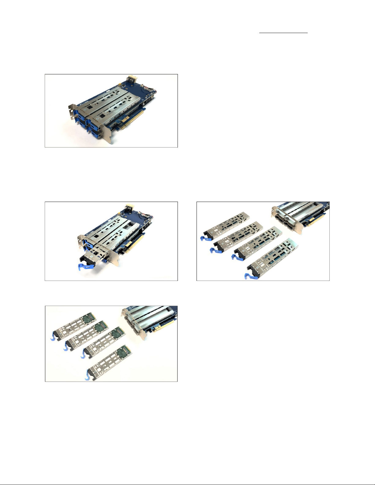
1 Product Information
PCIe x16 Gen 4 add-in card supporting dual Gen 4 hot-swap M.2 drives in removable carriers and dual SFF-8643 connectors supporting
additional NVMe expansion. The hot-swap removable carriers provide interchangeability and flexibility at Gen 4 M.2 speeds for edge
applications while providing scalability through the additional SFF-8643 internal connections.
1.1 Removal Tray

One Stop Systems
OSS-PCIe4-ADP-x16-M.2-4 8
1.2 PCIe M.2 Carrier Card
1.2.1 OSS-537 Board
1.2.2 OSS-568 Board

One Stop Systems
OSS-PCIe4-ADP-x16-M.2-4 9
1.3 Features
•Quad PCIe 4.0 NVMe M.2 slots
•Hot-swap removable drive carriers
•Operates at up to 512Gb/s at PCIe 4.0 speeds
•Supports M.2 2242/2260/2280/22110/E1.S drives
•Supports PCIe 3.0 backward compatibility
1.4 General Specification
Form Factor PCIe 4.0 x16 dual-width add-in card
Dimensions 8.10” x 4.38” (20.6 x 11.1 cm)
Bandwidth Up to 512Gb/s
Drive Form Factors Drive form factors supported:
•PCIe 4.0 NVMe M.2 2242, 2260, 2280, 22110
•PCIe 3.0 NVMe M.2 2242, 2260, 2280, 22110
Connectors PCIe x16 card edge connector
Dual SFF-8643 internal connectors (per board)
Compliant to PCI-SIG PCI Express® External Cable Specification 4.0
Bracket Standard full-height, dual-width
PCIe Switch Broadcom PLX PEX 88032
16 GT/s 32-Lane PCIe 4.0 Switch
DMA controller
SSC Isolation
Power Consumption 60W
Operating Temperature 0°C to 40°C (200LFM airflow required) based on 1.7°C/W
Storage Temperature -40°C to 85°C
Operating Humidity 20% to 80% relative humidity non-condensing
Storage Humidity 20% to 80% non-condensing
Agency Compliance Designed to meet the following agency standards:
•FCC –Part 15 Class A, 47CFR; Canada ICES-003, issue 4, Class A; Japan: VCCI, Class A’ CE Emissions
2004-108EC
•UL/IEC 60950-1; Canada: CSA C22.2 No. 60950-1; Argentina: IEC60950-1; IEC 60950-1 (CB
Certificate and CB Test Report)
•CE Mark (EN55022 Class A, EN60950-1, EN55024, EN61000-3-2, EN61000-3-3)
•CISPR 22, CISPR 24, Class A; Australia/New Zealand AS/NZS CISPR 22, Class A
•RoHS 6 of 6 compliance (Directive 2002/95/EC)
•WEEE (EU 2012/19) & RoHS 3 (EU 2015/863)
Supported Operating
Systems
Windows 10 & Windows 10 Pro
Windows 2012 Server
Ubuntu 16x

One Stop Systems
OSS-PCIe4-ADP-x16-M.2-4 10
1.5 Block Diagram
1.6 Dimensions

One Stop Systems
OSS-PCIe4-ADP-x16-M.2-4 11
1.7 M Key Connector
The OSS-537 and OSS-568 boards support M key edge connector

One Stop Systems
OSS-PCIe4-ADP-x16-M.2-4 12
2 Hardware Requirements
This section provides the hardware parts needed for the OSS-537 board to work. It is strictly recommended to follow and use the hardware
requirements listed below for the board to operate properly.
1. M.2 NVME SSD (Gen 4)
2. Recommended: Server type computer
3. Optional: Standard workstation (with x16 Gen4 PCIe slot) with good air flow and cooling.
Your computer must have sufficient cooling and airflow to prevent overheating of the M.2 media.
Operating
Temperature
0°C to 40°C (200LFM airflow required) based on 1.7°C/W.
For standard workstation, it is highly recommended using 20 CFM Fan or higher
You can measure the airflow by using an inexpensive gadget called “Anemometer Handheld Wind Speed Mete.”
3 Software Requirements
1. Computer running Windows Server or Windows 10 and Windows 10 Pro
a. Windows Pro, driver is loaded automatically when card is installed and detected.
b. On Windows Server, requires no driver. OS loads the driver automatically.
2. Centos 7
3. Ubuntu 16

One Stop Systems
OSS-PCIe4-ADP-x16-M.2-4 13
4 Hardware Installation
The following steps will guide you through the installation of your M.2 PCIe carrier board.
4.1 Installation-Procedures Overview
Following steps provide the exact sequence that needs to be followed:
1. Set the Quad M.2 Carrier board on a sturdy surface
2. Remove the module canister
3. Install the M.2 onto the circuit board
4. Secure the M.2 onto the circuit board
5. Turn OFF computer before installation
6. Remove cover from the computer
7. Remove the corresponding slot cover from computer chassis
8. Configure SW1 Dipswitch
9. Plug-in PCIe carrier board and secure it.
10. Slide the canister back into the PCIe carrier board
11. Power ON the computer
12. Perform Hardware check (Verify LED indicators)
13. Verify device installation (i.e., Windows Device Manager or Linux lspci tree)
One Stop Systems
OSS-PCIe4-ADP-x16-M.2-4 14
4.4 Prepare PCIe Carrier Card
Place the “Quad M.2 Carrier” board on a sturdy surface
4.5 Remove the canister
Remove the tray / canister from the carrier board by pulling the tab (lever or ejector handle) to disengage.
Flip the canister to access the circuit board

One Stop Systems
OSS-PCIe4-ADP-x16-M.2-4 15
4.6 Install M.2 module
Align the M.2 Key edge connector to the M.2 key edge socket on the circuit board
Slowly insert the media at ~30-degree position into the connector socket until it is fully seated.
4.7 Secure the Media
Secure the M.2 media.
Follow the steps below on how to install the canister in the PCIe card carrier in the PCIe cards in the computer.
IMPORTANT! It is important to install the PCIe Quad M.2 Carrier first in the computer before installing the canister.

One Stop Systems
OSS-PCIe4-ADP-x16-M.2-4 16
4.8 Configure SW1 Dipswitch
Set the SW1 Dipswitch using the settings below before you install the card in the computer. All toggle switches are set to OFF.
1= OFF , 2= OFF, 3= OFF, 4= OFF
4.8.1 SW1 Dipswitch
Toggle Switch# Description / Purpose ON OFF
1 Flash 0 or Flash 1 SBR select Flash 1 (default) Flash 0
2 Spare switch
3 Spare switch
4 PCIe Switch Debug Serial Port select UART port SDB port
4.9 Connect Data Cables
Plug in the HD Mini SAS cables to the board.
Use two HD Mini SAS Cables.
•Plug in the first cable to the SFF 8643 connectors, see photos below.
•Pay attention to the orientation of the cable connector, it has a small plastic latch that snaps in place when you connect it to the
8643 connectors.

One Stop Systems
OSS-PCIe4-ADP-x16-M.2-4 17
Plug in the second HD Mini SAS cable. Make sure both cables are firmly seated and latched in.
4.10 Plugin the PCIe carrier board
Plug-in the PCIe carrier board to an open / available x16 slot. You can install the PCIe carrier board in a computer (motherboard) or in an OSS
compatible Gen4 expansion unit (i.e., 4UP or EB4400).
Align the x16 and x1 edge connectors on top of the x16 slot connectors on the motherboard and gently push it down until both card edge
connectors are firmly seated.

One Stop Systems
OSS-PCIe4-ADP-x16-M.2-4 18
Secure the bracket with two screws.
4.11 Connect Power to Mezzanine Card
Connect Power to the Mezzanine Card. Use available external “4pin ATX Molex Female” power cable from the power supply and connect that
to the J2 connector on the mezzanine card (OSS-568 board).
NOTE:
The x1 card edge connector is mainly for power. If a PCIe card slot is not available to use for the x1 card edge connector, you must connect the
external Aux power cable to J2 connector. Photos below show the x1 card edge connector plugged-in vs not plugged-in to a card slot.
If the x1 PCIe connector is already plugged-in to a card slot, the external power cable is no longer required.

One Stop Systems
OSS-PCIe4-ADP-x16-M.2-4 19
4.13 Install Canister
•Slide the canister back into the enclosure of the PCIe carrier board.
•Push the lever forward to latch the canister in place.
4.14 Power ON the computer
Prior to powering ON the computer, verify that the PCIe card edge connector is fully seated as shown from the photos below.
Note:
When PCIe 4.0 Quad M.2 Carrier is installed in an OSS expansion unit or plugged-in to an OSS Gen4 expansion backplane, you must apply power
to the OSS expansion unit or board first before powering on the host computer. See diagram below for supported expansion system setup.

One Stop Systems
OSS-PCIe4-ADP-x16-M.2-4 20
5 Hardware Check
Once the host computer has booted up, verify that all LEDs are correctly illuminated on the carrier card. An operational PCIe board will show
the following LEDs illuminated.
1. CE LINK, SSD RST and RESET LED
2. M.2 LINK LEDs
3. D2 LED
5.1 LED Definition
LED Name When ON When OFF
A and B Stat Swap status still in development. Normal for now
Core Stat ARM core running when flashing ARM core not running
CE Card edge link status: solid on when Gen4
•On for Gen4,
•Flashing fast for Gen3,
•Flashing slow for Gen2
Not linked
SSD RST One or more M.2 is seated in the carrier Stuck in reset
PWR GOOD Power is present on the board No Power
M.2 Link LED M.2 media is present / detected can flash at
different rates
M.2 media is missing / not detected. Data cables are not
connected.
This manual suits for next models
1
Table of contents


