Ossila Potentiostat User manual

enabling materials science Ossila.com
Potentiostat
User Manual
Manual version 1.0.A
Product code: T2006A
Product Version 1.0
Software version: 1.0


Potentiostat User Manual
Ossila.com 1 Ossila Limited © 2020
Contents
1. Overview...................................................................................................................................................... 2
2. EC Declaration of Conformity ................................................................................................................... 3
3. Safety............................................................................................................................................................ 6
3.1 Warning .......................................................................................................................................................................... 6
3.2 Use of Equipment .......................................................................................................................................................... 6
3.3 Hazard Icons................................................................................................................................................................... 6
3.4 General Hazards ............................................................................................................................................................ 7
3.5 Power Cord Safety ......................................................................................................................................................... 7
3.6 Servicing.......................................................................................................................................................................... 7
3.7 Health and Safety –Servicing ....................................................................................................................................... 7
4. Requirements.............................................................................................................................................. 8
5. Unpacking.................................................................................................................................................... 8
5.1 Packing List..................................................................................................................................................................... 8
5.2 Damage Inspection........................................................................................................................................................ 8
6. Specifications .............................................................................................................................................. 9
7. System Components ................................................................................................................................ 10
8. Installation ................................................................................................................................................ 11
9. Operation................................................................................................................................................... 11
9.1 Taking a Measurement ............................................................................................................................................... 11
9.2 Software Settings......................................................................................................................................................... 13
9.2.1 Measurement Settings ........................................................................................................................................... 13
9.2.2 Saving and Loading Settings.................................................................................................................................. 14
9.2.3 Graph Controls........................................................................................................................................................ 15
9.2.4 Saving Results ......................................................................................................................................................... 17
9.2.5 Measurement Controls .......................................................................................................................................... 15
9.3 Performing Cyclic Voltammetry of Ferrocene........................................................................................................... 19
9.3.1 Preparing an Electrochemical Cell ........................................................................................................................ 19
9.3.2 Taking a Measurement .......................................................................................................................................... 20
9.4 Maintenance................................................................................................................................................................. 22
10. Troubleshooting........................................................................................................................................ 23
11. Related Products ...................................................................................................................................... 24
12. Revision History........................................................................................................................................ 25

Potentiostat User Manual
Ossila.com 2 Ossila Limited © 2020
1. Overview
Ossila's Potentiostat is low-cost and easy-to-use system for performing cyclic voltammetry
measurements. Cyclic voltammetry is one of the most widely used electrochemical techniques,
providing important information about materials including:
•Reduction and oxidation potentials
•Reversibility of a reaction
•Electron transfer kinetics
•Energy levels of semiconducting polymers
The Potentiostat is capable of outputting potentials up 5 V, and measuring currents as low as 10
nA, allowing for a wide range of material characterisation. The easy-to-use PC software included
with the system allows anyone to perform the measurement.

Potentiostat User Manual
Ossila.com 3 Ossila Limited © 2020
2. EC Declaration of Conformity
We
Company Name: Ossila Limited
Postal Address: Solpro Business Park, Windsor street.
Postcode: S4 7WB
City: Sheffield
Telephone number: +44 (0)114 2999 180
Email Address: info@ossila.com
declare that the DoC is issued under our sole responsibility and
belongs to the following product:
Product: Product Name (Product Code)
Serial number: T2006A-1000-1000-1000-xxxx
Object of declaration:
Potentiostat (T2006A1)
The object of declaration described above is in conformity with
the relevant Union harmonisation legislation:
EMC Directive 2014/30/EU
RoHS Directive 2011/65/EU
Signed:
Name: Dr James Kingsley
Place: Sheffield
Date: 01/10/2019

Potentiostat User Manual
Ossila.com 4 Ossila Limited © 2020
[български] Декларация за съответствие на ЕС
Производител: Ossila Ltd., Solpro Business Park, Windsor Street, S4 7WD, Великобритания
Декларира с цялата си отговорност, че посоченото оборудване съответства на приложимото законодателство на ЕС за хармонизиране, посочено на предходната(-
ите) страница(-и) на настоящия документ.
[Čeština] Prohlášení o shodě EU
Výrobce:
Ossila Ltd., Solpro Business Park, Windsor Street, S4 7WD, Spojené Království
Prohlašujeme na vlastní odpovědnost, že uvedené zařízeni je v souladu s příslušnými harmonizačními předpisy EU uvedenými na předchozích stranách tohoto
dokumentu.
[Dansk] EU-overensstemme lseserklæring
Producent:
Ossila Ltd., Solpro Business Park, Windsor Street, S4 7WD, UK
Erklærer herved, at vi alene er ansvarlige for, at det nævnte udstyr er i overensstemmelse med den relevante EU-harmoniseringslovgivning, der er anført på
den/de foregående side(r) i dette dokument.
[Deutsch] EU-Konformitätserklärung
Hersteller: Ossila Ltd., Solpro Business Park, Windsor Street, S4 7WD, Vereinigtes Königreich
Wir erklären in alleiniger Verantwortung, dass das aufgeführte Gerät konform mit der relevanten EU-Harmonisierungsgesetzgebung auf den vorangegangenen Seiten
dieses Dokuments ist.
[Eesti keel] ELi vastavusavaldus
Tootja: Ossila Ltd., Solpro Business Park, Windsor Street, S4 7WD, UK
Kinnitame oma ainuvastutusel, et loetletud seadmed on kooskõlas antud dokumendi eelmisel lehelküljel / eelmistel lehekülgedel ära toodud asjaomaste ELi
ühtlustamise õigusaktidega.
[Ελληνικά] Δήλωση πιστότητας ΕΕ
Κατασκευαστής: Ossila Ltd., Solpro Business Park, Windsor Street, S4 7WD, Ηνωμένο Βασίλειο
Δηλώνουμε υπεύθυνα όn ο αναφερόμενος εξοπλισμός συμμορφώνεται με τη σχεnκή νομοθεσία εναρμόνισης της ΕΕ που υπάρχει
σnς προηγούμενες σελίδες του
παρόντος εγγράφου.
[Español] Declaración de conformidad UE
Fabricante: Ossila Ltd., Solpro Business Park, Windsor Street, S4 7WD, Reino Unido
Declaramos bajo nuestra única responsabilidad que el siguiente producto se ajusta a la pertinente legislación de armonización de la UE enumerada en las
páginas anteriores de este documento.
[Français] Déclaration de conformitéUE
Fabricant: Ossila Ltd., Solpro Business Park, Windsor Street, S4 7WD, Royaume-Uni
Déclarons sous notre seule responsabilité que le matériel mentionné est conforme à la législation en vigueur de l'UE présentée sur la/les page(s) précédente(s)
de ce document.
[Hrvatski] E.U izjava o sukladnosti
Proizvođač: Ossila Ltd., Solpro Business Park, Windsor Street, S4 7WD, Velika Britanija
Izjavljujemo na vlastitu odgovornost da je navedena oprema sukladna s mjerodavnim zakonodavstvom EU-a o usklađivanju koje je navedeno na prethodnoj(nim)
stranici(ama) ovoga dokumenta.
[Italiano] Dichiarazione diconformità UE
Produttore: Ossila Ltd., Solpro Business Park, Windsor Street, S4 7WD, UK
Si dichiara sotto la propria personale responsabilità che l'apparecchiatura in elenco è conforme alla normativa di armonizzazione UE rilevante indicata nelle pagine
precedenti del presente documento.
[Latviešu] ES atbilstības deklarācija
Ražotājs: Ossila Ltd., Solpro Business Park, Windsor Street, S4 7WD, UK
Ar pilnu atbilclību paziņojam, ka uzskaitītais aprīkojums atbilst attiecīgajiem ES saskaņošanas tiesību aktiem, kas minēti iepriekšējās šī dokumenta lapās.
[Lietuvių k.] ES atitikties deklaracija
Gamintojas: Ossila Ltd., Solpro Business Park, Windsor Street, S4 7WD, UK
atsakingai pareiškia, kad išvardinta įranga atitinka aktualius ES harmonizavimo teisės aktus, nurodytus ankstesniuose šio dokumento
[Magyar] EU-s megfelelőségi nyilatkozat
Gyártó: Ossila Ltd., Solpro Business Park, Windsor Street, S4 7WD, UK
Kizárólagos felelösségünk mellett kijelentjük, hogy a felsorolt eszköz megfelel az ezen dokumentum előző oldalán/oldalain található EU-s összehangolt jogszabályok
vonatkozó rendelkezéseinek.
[Nederlands] EU-Conformiteitsverklaring
Fabrikant: Ossila Ltd., Solpro Business Park, Windsor Street, S4 7WD, UK
Verklaart onder onze uitsluitende verantwoordelijkheid dat de vermelde apparatuur in overeenstemming is met de relevante harmonisatiewetgeving van de EU op
de vorige pagina('s) van ditdocument.
[Norsk] EU-samsvarserklæring
Produsent: Ossila Ltd., Solpro Business Park, Windsor Street, S4 7WD, UK
Erklærer under vårt eneansvar at utstyret oppført er i overholdelse med relevant EU-harmoniseringslavverk som står på de(n) forrige siden(e) i dette
dokumentet.
[Polski] Deklaracja zgodności Unii Europejskiej
Producent: Ossila Ltd., Solpro Business Park, Windsor Street, S4 7WD, UK
Oświadczamy na własną odpowiedzialność, że podane urządzenie jest zgodne ze stosownymi przepisami harmonizacyjnymi Unii Europejskiej, które
przedstawiono na poprzednich stronach niniejszego dokumentu.
[Português] Declaração de Conformidade UE
Fabricante: Ossila Ltd., Solpro Business Park, Windsor Street, S4 7WD, Reino Unido
Declara sob sua exclusiva responsabilidade que o equipamento indicado está em conformidade com a legislação de harmonização relevante da UE mencionada na(s)
página(s) anterior(es) deste documento.
[Română] Declaraţie de conformitate UE
Producător: Ossila Ltd., Solpro Business Park, Windsor Street, S4 7WD, Regatul Unit
Declară pe proprie răspundere că echipamentul prezentat este în conformitate cu prevederile legislaţiei UE de armonizare aplicabile prezentate la pagina/paginile
anterioare a/ale acestui document.
[Slovensky] Vyhlásenie o zhode preEÚ
Výrobca: Ossila Ltd., Solpro Business Park, Windsor Street, S4 7WD, Spojené kráľovstvo
Na vlastnú zodpovednosť prehlasuje, že uvedené zariadenie je v súlade s príslušnými právnymi predpismi EÚ o harmonizácii uvedenými na predchádzajúcich stranách
tohtodokumentu.

Potentiostat User Manual
Ossila.com 5 Ossila Limited © 2020
[Slovenščina] Izjava EU o skladnosti
Proizvajalec: Ossila Ltd., Solpro Business Park, Windsor Street, S4 7WD, UK
s polno odgovornostjo izjavlja, da je navedena oprema skladna z veljavno uskladitveno zakonodajo EU, navedeno na prejšnji strani/prejšnjih straneh tega
dokumenta.
[Suomi] EU-vaatimustenmukaisuusvakuutus
Valmistaja: Ossila Ltd., Solpro Business Park, Windsor Street, S4 7WD, UK
Vakuutamme täten olevamme yksin vastuussa siitä, että tässä asiakirjassa luetellut laitteet ovat tämän asiakirjan sivuilla edellisillä sivuilla kuvattujen
olennaisten yhdenmukaistamista koskevien EU-säädösten vaatimusten mukaisia.
[Svenska] EU-försäkran omöverensstämmelse
Tillverkare: Ossila Ltd., Solpro Business Park, Windsor Street, S4 7WD, Storbritannien
Vi intygar härmed att den utrustning som förtecknas överensstämmer med relevanta förordningar gällande EU-harmonisering som fmns på föregående sidor i detta
dokument

Potentiostat User Manual
Ossila.com 6 Ossila Limited © 2020
3. Safety
3.1 Warning
Warning
•Do NOT connect external voltage sources to the WORKING channel.
•The absolute maximum input voltage for the REFERENCE channel is ±12 V.
•DO NOT apply input while not powered.
3.2 Use of Equipment
The Ossila Potentiostat is designed to be used as instructed. It is intended for use under the
following conditions:
•Indoors in a laboratory environment (Pollution Degree 2)
•Altitudes up to 2000m
•Temperatures of 5°C to 40°C; maximum relative humidity of 80% up to 31°C.
The unit is supplied with a 24 V / 2 A DC power adapter with a power cord for the country of
purchase, in accordance with European Commission regulations and British Standards. Use of any
other electrical power cables, adaptors, or transformers is not recommended.
3.3 Hazard Icons
The following symbols can be found at points throughout the rest of the manual. Note and read
each warning before attempting any associated operations associated with it:
Table 3.1. Hazard warning labels used in this manual.
Symbol
Associated Hazard
Electrical shock
Potentiostat User Manual
Ossila.com 7 Ossila Limited © 2020
3.4 General Hazards
Before installing or operating the Ossila Potentiostat, there are several health and safety
precautions which must be followed and executed to ensure safe installation and operation.
3.5 Power Cord Safety
Emergency power disconnect options: use the power cord as a disconnecting method
and remove from wall. To facilitate disconnect, make sure the power outlet for this cord
is readily accessible to the operator.
3.6 Servicing
If servicing is required, please return the unit to Ossila Ltd. The warranty will be invalidated if:
•Modification or service has taken place by anyone other than an Ossila engineer.
•The Unit has been subjected to chemical damage through improper use.
•The Unit has been operated outside the usage parameters stated in the user
documentation associated with the Unit.
•The Unit has been rendered inoperable through accident, misuse, contamination,
improper maintenance, modification or other external causes.
3.7 Health and Safety –Servicing
Servicing should only be performed by an Ossila engineer. Any modification or alteration
may damage the equipment, cause injury, or death. It will also void your equipment’s
warranty.

Potentiostat User Manual
Ossila.com 8 Ossila Limited © 2020
4. Requirements
Table 4.1 details the power requirements for the system, and the minimum computer
specifications for the Ossila Cyclic Voltammetry software.
Table 4.1. Potentiostat and Ossila Cyclic Voltammetry software requirements.
Power
24 V / 2 A DC (supplied with the system)
Operating Systems
Windows Vista, 7, 8, or 10 (32-bit or 64-bit)
CPU
Dual Core 2.5 GHz
RAM
2 GB
Available Hard Drive Space
110 MB
Monitor Resolution
1280 x 960
Connectivity
USB 2.0
5. Unpacking
5.1 Packing List
The standard items included with the Ossila Potentiostat are:
•The Ossila Potentiostat.
•24 V / 2 A DC power adapter with a cord set specifically for country of operation (UK, USA,
EU, or AU).
•4mm banana cables and crocodile clips.
•USB-B cable.
•USB memory stick pre-loaded with the user manual, USB drivers, QC data, and Ossila Cyclic
Voltammetry software installer.
5.2 Damage Inspection
Examine the components for evidence of shipping damage. If damage has occurred, please
contact Ossila directly for further action. The shipping packaging will come with a shock indicator
to show if there has been any mishandling of the package during transportation.

Potentiostat User Manual
Ossila.com 9 Ossila Limited © 2020
6. Specifications
The Potentiostat specifications are shown in Table 6.1 below.
Table 6.1. Potentiostat specifications.
Potential range
±7.5 V
Potential compliance
±10 V
Applied potential resolution
333 µV
Applied potential accuracy
±10 mV offset
Maximum current
±150 mA
Current ranges
±10 nA to ±150 mA (5 ranges)
Communication
USB-B
Overall Dimensions
Width: 125 mm
Height: 55 mm
Depth: 175 mm
Weight
600 g
Potentiostat User Manual
Ossila.com 10 Ossila Limited © 2020
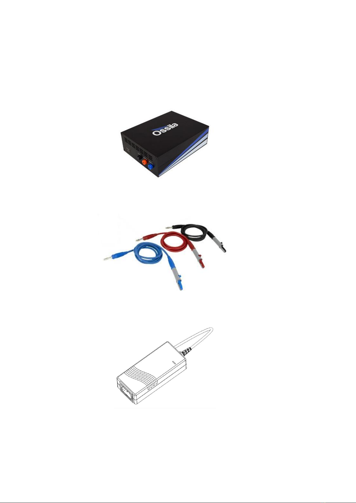
7. System Components
The Ossila Potentiostat is comprised of 4 items: the Ossila Potentiostat, banana cables, power
adaptor, and Ossila Cyclic Voltammetry software.
Figure 7.1. Ossila Potentiostat.
Figure 7.2. Banana cables.
Figure 7.3. 24 V DC power adaptor.

Potentiostat User Manual
Ossila.com 11 Ossila Limited © 2020
Figure 7.4. Ossila Cyclic Voltammetry PC software.
8. Installation
1. Install the Ossila Cyclic Voltammetry software on your PC.
I. Run the file ‘Ossila-Cyclic-Voltammetry-Installer-vX-X-X-X.exe’ on the USB memory
stick provided.
II. Follow the on-screen instructions to install the software.
2. Install the USB drivers on your PC.
I. On the USB memory stick provided, open the ‘SMU-Driver’ folder and run either
‘Windows 32-bit SMU Driver’ for 32-bit operating systems or ‘Windows 64-bit SMU
Driver’ for 64-bit operating systems.
II. Note, on Windows 10 the drivers will install automatically when the unit is
connected.
III. If the drivers fail to install, please refer to the SMU USB Driver Installation Guide
found on the USB memory stick.
3. Connect the 24 V / 2 A DC power adaptor to the power socket on the rear of the unit.
4. Connect the unit to your PC using the provided USB-B cable.
I. If you are using a USB connection and the unit is not detected, please refer to the
SMU USB Driver Installation Guide found on the USB memory stick.
Note: The Ossila Cyclic Voltammetry software and SMU USB drivers can also be
downloaded from https://www.ossila.com/pages/software-drivers.
9. Operation
9.1 Taking a Measurement
1. Add your appropriate electrolyte solution into the electrochemical cell.
2. Place the lid on the cell and insert the working, counter, and reference electrodes.

Potentiostat User Manual
Ossila.com 12 Ossila Limited © 2020
3. Use the banana cables and crocodile clips to connect the sockets on the front of the
Potentiostat to the appropriate electrodes.
I. The red socket connects to the working electrode.
II. The black socket connects to the counter electrode.
III. The blue socket connects to the reference electrode.
4. Start the Ossila Cyclic Voltammetry software. The window shown in Figure 9.2 will open.
5. Enter the appropriate settings for your experiment into the software (explained in more
detail in Section 9.2).
6. Click the ‘Measure’ button.
I. The system will sweep the potential between the working electrode and reference
electrode, whilst measuring the current between the working electrode and
counter electrode, in the follow steps:
Start Potential →Potential Vertex 1 →Potential Vertex 2 →Start Potential
II. This will be repeated for the specified number of cycles.
7. If ‘Save After Measurement’is turned on, the measurement data and settings will be saved
once the sweep has completed.
Figure 9.1. Example of a cyclic voltammetry scan profile for a start potential of 0 V, potential vertex 1 of 0.5
V, potential vertex 2 of -0.5 V, and scan rate of 100 mV/s.
-0.6
-0.5
-0.4
-0.3
-0.2
-0.1
0
0.1
0.2
0.3
0.4
0.5
0.6
0 5 10 15 20
Potential (V)
Time (s)
Potentiostat User Manual
Ossila.com 13 Ossila Limited © 2020
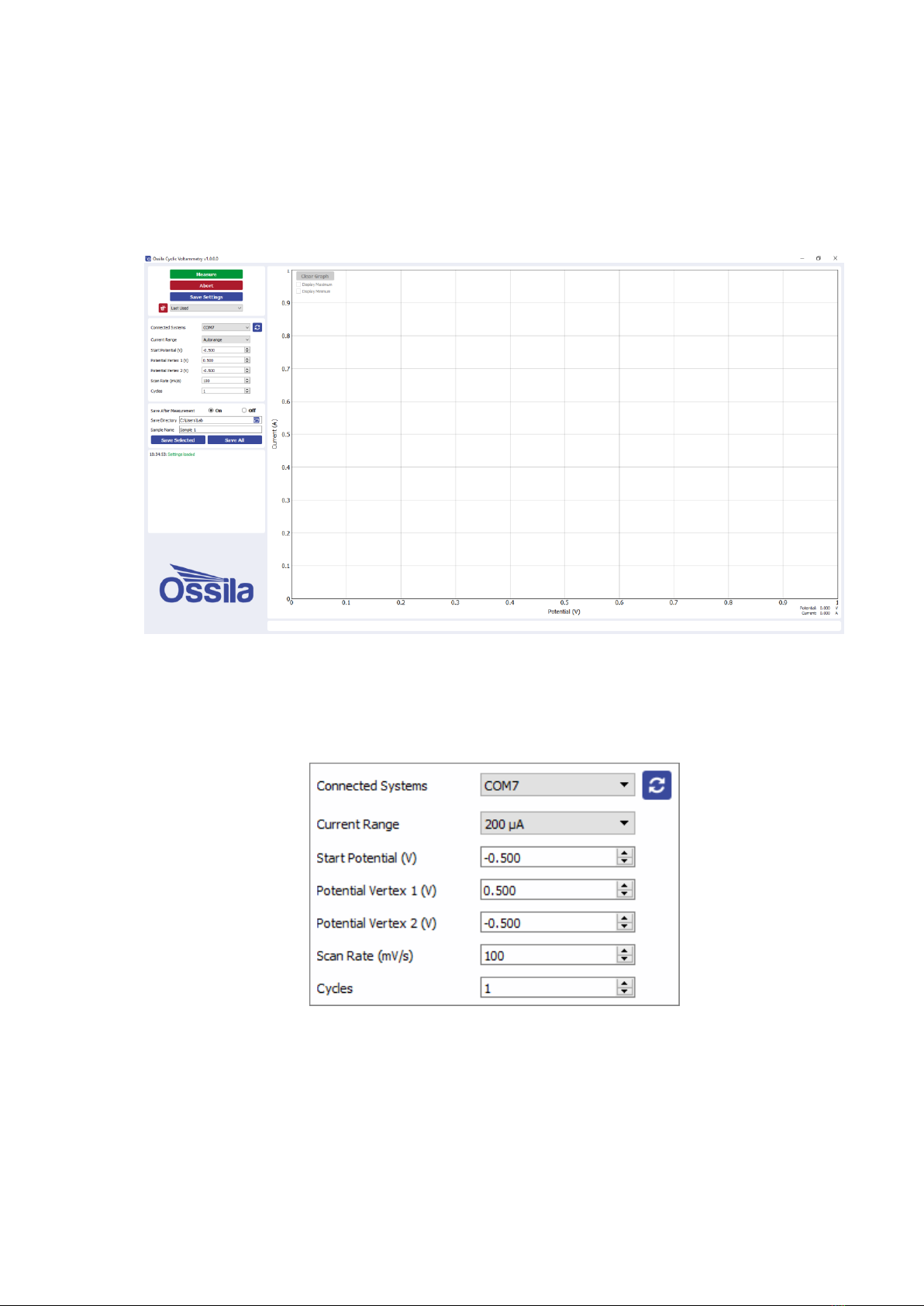
9.2 Software Settings and Controls
There are several settings in the software which must be entered before taking a measurement.
These are found on the panel to the left of the window as shown in Figure 9.2.
Figure 9.2. Ossila Cyclic Voltammetry software.
9.2.1 Measurement Settings
Figure 9.3. Measurement settings.
(I) Connected Systems
•Select the COM port of the connected unit you intend to use.
I. This box will be populated automatically with the addresses of any units connected
to the computer when the software starts.

Potentiostat User Manual
Ossila.com 14 Ossila Limited © 2020
II. To rescan for connected units (in case the connection is changed) click the refresh
icon next to the drop-down box.
(II) Current Range
•Select the range of currents to be used for the measurement or automatic range selection.
I. This defines the upper limit, accuracy, and resolution of the current measurements
that can be performed by the system.
II. Automatic range selection will start on the lowest current range and automatically
switch to higher ranges if the current increases above the maximum for a range.
(III) Start Potential (V)
•The potential in volts at which the measurement starts.
(IV) Potential Vertex 1 (V)
•The first potential in volts at which the scan changes direction.
(V) Potential Vertex 2 (V)
•The second potential in volts at which the scan changes direction.
(VI) Scan Rate (mV/s)
•The rate at which the potential will be changed during the scan, measured in millivolts per
second.
(VII) Cycles
•The number of times the scan will be repeated.
9.2.2 Saving and Loading Settings
Figure 9.4. Controls for saving and loading settings profiles.
(I) Save Settings
•Saves the current settings as a profile that can be loaded quickly for use at another time.
•When clicked, you will be prompted to name the settings profile.

Potentiostat User Manual
Ossila.com 15 Ossila Limited © 2020
I. If the name is already in use, you will be asked if you wish to overwrite the previous
profile.
II. The name cannot contain the characters: \ / : * ? “ < > |
III. You can change the default settings by choosing the name ‘Default’.
•The settings profile will be added to the drop-down box using the given profile name.
(II) Settings Profiles
•Select a saved settings profile from the drop-down box.
I. The settings fields will be populated with the saved values from the selected
profile.
•Settings profiles can be deleted by selecting the profile and then clicking the red ‘delete’
icon next to the drop-down box.
9.2.3 Measurement Controls
Figure 9.5. Controls to start and stop the measurement.
(I) Measure
•Clicking this button will start the measurement using the chosen settings.
•This button cannot be clicked if the software has not detected a unit
(II) Abort
•Stops a measurement that is currently in progress.
9.2.4 Graph Controls
(I) Potential and Current Readout
Whilst the mouse cursor is over the graph, the potential and current of its location are displayed
to the bottom-right of the graph, as shown in Figure 9.6.

Potentiostat User Manual
Ossila.com 16 Ossila Limited © 2020
Figure 9.6. Readout of the potential and current at the mouse cursor location.
(II) Graph Display Controls
By default, the graph will automatically scale the axes of the graph to display all the data within it.
The view can be controlled manually using the following mouse controls:
•Left/Middle click and drag –pan the axes.
•Right click and drag –scale the axes.
•Scroll wheel –scale the axes.
A specific axis can be controlled by using these controls on the axis labels. The axes can be reset
by clicking the ‘A’ button in the bottom-left of the graph, as shown in Figure 9.7.
Figure 9.7. Button to reset the graph axes.
(III) Selecting and Removing Curves
When there are multiple curves on the graph, one of them is considered the active curve. This
curve will be displayed in blue, whilst the other curves will be grey. By default, the last curve to be
measured is the active curve. You can change which curve is the active curve by clicking on any
curve using the left mouse button.

Potentiostat User Manual
Ossila.com 17 Ossila Limited © 2020
To remove an individual curve from the graph, click on it using the left mouse button to make it
the active curve, then press the Delete key.
Figure 9.8. Controls for the graph.
(IV) Clear Graph
•Removes all data from the graph.
(V) Display Maximum/Display Minimum
•Highlights the maximum or minimum point of the active curve and displays the potential
and current values of the point.
9.2.5 Saving Results
Figure 9.9. Saving results.
(I) Save After Measurement
•The program allows for data to be saved automatically, as well as manually once the
measurement is complete.
I. To enable or disable automatic saving, choose the appropriate option from the
drop-down box.
II. For automatic saving, the ‘Save Directory’ and ‘Sample Name’ fields must be filled
in before the measurement can start, these are detailed below.
(II) Save Directory
•Sets the location in which to save the results.
•This can be set either by:
I. Manually typing the directory into the field.
II. Copying and pasting it from your file explorer.

Potentiostat User Manual
Ossila.com 18 Ossila Limited © 2020
III. Clicking the folder icon in the field, which will open a dialog box to allow the
selection of a folder to save to.
(III) Sample Name
•Sets the name of the comma-separated values (.csv) file in which the data will be saved.
I. The name cannot contain the characters: \ / : * ? “ < > |
(IV) Save Selected
•Clicking this button will manually save the measurement results of the active curve.
(V) Save All
•Clicking this button will manually save all the measurement results that are currently
displayed in the graph.
Table of contents
Other Ossila Laboratory Equipment manuals


Popular Laboratory Equipment manuals by other brands


DASIT GROUP
DASIT GROUP FASTER CYTOFAST ELITE Series Operating and maintenance manual

PROEL
PROEL DIRECT100A user manual

Hermle
Hermle Z 446 K user manual

Endecotts
Endecotts Octagon 200CL Installation Qualification Procedures

IKA
IKA Lab disc operating instructions

Thermo Scientific
Thermo Scientific Orbitrap Fusion Lumos Getting started guide

Glas-Col
Glas-Col 099A PV6 Operating and safety instructions

Glas-Col
Glas-Col 099A LC1012 Operating and safety instructions

Agilent Technologies
Agilent Technologies SIPS 10 user guide

Thermo Scientific
Thermo Scientific 88882013 quick start guide

Westlab
Westlab 665-084 product manual

CORNING
CORNING Cell Counter instruction manual