Ossila Dip Coater User manual

enabling materials science ossila.com
Dip Coater
User Manual
Manual Version: 1.0.0
Product code: L2006A1
Product Version: 1.0
Software Version: 1.0

Ossila Dip Coater User Manual
ossila.com 2 Ossila Limited © 2017
Contents
Contents......................................................................................................................................2
1. Overview..............................................................................................................................4
2. EU Declaration of Conformity (DoC) ......................................................................................5
3. Safety...................................................................................................................................8
3.1 Warning...................................................................................................................................8
3.2 Use of Equipment....................................................................................................................8
3.3 Hazard Icons............................................................................................................................8
3.4 General Hazards......................................................................................................................9
3.5 Power Cord Safety...................................................................................................................9
3.6 Servicing..................................................................................................................................9
3.7 Health and Safety –Installation..............................................................................................9
3.8 Health and Safety –Servicing..................................................................................................9
3.9 Crash-Detection Switch.........................................................................................................10
4. Unpacking .......................................................................................................................... 11
4.1 Packing List............................................................................................................................11
4.2 Damage Inspection ...............................................................................................................11
5. Specifications ..................................................................................................................... 12
6. System Components........................................................................................................... 13
7. Installation......................................................................................................................... 14
8. Operating the Dip Coater.................................................................................................... 15
8.1 Dip Coater Diagram...............................................................................................................15
8.2 Dip Coater User Interface .....................................................................................................16
8.3 Practical Operation...............................................................................................................17
8.3.1 Positioning the Dipping Arm .........................................................................................17
8.3.2 Positioning the Reservoir and Dipping Arm..................................................................17
8.3.3 Adjusting Clamp Strength .............................................................................................17
8.3.4 Setting the Solution Height, Substrate Position, and Coating Length. .........................17
8.4 Program Operation...............................................................................................................18
8.4.1 Dip Coater Start Up..............................................................................................................18
8.4.2 ‘Settings’ Mode .............................................................................................................20
8.4.3 ‘Manual’ Mode..............................................................................................................26
8.4.4 ‘Program’ Mode ............................................................................................................30
8.5 Operational Safety ...............................................................................................................41
8.5.1 Pinch Points...................................................................................................................41
8.5.2 Sources of Ignition ........................................................................................................41
9. Maintenance ...................................................................................................................... 41
9.1 Cleaning.................................................................................................................................41
10. Dip Coater Troubleshooting ................................................................................................ 42

Ossila Dip Coater User Manual
ossila.com 3 Ossila Limited © 2017
11. Ossila Contact Details ......................................................................................................... 43
12. List of Related Products ...................................................................................................... 44
13. Revision History.................................................................................................................. 45
Ossila Dip Coater User Manual
ossila.com 4 Ossila Limited © 2017
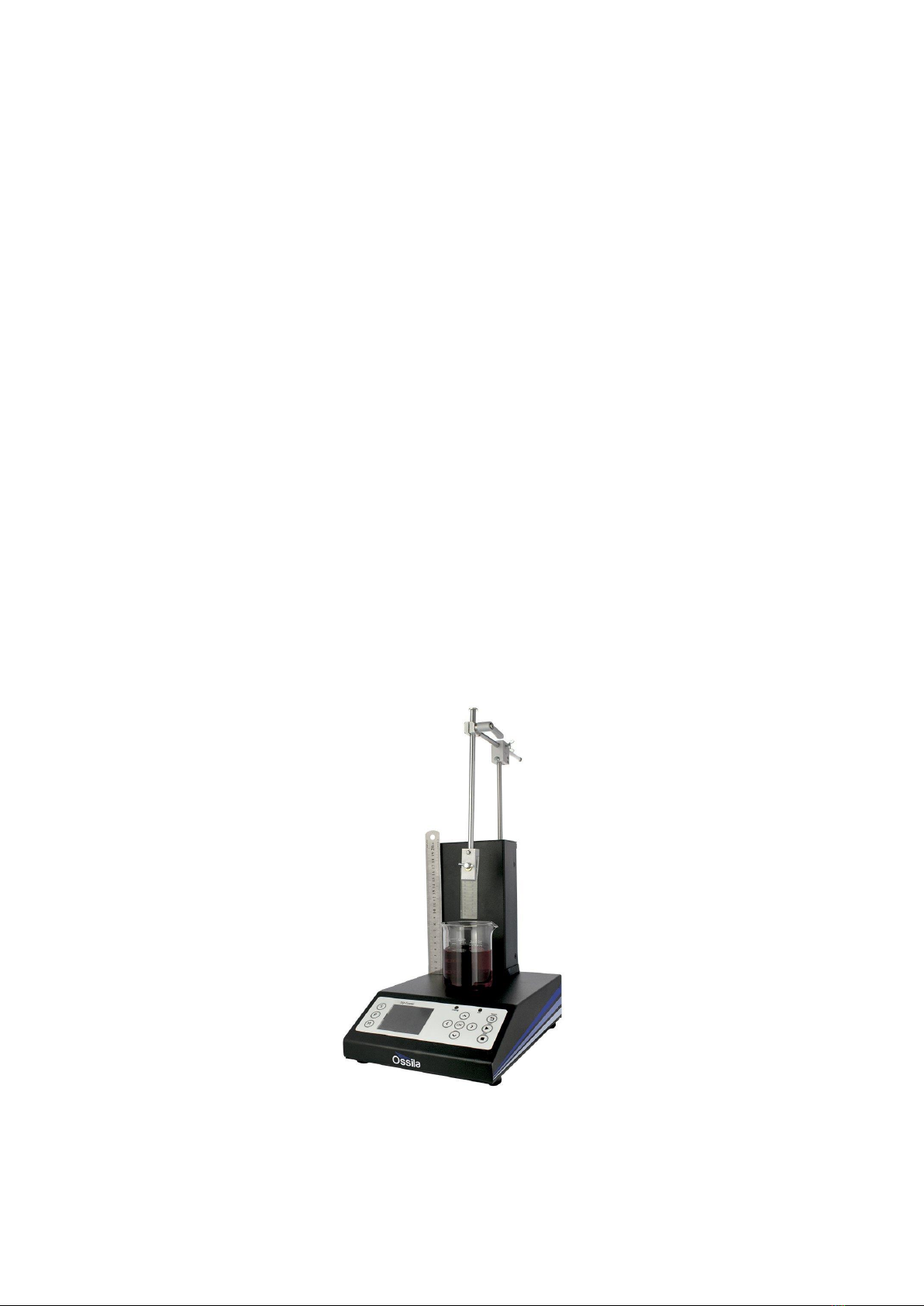
1. Overview
The Ossila Dip Coater is a simple-to-use system designed to deposit thin wet films of solution. Dip
coating involves the controlled immersion and withdrawal of a substrate from a reservoir of solution,
it is widely used in research and development as well as large-scale production.
Film thickness is determined by a balance between several competing forces on the fluid’s surface:
viscous force, capillary forces, and draining forces. Ultimately, film thickness is determined by a
combination of the solution properties and the rate of substrate withdrawal from the solution.
The Ossila Dip Coater can finely control properties such as the immersion speed, dwell, time,
withdrawal speed, and drying time. This gives you accurate control over the final thickness and
properties of the deposited film. Equipped with high-precision motors, the system offers excellent
accuracy and reproducibility for travel speeds and substrate positioning. In addition, the system
provides a wide range of coating speeds (ranging from 0.01mm s-1 to 50mm.s-1), variable withdrawal
rates for graded films, and the option to perform repeat cycles. Additional software features include
user profiles, saveable programmes, crash-sensing software, and changeable working units.
The Ossila Dip Coater’s wide working base means that larger beakers (up to 2 litres in size) can be
used. As the movement distance of the arm is 110mm, you can coat substrates over 10cm in length.
Its clamping mechanism uses a simple spring-loaded clamp for easy substrate removal. Clamp
pressure can be adjusted to suit either delicate or heavy substrates. To ensure maximum user safety,
the Ossila Dip Coater comes with an inbuilt crash-sensing switch. This will stop the motor if the arm
hits an object, protecting your substrates and glassware.

Ossila Dip Coater User Manual
ossila.com 5 Ossila Limited © 2017
2. EU Declaration of Conformity (DoC)
We
Company Name: Ossila Limited
Postal Address: 1st Floor, Northern Block, Solpro Business Park, Windsor Street
Postcode: S4 7WB
City: Sheffield
Telephone number: +44 (0)114 2999 180
Email Address: info@ossila.com
declare that the DoC is issued under our sole responsibility and belongs to
the following product:
Product: Dip Coater (L2006A1)
Serial number: L2006A-1000-1000-1000- xxxx
Object of declaration:
Dip Coater (L2006A1)
The object of declaration described above is in conformity with the relevant
Union harmonisation legislation:
Low Voltage Directive 2014/35/EU
EMC Directive 2014/30/EU
RoHS Directive 2011/65/EU
The following harmonised standards and technical specifications have been
applied:
BS EN ISO 12100:2010 Safety of machinery-General principles for design-Risk assessment and risk
reduction.
Signed:
Name: Dr James Kingsley
Place: Sheffield
Date: 17/10/2018

Ossila Dip Coater User Manual
ossila.com 6 Ossila Limited © 2017
Декларация за съответствие на ЕС
Производител: Ossila Ltd., Solpro Business Park, Windsor Street, S4 7WD, Великобритания
Декларира с цялата си отговорност, че посоченото оборудване съответства на приложимото законодателство на ЕС за хармонизиране, посочено на предходната(-
ите) страница(-и) на настоящия документ.
[Čeština] Prohlášení o shodě EU
Výrobce:
Ossila Ltd., Solpro Business Park, Windsor Street, S4 7WD, Spojené Království
Prohlašujeme na vlastní odpovědnost, že uvedené zařízeni je v souladu s příslušnými harmonizačními předpisy EU uvedenými na předchozích stranách tohoto
dokumentu.
[Dansk] EU-overensstemme lseserklæring
Producent:
Ossila Ltd., Solpro Business Park, Windsor Street, S4 7WD, UK
Erklærer herved, at vi alene er ansvarlige for, at det nævnte udstyr er i overensstemmelse med den relevante EU-harmoniseringslovgivning, der er
anført
på
den/de foregående side(r) i dette dokument.
[Deutsch] EU-Konformitätserklärung
Hersteller: Ossila Ltd., Solpro Business Park, Windsor Street, S4 7WD, Vereinigtes Königreich
Wir erklären in alleiniger Verantwortung, dass das aufgeführte Gerät konform mit der relevanten EU-Harmonisierungsgesetzgebung auf den vorangegangenen
Seiten dieses Dokuments ist.
[Eesti keel] ELi vastavusavaldus
Tootja: Ossila Ltd., Solpro Business Park, Windsor Street, S4 7WD, UK
Kinnitame oma ainuvastutusel, et loetletud seadmed on kooskõlas antud dokumendi eelmisel lehelküljel / eelmistel lehekülgedel ära toodud asjaomaste ELi
ühtlustamise õigusaktidega.
[Ελληνικά] Δήλωση πιστότητας ΕΕ
Κατασκευαστής: Ossila Ltd., Solpro Business Park, Windsor Street, S4 7WD, Ηνωμένο Βασίλειο
Δηλώνουμε υπεύθυνα όn ο αναφερόμενος εξοπλισμός συμμορφώνεται με τη σχεnκή νομοθεσία εναρμόνισης της ΕΕ που υπάρχει
σnς
προηγούμενες σελίδες του
παρόντος εγγράφου.
[Español] Declaración de conformidad UE
Fabricante: Ossila Ltd., Solpro Business Park, Windsor Street, S4 7WD, Reino Unido
Declaramos bajo nuestra única responsabilidad que el siguiente producto se ajusta a la pertinente legislación de armonización de la UE enumerada en las
páginas anteriores de este documento.
[Français] Déclaration de conformitéUE
Fabricant: Ossila Ltd., Solpro Business Park, Windsor Street, S4 7WD, Royaume-Uni
Déclarons sous notre seule responsabilité que le matériel mentionné est conforme à la législation en vigueur de l'UE présentée sur la/les page(s) précédente(s)
de ce document.
[Hrvatski] E.U izjava o sukladnosti
Proizvođač: Ossila Ltd., Solpro Business Park, Windsor Street, S4 7WD, Velika Britanija
Izjavljujemo na vlastitu odgovornost da je navedena oprema sukladna s mjerodavnim zakonodavstvom EU-a o usklađivanju koje je navedeno na prethodnoj(nim)
stranici(ama) ovoga dokumenta.
[Italiano] Dichiarazione di conformità UE
Produttore: Ossila Ltd., Solpro Business Park, Windsor Street, S4 7WD, UK
Si dichiara sotto la propria personale responsabilità che l'apparecchiatura in elenco è
conforme alla normativa di armonizzazione UE rilevante indicata nelle pagine
precedenti del presente documento.
[Latviešu] ES atbilstības deklarācija
Ražotājs: Ossila Ltd., Solpro Business Park, Windsor Street, S4 7WD, UK
Ar
pilnu atbilclību paziņojam, ka uzskaitītais aprīkojums atbilst attiecīgajiem ES saskaņošanas tiesību aktiem, kas minēti iepriekšējās šī dokumenta lapās.
[Lietuvių k.] ES atitikties deklaracija
Gamintojas: Ossila Ltd., Solpro Business Park, Windsor Street, S4 7WD, UK
atsakingai pareiškia, kad išvardinta įranga atitinka aktualius ES harmonizavimo teisės aktus, nurodytus ankstesniuose šio dokumento
[Magyar] EU-s megfelelőségi nyilatkozat
Gyártó: Ossila Ltd., Solpro Business Park, Windsor Street, S4 7WD, UK
Kizárólagos felelösségünk mellett kijelentjük, hogy a felsorolt eszköz megfelel az ezen dokumentum előző oldalán/oldalain található EU-s összehangolt
jogszabályok vonatkozó rendelkezéseinek.
[Nederlands] EU-Conformiteitsverklaring
Fabrikant: Ossila Ltd., Solpro Business Park, Windsor Street, S4 7WD, UK
Verklaart onder onze uitsluitende verantwoordelijkheid dat de vermelde apparatuur in overeenstemming is met de relevante harmonisatiewetgeving van de EU
op de vorige pagina('s) van ditdocument.
[Norsk] EU-samsvarserklæring
Produsent: Ossila Ltd., Solpro Business Park, Windsor Street, S4 7WD, UK
Erklærer under vårt eneansvar at utstyret oppført er i overholdelse med relevant EU-harmoniseringslavverk som står på de(n) forrige siden(e) i dette
dokumentet.
[Polski] Deklaracja zgodności Unii Europejskiej
Producent: Ossila Ltd., Solpro Business Park, Windsor Street, S4 7WD, UK
Oświadczamy na własną odpowiedzialność, że podane urządzenie jest zgodne ze stosownymi przepisami harmonizacyjnymi Unii Europejskiej, które
przedstawiono na poprzednich stronach niniejszego dokumentu.
[Português] Declaração de Conformidade UE
Fabricante: Ossila Ltd., Solpro Business Park, Windsor Street, S4 7WD, Reino Unido
Declara sob sua exclusiva responsabilidade que o equipamento indicado está em conformidade com a legislação de harmonização relevante da UE mencionada na(s)
página(s) anterior(es) deste documento.
[Română] Declaraţie de conformitate UE
Producător: Ossila Ltd., Solpro Business Park, Windsor Street, S4 7WD, Regatul Unit
Declară pe proprie răspundere că echipamentul prezentat este în conformitate cu prevederile legislaţiei UE de armonizare aplicabile prezentate la pagina/paginile
anterioare a/ale acestui document.

Ossila Dip Coater User Manual
ossila.com 7 Ossila Limited © 2017
[Slovensky] Vyhlásenie o zhode preEÚ
Výrobca: Ossila Ltd., Solpro Business Park, Windsor Street, S4 7WD, Spojené kráľovstvo
Na vlastnú zodpovednosť prehlasuje, že uvedené zariadenie je v súlade s príslušnými právnymi predpismi EÚ o harmonizácii uvedenými na predchádzajúcich
stranách tohto dokumentu.
[Slovenščina] Izjava EU o skladnosti
Proizvajalec: Ossila Ltd., Solpro Business Park, Windsor Street, S4 7WD, UK
s polno odgovornostjo izjavlja, da je navedena oprema skladna z veljavno uskladitveno zakonodajo EU, navedeno na prejšnji strani/prejšnjih straneh tega
dokumenta.
[Suomi] EU-vaatimustenmukaisuusvakuutus
Valmistaja: Ossila Ltd., Solpro Business Park, Windsor Street, S4 7WD, UK
Vakuutamme täten olevamme yksin vastuussa siitä, että tässä asiakirjassa luetellut laitteet ovat tämän asiakirjan sivuilla edellisillä sivuilla kuvattujen
olennaisten yhdenmukaistamista koskevien EU-säädösten vaatimusten mukaisia.
[Svenska] EU-försäkran om överensstämmelse
Tillverkare: Ossila Ltd., Solpro Business Park, Windsor Street, S4 7WD, Storbritannien
Vi intygar härmed att den utrustning som förtecknas överensstämmer med relevanta förordningar gällande EU-harmonisering som fmns på föregående sidor i
detta dokument.

Ossila Dip Coater User Manual
ossila.com 8 Ossila Limited © 2017
3. Safety
3.1 Warning
3.2 Use of Equipment
This Dip Coater is designed to be used as instructed, it is intended to be used under the following
conditions:
•Indoors in a laboratory environment (pollution degree 2)
•Altitudes up to 2000 m
•Temperatures of 5°C to 40°C; maximum relative humidity of 80% up to 31°C.
The Dip Coater is supplied with a 24VDC power adapter with a power cord for the country of purchase,
(in accordance with European Commission regulations and British Standards). The use of any other
electrical power cables, adaptors, or transformers is not recommended.
3.3 Hazard Icons
The following symbols can be found at various points throughout this manual. Note and read each
warning before attempting any associated operations associated with it:
Table 3.1 Hazard warning labels used in this manual.
Symbol
Associated Hazard
General warning or caution, which accompanying text will explain
Electrical shock
Pinch point
Warning
•Only use the 24V power adapter and power cord supplied with the unit.
•If using flammable or hazardous solvents, users are expected to be trained in their usage
and carry out a COSHH risk assessment.
•Keep the area around the machine clear, approximately a 150 m clearance above and 150
cm to the sides and behind.
•Keep clear of the machine while it is in operation.
•If using hazardous solvents always use within a fume hood or controlled environment.
•Pinch points when in operation, keep hands clear of moving parts.
•Do not use in an explosive atmosphere

Ossila Dip Coater User Manual
ossila.com 9 Ossila Limited © 2017
3.4 General Hazards
Before installing or operating the Dip Coater, there are several health and safety precautions which
must be followed and executed to ensure safe installation and operation.
WARNING: Improper handling when operating or servicing this equipment can result in serious
injury. Read this manual before operating or servicing this equipment.
I. CAUTION: During operation, the movement of the clamping arm could result in a
pinch point hazard. Caution should be taken whenever the system is in operation.
3.5 Power Cord Safety
I. Emergency power disconnect options: Use the power cord as a disconnecting method
and remove it from the power source. To facilitate disconnect, make sure the power
outlet for this cord is readily accessible to the operator.
3.6 Servicing
If servicing is required, please return the unit to Ossila Ltd. The warranty will be invalidated if:
Modification or service has taken place by anyone other than an Ossila engineer.
The Unit has been subjected to chemical damage through improper use.
The Unit has been operated outside the usage parameters stated in the user documentation
associated with the Unit.
The Unit has been rendered inoperable through accident, misuse, contamination, improper
maintenance, modification or other external causes.
3.7 Health and Safety –Installation
I. Pinch points are present during operation of the dip coater. As a precaution, users
should avoid handling or leaning over the equipment during operation in order
to avoid possible crushing or entanglement of hair and/or clothing.
3.8 Health and Safety –Servicing
I. Servicing should only be performed by an Ossila engineer. Any modification or
alteration may damage the equipment, cause injury, or death. It will also void your
equipment’s warranty.

Ossila Dip Coater User Manual
ossila.com 10 Ossila Limited © 2017
3.9 Crash-Detection Switch
The Dip Coater is fitted with an inbuilt crash-detection switch. The crash-detection switch is housed
within the connection between the mounting arm and stage (see Figure 3.1). During normal
operation, the safety switch will remain in a constant ‘ON’ state, with the bar attached to the motor
pressing against the switch. When the arm encounters an object (e.g. a hand, beaker, or the base of
the equipment), it will cause the arm and the housing of the switch to rotate relative to the bar
attached to the motor. This releases the switch, setting it to an ‘OFF’ state and cutting power to the
motor.
Figure 3.1. The housing for the emergency switch.

Ossila Dip Coater User Manual
ossila.com 11 Ossila Limited © 2017
4. Unpacking
4.1 Packing List
The standard items included with the Dip Coater are:
•Dip Coater
•Dip Coating arm
•Power cord set (specific for country of operation)
•User guide manual
4.2 Damage Inspection
Examine the components for any evidence of shipping damage. If damage has occurred, please
contact Ossila directly for further action. The shipping comes with a shock indicator to show if there
has been mishandling of the package during transportation.

Ossila Dip Coater User Manual
ossila.com 12 Ossila Limited © 2017
5. Specifications
The Dip Coater specifications are shown in Table 5.1 and Table 5.2.
Table 5.1. Dip Coater Specifications
Dip Coater Feature
Specifications
Travel Length
100 mm
Minimum Speed
0.01 mm.s-1; 0.6mm.min-1
Maximum Speed
50 mm s-1; 3000 mm.min-1
Positional Reproducibility
0.01%
Rate Reproducibility
0.1%
Maximum Substrate Length
100 mm
Maximum Number of Cycles
1000 cycles
Maximum Timer Duration
99:59:59 (HH:MM:SS)
Power Supply
Input: 100-230V; 50/60Hz; 50VA
Output: 24 VDC, 2.0 A
Dimensions (Depth x Width x Height)
300 mm x 200 mm x 350 mm (450 mm at full
extension)
Operating Temperature/Humidity
5°C to 40°C; Up to 80% RH @ 31°C
Weight
<5 kg
Table 5.2. Dip Coater Software Specifications
Software Feature
Specifications
Units
mm.s-1, mm.min-1
Users
Total of 10 user profiles to select from
Settings Mode
Set solution height; substrate length; substrate
position; units
Manual Mode
Set immersion speed; withdrawal speed;
control motion using keypad
Programmes
Each user has 10 individual programmes that
can be saved
Programme Mode
Set immersion rate; dwell time; initial
withdrawal rate; final withdrawal rate; dry
time; number of cycles

Ossila Dip Coater User Manual
ossila.com 13 Ossila Limited © 2017
6. System Components
The Dip Coater L2006 comes with the following components:
•Dip Coater unit (Figure 6.1)
•Power supply cord and power supply (Figure 6.2)
•Dipping arm and clamp
Figure 6.1. The Ossila Dip Coater.
Figure 6.2. Main power cord and power supply. The Dip Coater ships with a plug suited for the
country of purchase.

Ossila Dip Coater User Manual
ossila.com 14 Ossila Limited © 2017
7. Installation
1. Place the unit on a solid, level surface.
i. Ensure the area is free from vibrations, temperature extremes, and highly
flammable or explosive materials. Keep the area surrounding the machine clear,
with approximately 150 mm clearance above the machine, to the sides of the
machine, and behind the machine.
2. Before plugging in the Dip Coater, ensure the power switch on the unit is switched to the
‘0’ position (off).
3. Connect the power supply connector to the Dip Coater.
i. See Figure 7.1 for connecting the Dip Coater to the power supply cable.
4. Switch the Dip Coater power switch to the ‘1’ position to turn on.
Figure 7.1. Installation of the Dip Coater by plugging in the power supply cable.

Ossila Dip Coater User Manual
ossila.com 15 Ossila Limited © 2017
8. Operating the Dip Coater
8.1 Dip Coater Diagram
An isometric view of Dip Coater is shown in Figure 8.1, with all the relevant components highlighted.
Figure 8.1. Dip Coater schematic.
Ossila Dip Coater User Manual
ossila.com 16 Ossila Limited © 2017
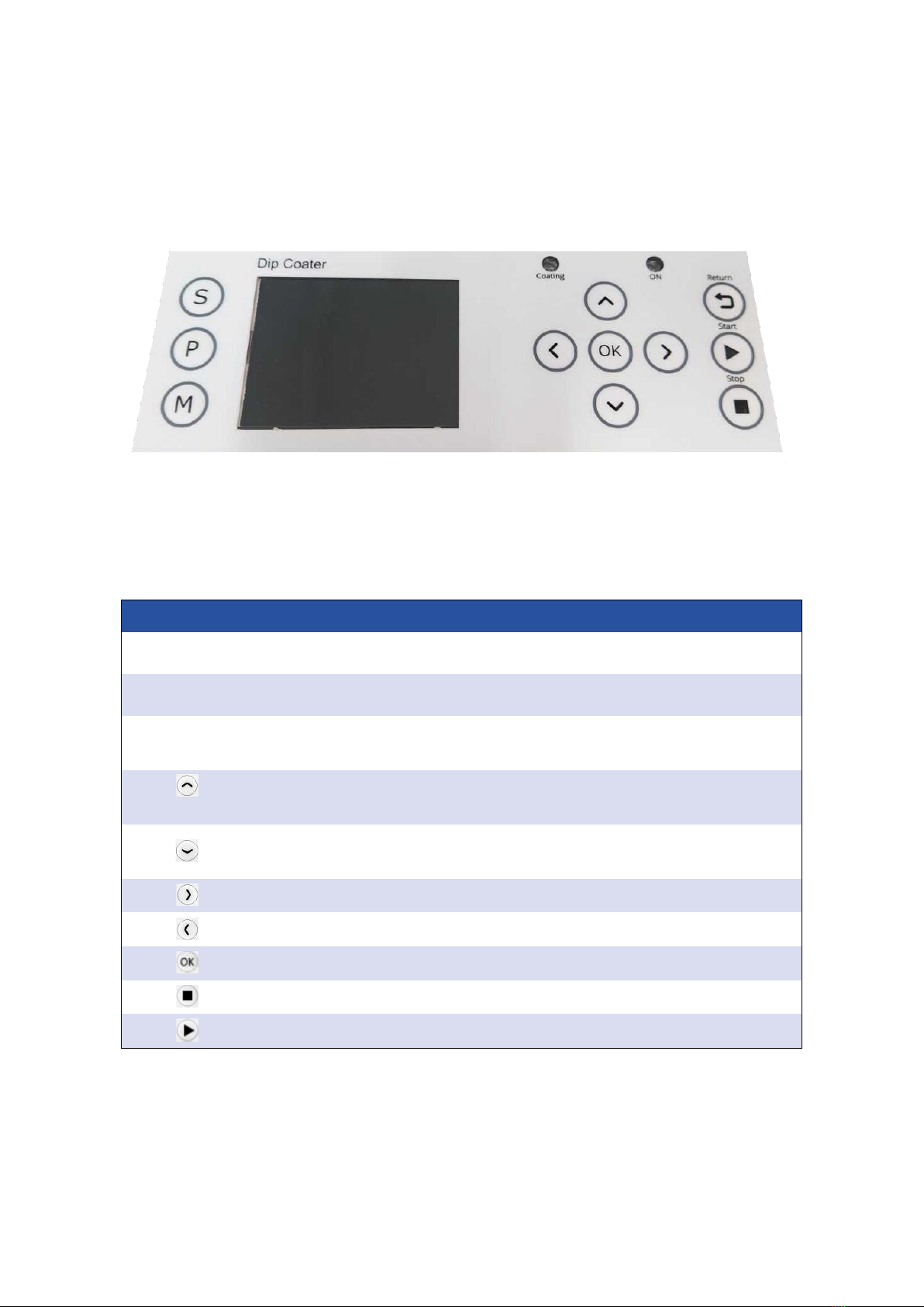
8.2 Dip Coater User Interface
Figure 8.2 shows the front panel of the Dip Coater, where the function of each of the keypad buttons
is explained in Table 8.1.
Figure 8.2. Dip Coater LCD screen and keypad.
Table 8.1. Operational buttons and their associated functions.
Button
Function
S (SETTINGS)
Enter the Settings menu where the solution height, substrate length, and
substrate position can be set. The units can also be altered here.
M (MANUAL)
Enter Manual mode where the immersion speed and withdrawal speed can
be set. The arm can be immersed and withdrawn manually.
P (PROGRAM)
Enter the Programming mode where saved programs can be selected and/or
edited.
Navigating ‘up’through menus; increasing selected values by 1; cycling
through options; moving the arm upwards (manual mode only)
Navigating ‘down’through menus; decreasing selected values by 1; cycling
through options; moving the arm downwards (manual mode only)
Navigating ‘right’through menus
Navigating ‘left’through menus
Press to select, edit, or accept changes
Stop the currently running program
Run the currently selected program

Ossila Dip Coater User Manual
ossila.com 17 Ossila Limited © 2017
8.3 Practical Operation
When using volatile solvents or hazardous solvents/materials, the instrument should be
placed within a fume hood or glovebox.
When using the dip coater, a general start-up procedure should be followed before beginning
to coat.
8.3.1 Positioning the Dipping Arm
1. Turn the unit on, press the ‘M’ button to enter the manual mode. Adjust the arm to its lowest
position.
2. Using the clamp height adjustment screw, raise the clamping arm so that it is around 10 mm
higher than the maximum length of the substrate you are coating.
3. Press return to raise the arm to the top.
8.3.2 Positioning the Reservoir and Dipping Arm
1. Place the solution reservoir on the base plate of the unit.
2. Centre the reservoir under the dipping arm.
3. The position of the dipping arm can be adjusted to be nearer or further away from the user
by loosening the arm adjustment screw.
4. Ensure that there is a distance of at least 1 cm from the edge of the baseplateof the dip coater.
8.3.3 Adjusting Clamp Strength
1. Pull back one half of the clamp and insert a substrate, being sure to provide support in case
the clamp strength is not yet high enough.
2. Let go of the substrate to check if the clamp can currently support its weight.
3. If the substrate begins to slip, tighten the clamp adjustment screw to increase the pressure
from the spring.
4. The screw should be tightened until the substrate is held securely in place.
5. If a delicate substrate is being used, you can reduce the clamp pressure by loosening the
adjustment screw.
8.3.4 Setting the Solution Height, Substrate Position, and Coating Length.
In the ‘settings’mode, you can:
1. Update the length that you wish to coat over.
2. The height of the solution relative to the ruler provided.
3. The position of the bottom of the mounted substrate relative to the ruler provided.

Ossila Dip Coater User Manual
ossila.com 18 Ossila Limited © 2017
8.4 Program Operation
8.4.1 Dip Coater Start Up
1. Switch ON (position ‘1’) the Ossila Dip Coater power switch. The screen below will be shown.
2. After the Ossila logo page, reset the arm to the ‘Home’position by pressing the OK button.
While the arm is moving to the ‘Home’position, the message below will be shown on the
screen.

Ossila Dip Coater User Manual
ossila.com 19 Ossila Limited © 2017
Once the system is at the ‘Home’position, the ‘Settings Mode’page will be prompted.

Ossila Dip Coater User Manual
ossila.com 20 Ossila Limited © 2017
8.4.2 ‘Settings’ Mode
1. To enter ‘Settings’mode, press the S button (located at the top left-hand side of the screen).
2. To edit the coating length value, press the OK button,then navigate between the digits by
pressing either the left or right button. To increase or decrease the value of the selected
digit, press the up or down button. Press OK again to exit the edit mode.
Note: The maximum travel distance of the system is 100mm. Any coating length and drying
gap values (refer to Step 7) should be within maximum travel distance. The coating length
will be auto-corrected if the added value is more than 100mm, and you will be alerted by a
warning message.
Other manuals for Dip Coater
1
Table of contents
Other Ossila Laboratory Equipment manuals


