OTT Parsivel User manual

English
Operating instructions
Present Weather Sensor
Parsivel

We reserve the right to make technical changes!

3
Table of contents
1 Scope of delivery 5
2 Part numbers 5
3 Parsivel Factory Settings 6
4 Safety instructions 7
5 Introduction 8
5.1 Functional principle 8
5.2 Connection Options for the Parsivel 9
6 Installing the Parsivel 10
6.1 Cable Selection 10
6.2 Wiring the Parsivel 11
6.3 Grounding the Parsivel 13
6.4 Installing the Parsivel 14
7 Connecting the Parsivel to a data logger 15
7.1 Connecting the Parsivel to the LogoSens Station Manager via RS-485 interface 15
7.2 Connecting the Parsivel to a Data logger via the SDI-12 Interface 17
7.3 Connecting the Parsivel to a Data Logger with Impulse/Status Input 21
8 Connecting the Parsivel to a PC 23
8.1 Connecting the Parsivel to Interface Converter RS-485/RS-232 (Accessories) 23
8.2 Connecting the Parsivel to the ADAM-4520 Converter RS-485/RS-232 (Accessories) 25
8.3 Connecting the Parsivel to Interface Converter RS-485/USB (Accessories) 26
8.4 Connecting the Parsivel to any RS-485 Interface Converter 27
8.5 Connecting the Parsivel for configuration via the Service-Tool to a PC 27
9 Connecting the Parsivel to a Power Supply (Accessory) 29
10 Heating the Parsivel sensor heads 30
11 Operating Parsivel with a Terminal software 31
11.1 Set up communications between the Parsivel and the terminal program 31
11.2 Measured value numbers 32
11.3 Defining the formatting string 33
11.4 OTT telegram 33
11.5 Updating Parsivel Firmware 34
12 Maintenance 36
12.1 Cleaning the laser’s protective glass 36
12.2 Keeping the light pathway open 36
12.3 Cleaning the splash protector 36
13 Functional disruptions and remedies 38
11.1 Parsivel does not start 38
11.2 Disruptions due to convection and vibrations 38
14 Technical data 39

4
Appendix A: CS Command Set 40
Appendix B: Classification of precipitation types 43
B.1 Class limits 43
Appendix C: Characterization of precipitation type by precipitation codes 45
C.1 Precipitation code according to SYNOP 45
C.2 Precipitation code according to the NWS and METAR/SPECI w’w’, Table 4678 46
Declaration of Conformity 47

5
1 Scope of Delivery
䊳Parsivel – 1 Parsivel measurement head is an optical sensor with 30 mm wide and
180 mm long light strip in the tunnel housing
– 1 Installation set with
1 screwed terminal strip 7 slots
7 wire end sleeves
1 grounding cable lug
1 flat washer
6 M 8 X 16 grub screws
7 M 8 X 25 grub screws
1 M8 hex nut
2 lock washers
1 Allen key - 4 mm
1 Allen key - 2.5 mm
– 1 Parsivel software ASDO Basic
– 1 set of operating instructions
2 Part Numbers
䊳Parsivel Parsivel 70.200.005.9.0
– with 2 special spray protection units
– with installation set
– with Parsivel software ASDO Basic
䊳Accessories Interface converter
– RS-485 / USB 97.961.091.9.5
– RS-485 / RS-232 97.970.041.9.5
Power supply Parsivel
IP 20, without mast support 97.850.011.9.5
IP 67, with mast support 97.850.012.9.5
Connecting cable Parsivel/Power supply IP 65 70.200.107.4.2
Connecting cable Parsivel/Electronic cabinet max. 100 m 97.000.038.9.5
Parsivel software ASDO for PC (full version) 56.551.001.9.7
LogoSens RS-485 termination module 70.200.803.9.5
Service Tool
consisting of
– interface converter RS-485/USB 97.970.044.9.5
– assembling cable for the interface converter 70.200.106.4.2
䊳Replacement Spray protection (1 piece) 70.200.405.3.1
parts

3 Parsivel Factory Settings
Parsivel is a flexibly configurable device concerning terminal assignment, interface
parameters and heating settings, and is supplied with the following factory set-
tings:
Operating mode: RS-485 2-wire
Baud rate RS-485: 19,200 baud
RS-485 bus mode: deactivated
Bus address RS-485: 0
SDI-12 interface: deactivated
SDI-12 bus address: 0
Impulse output 0.1 mm: activated
Status: solid=0, liquid=1
Heating mode: off
Data telegram: OTT telegram (see Chapter 11.4)
Measurement interval: 30 s
The parameters can be set using Parsivel software ASDO or using a terminal soft-
ware package. Information on the setting of these parameters is available in
Appendix A, “CS Command Set” or in the operating instructions “Parsivel Soft-
ware ASDO”.
6

4 Safety Instructions
䊳These operating instructions contain basic instructions that must be followed
during installation, operation and maintenance. Therefore, it is absolutely nec-
essary that they be read by the assembler and by the responsible technical per-
sonnel/operator prior to installation and startup!
䊳These operating instructions must be accessible at the point of use of the mea-
surement device!
䊳Personnel responsible for installation, operation and maintenance must have
the appropriate qualifications for this work! Responsibilities, competency and
the monitoring of personnel must be closely controlled by the owner.
If personnel do not have the required knowledge, it must be provided through
training and instruction. If necessary, OTT MESSTECHNIK can provided this
service on a contractual basis for the owner.
䊳Non-adherence to these safety instructions can have dangerous consequences
for persons as well as for the measurement device!
䊳Non-adherence to these safety instructions can result in the loss of any indem-
nity claims!
䊳Please adhere to the safety instructions listed in these operating instructions,
to all existing national accident prevention regulations and to any internal
work, operating and safety rules as set forth by the owner!
䊳The operating safety of the delivered measuring device is only guaranteed
when it is used properly! Retrofitting or changing the measuring device is only
allowed if authorized by the manufacturer.
䊳To ensure safety, buy only original replacement parts and accessories autho-
rized by the manufacturer. Use of other parts can void liability for any conse-
quences arising therefrom!
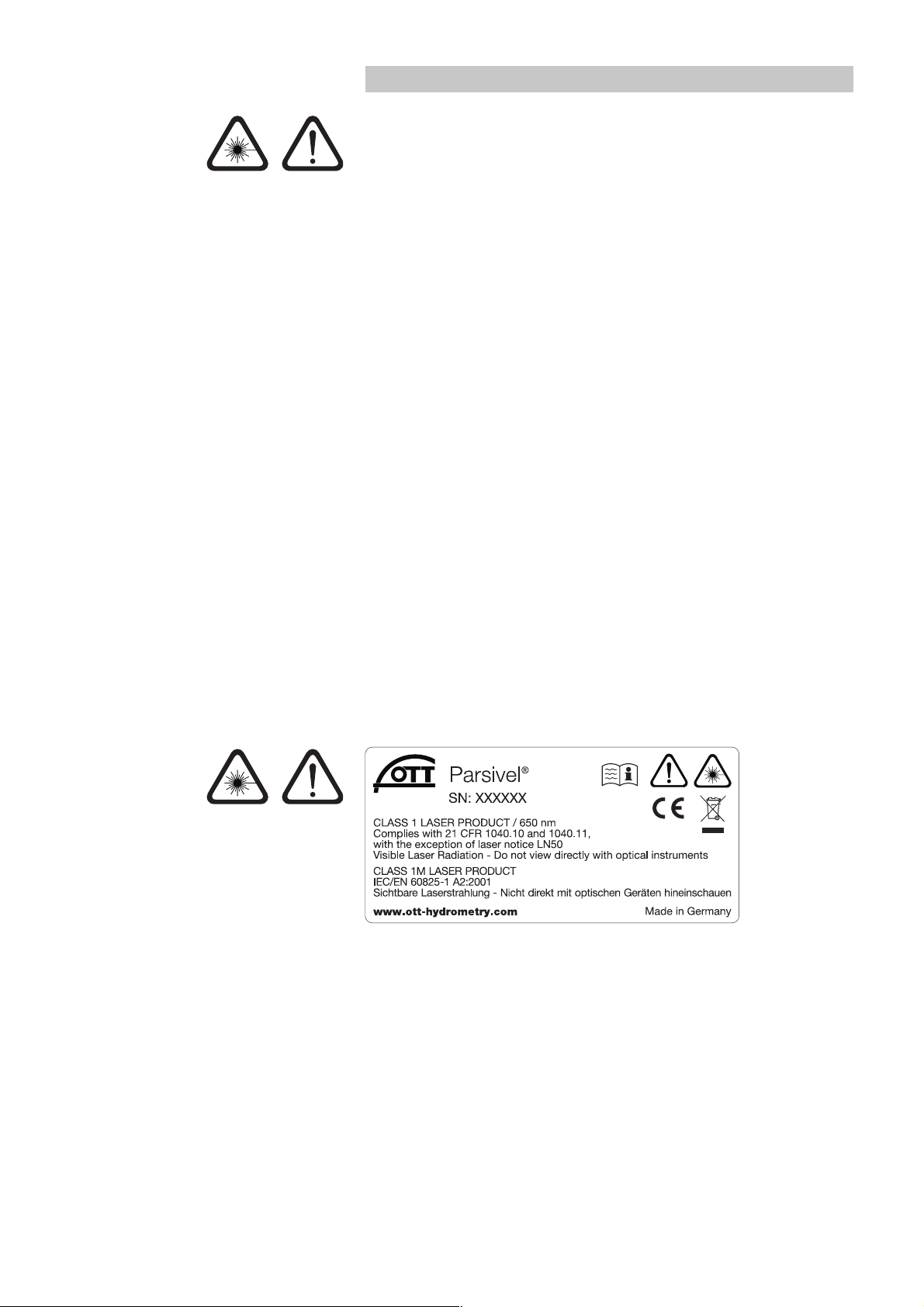
䊳The Parsivel contains an embedded class 2 laser device and is a class 1/1M
laser product which complies with IEC/EN 60825-1 A2:2001 (EU) / 21CFR
1040.10 and 1040.11 (USA) with the exception of laser notice LN50.
Wavelength: 650 nm; output: max. 3 mW.
䊳Do not open the instrument and remove any barrier that would expose to laser
beam of embedded laser class 2 device!
䊳Do not stare into the beam or view directly with optical instruments!
䊳Optical light barriers must never be removed except by OTT Service personnel.
When barriers are removed, power to the Parsivel must be disconneted.
7

5 Introduction
Parsivel is a laser-based optical system for complete and reliable measurement
of all types of precipitation. The size range of measurable liquid precipitation par-
ticles is from 0.2 … 5 mm, for solid precipitation particles it is from
0.2 … 25 mm. In the process, precipitation particles can have a velocity of from
0.2 … 20 m/s. The precipitation particles are categorized as follows:
䊳Drizzle
䊳Drizzle with rain
䊳Rain
䊳Rain, drizzle with snow
䊳Snow
䊳Snow grains
䊳Freezing rain
䊳Hail
The precipitation measurements are carried out using a special sensor head that
was developed for this particular purpose. It detects precipitation optically. The
data thus determined are processed and stored by a fast digital signal processor.
Parsivel issues one data telegram every 30 seconds.
5.1 Functional principle
The theory behind Parsivel is a laser sensor that produces a horizontal strip of
light. The emitter and the receiver are integrated into a single protective housing.
Measurement of particle size
If there are no particles in the laser beam, the maximum voltage is output at the
receiver. Precipitation particles passing through the laser beam block off a portion
of the beam corresponding to their diameter, thus reducing the output voltage; this
determines the particle size.
Measurement of particle speed
To determine the particle speed, the duration of the signal is measured. A signal
begins as soon as a precipitation particle enters the light strip and ends when it
has completely left the light strip.
Transmitter Receiver
Precipitation particle
Laser beam
Fig. 1: Functional principle of the Parsivel.
8

The following parameters can be derived from these two determined quantities:
䊳Size spectrum
䊳Type of precipitation
䊳Kinetic energy
䊳Intensity of the precipitation
䊳Radar reflectivity
䊳Visibility
The spray protection attached to the sensor head prevents precipitation particles
from deflecting off the housing, falling into the laser beam and thus falsifying the
measurements.
5.2 Connection Options for the Parsivel
The Parsivel can be connected to various devices as shown in the illustration
below. Refer to the respective chapters in this regard.
Parsivel
Pipe
H = Total height
Disdrometer
general: 1 m
Present Weather
Sensor Parsivel: 2 m
Cable
max. 300 m
(RS-485)
Cable
max. 300 m
(RS-485)
Cable
max. 300 m
(RS-485)
Cable
max. 70 m
SDI-12
Interface
converter
Interface
converter
RS-485
LogoSens 2
Termination module
LogoSens
®
2
– ASDO Basic
Storage without
precipitation
spectrograph
– ASDO full version
Storage with
precipitation
spectrograph
– Hydras 3
online online
RS-232/USB RS-232/USB
RS-485/
2-wire
SDI-12
data logger
Power supply
Signal outputs:
RS-485
SDI-12
Impulse
Status
Impulse
+ Status
data logger
SDI-12
cable length
see
chap. 6.1
power supply
Chapter 8 Chapter 8 Chapter 7.1 Chapter 7.2 Chapter 7.3 Chapter 9
9

6 Installing the Parsivel
Please follow Safty Instructions (see chapter 4) when installing
the Parsivel!
It is of critical importance to the quality of the measurements that the setup loca-
tion be selected carefully. Here, wind and vibrations must be minimized (see chap-
ter 13.2 „Disruptions due to Convection and Vibrations“). If the protection against
these influences is not sufficient, virtual drops can be detected.
Prerequisites
The Parsivel is mounted on a pipe. The pipe must have the following specifications:
䊳Pipe diameter 50 … 62 mm
䊳Pipe consists of an electrically conducting material and is grounded
䊳
The concrete foundation of the pipe must have minimum dimensions of
35 x 35 x 80 cm (L x W x H)
.
Before the Parsivel can be fastened to the standpipe, the data transmission cable
and power supply must be installed.
6.1 Cable Selection
Data Transmission Cable
The Parsivel has the following signal outputs:
䊳RS-485
䊳SDI-12
䊳Impulse output
䊳Status output
We recommend that the data transmission cable has the following characteristics:
䊳Twisted-pair cable
䊳Usage length for transfer via the RS-485 interface, max. 300 m
䊳Usage length for transfer via the SDI-12 interface, max. 70 m
䊳Cable cross section ≥0.5 mm2
Power supply cable
For the 24 V power supply, we recommend a cable with a maximum resistance of
2Ω. The maximum voltage drop at 2 A is 4 V. The cable length depends on the
cable cross sectional area:
Cable cross section max cable length
0.25 mm214 m
0.5 mm228 m
0.75 mm242 m
1.0 mm256 m
1.5 mm284 m
2.5 mm2140 m
4.0 mm2225 m
10

6.2 Wiring the Parsivel
Proceed as follows to wire the Parsivel:
䡵Pull the existing connection cables from the external electronic unit upward
through the standpipe.
䡵Remove the bottom cover of the sensor head, attached to the rear of which is
the laser warning label. To do so, remove the two hex screws from the bottom
cover using the 2.5 mm Hex key supplied.
䡵Run the connecting cables from below through the cable gland (see Fig. 7) of
the Parsivel and then through the interior of the Parsivel to the opened sensor
head.
䡵Connect the cables to the 7-slot screw terminal provided (installation set) accor-
ding to the configuration of the Parsivel as described in Figures 2 through 4.
Parsivel
Power supply GND
Power supply 11 … 36 V DC
RS-485 4-wire B (+) IN
RS-485 4-wire A (–) IN
RS-485 4-wire B (+) Out
RS-485 4-wire A (–) Out
123 4567
Fig. 3: Connection Assignment
for a 4-wire connection
with RS-485 transfer.
Parsivel
Power supply GND
Power supply 11 … 36 V DC
RS-485 2-wire B (+)
RS-485 2-wire A (–)
Digital Status
Digital Impulse
123 4567
Digital GND
Fig. 2: Wiring assignment
for a 2-wire connection
with RS-485- and pulse-output.
The SDI-12 connection is turned off.
This terminal assignment is
for standard use.
11

䡵Plug the screwed terminal strip onto the sensor head as shown in Figure 5.
䡵Re-fasten the bottom cover of the sensor head using the two Allen screws.
䡵Tighten the screwed cable connection.
䡵Connect the shielding to the corresponding power supply.
Fig. 5: Plug the screw terminal strip
onto the Parsivel sensor head.
Parsivel
Power supply GND
Power supply 11 … 36 V DC
RS-485 2-wire B (+)
RS-485 2-wire A (–)
SDI-12 Data
Digital Impulse
Digital GND/SDI-12 GND
123 4567
Fig. 4: Connection Assignment
for a 2-wire connection with
RS-485 of SDI-12 transfer.
12

6.3 Grounding the Parsivel
To ground the Parsivel, you will need the following parts from the installation set
provided:
䊳1 hex key 4 mm
䊳1 M 8 X 25 grub screw
䊳2 lock washers
䊳1 cable lug
䊳1 flat washer
䊳1 M8 hex nut
Also, you will need a grounding cable with a wire cross section of 16 mm2.
In order to ground the Parsivel, proceed as follows:
䡵Rotate the grub screw using the hex key from inside into the grounding hole
(see Fig. 6) until the grub screw is flush with the inner wall inside the socket.
䡵Place the lock washers, cable lug and washer as shown in Fig. 6 onto the grub
screw from the outside.
䡵Likewise, screw the hex nut from outside onto the grub screw and tighten it.
Hold the grub screw from the inside using the hex key while doing so so that it
does not rotate during tightening.
䡵Loosen the two copper screws of the cable lug by rotating them a few turns.
䡵Remove the insulation from one end of the grounding cable approximately
2 cm.
䡵Insert the un-insulated end of the grounding cable between the two plates of
the cable lug and re-tighten the two copper screws. The other end of the cable
must be properly grounded near the Parsivel.
Grub screw
Copper screws
Lock washers
flat washer
Hex nut
Cable lug
Hex key
Grounding hole
Fig. 6: Grounding the Parsivel.
The individual parts to fasten the
cable lug are included in the installation set.
13

6.4 Installing the Parsivel
Proceed as follows to install the Parsivel:
䡵Slide the attached Parsivel downward onto the pipe.
䡵Orient the Parsivel such that the laser beam is perpendicular to the local main
wind direction.
䡵Evenly tighten the 6 M 8 x 16 grub screws, or M 8 x 25 depending on the dia-
meter of the pipe stand, using the 4 mm hex key provided (installation set) so
that the sensor head is horizontal as much as possible.
1
2
Cable gland
Fig. 7: Installing the Parsivel.
14

7 Connecting the Parsivel to a data logger
The Parsivel can be connected to the following data loggers:
䊳LogoSens with an RS-485 interface
䊳LogoSens with an SDI-12 interface
䊳Any data logger with an SDI-12 interface
䊳Parallel operation of a data logger with SDI-12 interface and a PC (RS-485)
䊳Data logger with impulse or status input
7.1 Connecting the Parsivel to the LogoSens Station Manager via
RS-485 interface
The measured values determined by the Parsivel can be queried by the LogoSens
station manager and stored.
Connect the Parsivel via the RS-485 interface to the LogoSens as shown in figure 8.
Configuring the LogoSens Station Manager for RS-485
communication
To be able to query and store the data from the Parsivel using the LogoSens,
a configuration must be set up in the LogoSens. Figure 9 shows an example Logo-
Sens configuration for communication via the RS-485 interface. See operating
instructions of “LogoSens Station Manager” for more on this. Make sure that the
measurement cycle set up in all Parsivel channels is provided with the same value.
Parsivel
1234567
R = 120 Ω
from 20 m
of cable length
LogoSens
A … R
GND
RS-485 B +
+
11 … 36 V DC
+VBat
–12 V
GND
+ 5 V
RS-485 A –
–GND
LogoSens
T
4312
Power supply
11 … 36 V DC
LogoSens Termination module
(accessories)
Fig. 8: Connecting the Parsivel to the
LogoSens via the RS-485 interface.
15

Fig. 9: LogoSens Configuration Example
when connecting to an RS-485 interface.
16

7.2 Connecting the Parsivel to a Data logger via the
SDI-12 Interface
If a data logger is used that is connected via an SDI-12 interface, the data logger
functions as a master, and specifies the measurement time and sample interval of
the Parsivel. The measurement time must be ≥1 min in this case in order for the
Parsivel to collect sufficient data during winter operation as well to allow for the
precise assignment of precipitation type.
To make the Parsivel capable of communicating for an SDI-12 interface, the Parsi-
vel must first be connected to a PC via the RS-485 interface. The SDI-12 interface
can be switched to active through the Parsivel application software ASDO or
using a terminal program and the command “CS/S/E/1<CR>“ (see operating
instructions for the Parsivel application software ASDO and Chapter 11 “Parsivel
Operated through Terminal Software“).
Warning: The failure of the SDI-12 master will result in losing the connectivity in
parallel operation with ASDO!
SDI-12 Data Formats
Value 0: Rain intensity [mm/h]
Value 1: Rain amount accumulated [mm]
Value 2: Weather code according to SYNOP wawatable 4680
Value 3: Radar reflectivity [dBz]
Value 4: MOR visibility during precipitation [m]
Value 5: Sample interval [s]
Value 6: Signal amplitude of the laser strip [1]
Value 7: Number of detected particles [1]
Connecting the Parsivel to any Data logger via the SDI-12 Interface
Connect the Parsivel to any data logger as shown in Fig. 10 via the SDI-12 inter-
face:
Parsivel
1234567
GND
11 … 36 V DC
GND
SDI-12 Bus
Power supply
11 … 36 V DC
Data logger
Fig. 10: Connect the Parsivel to any data
logger via the RS-12 interface.
17

Connecting the Parsivel to the LogoSens Station Manager via the
SDI-12 Interface
Connect the Parsivel to the LogoSens via the SDI-12 interface as shown in Fig. 11:
Configuring the LogoSens Station Manager for SDI-12
communication
In order to call up and store data from the Parsivel using the LogoSens, a configu-
ration must be created in the LogoSens. Figure 12 shows an example LogoSens
configuration for communication via the SDI-12 interface. See operating instruc-
tions of “LogoSens Station Manager” for more on this. Make sure that the measu-
rement cycle set up in all Parsivel channels is provided with the same value and
that in no channel of the LogoSens configuration an instantaneous vaue is defined,
otherwise erroneous measurements are possible.
Parsivel
1234567
GND
11 … 36 V DC
SDI-12 GND
SDI-12 Data
LogoSens
A … R
4312
LogoSens
T
4312
Power supply
11 … 36 V DC
Fig. 11: Connecting the Parsivel to the
LogoSens via the RS-12 interface.
18

Fig. 12: LogoSens Configuration Example
when connecting to an SDI-12 interface.
19

Connecting the Parsivel in parallel to an SDI-12 data logger and
to a PC
You have the option of reading out the measurement data from Parsivel in parallel
via an SDI-12 data logger and via the Parsivel software ASDO on a PC (see the
operating instructions to Parsivel’s application software ASDO). The SDI-12 data
logger specifies the time base for this.
Note:
The sample interval in the Parsivel software ASDO must be set to the sample inter-
val of the SDI-12 data logger (see the operating instructions for the Parsivel appli-
cation software ASDO).
Warning: The failure of the SDI-12 master will result in losing the connectivity in
parallel operation with ASDO!
In order to operate the Parsivel simultaneously with the Parsivel software ASDO
and an SDI-12 data logger, proceed as follows:
䡵Connect the Parsivel to the RS-485/USB interface converter via the 2-wire
connection.
䡵Connect the LogoSens to the Parsivel via the SDI-12 interface.
Parsivel
1234567
GND
11 … 36 V DC
GND
SDI-12 Data
– a
+ b
Power supply
11 … 36 V DC
Data
logger
Interface
converter
Fig. 13: Parallel connection of SDI-12 data
logger and Parsivel software ASDO.
20
Table of contents
Other OTT Accessories manuals
Popular Accessories manuals by other brands

CMP
CMP DEL AOP-S INSTALLATION INSTRUCTIONS & PRODUCT MANUAL

Siemens
Siemens QAM2151.040/MO Basic documentation

Dometic
Dometic Power Awning Pro 3316554 Series Installation & operating instructions

Philips
Philips SAC2505W Specifications

IDW
IDW G-Series instruction manual

ETC
ETC Sohrana Dual Tech installation guide

Baader Planetarium
Baader Planetarium HYPERION Universal Zoom MARK IV instruction manual

AKCP
AKCP Thermal Map manual

X-lander
X-lander Around the World Move Instructions for use

Optima Scale
Optima Scale OP-902 user manual

Perfect Choice
Perfect Choice PC-044475 user guide

Spectris
Spectris Particle Measuring Systems IsoAir 310P Operation manual