Otterbine/Barebo Concept3 User manual

1
Water Works
With Otterbine
CONCEPT3
Owner's Manual
A Guide to More Dependable
WaterQualityManagement
With Otterbine Barebo Inc.'s
1-5 Horsepower Surface Spray
AeratingFountain

2
Welcome Aboard!
Welcome to the growing family of people who depend on
aerating fountains for better water quality control and
aesthetic improvement. Otterbine Barebo, Inc. moves its
aerating fountain line into the next century with a revolu-
tionary platform. This design offers an industry first five-
year warranty with virtually no maintenance, reduced float
visibility,andinterchangeablespraypatterns.AllOtterbine
products are safety tested and approved by ETL, ETL-C
and CE
Water Quality Specialists
Barebo, Inc. is a team of scientists, engineers, and crafts
persons who specialize in efforts to improve water quality.
Otterbine aerating fountains are built at Barebo, Inc.'s
25,000 square foot factory in Emmaus, Pennsylvania. Each
step in assembly is followed by a quality assurance check
tomaintainhighquality.
The Concept3line of Otterbine aerators, made of stainless
steel and high tech engineering plastics, reflects the results
of aerator research and development programs that started
in 1956, plus the experience gained through thousands of
installations on commercial fish farms, golf courses, parks,
andarchitecturalapplications.
Follow the Guidelines
You'llfindguidelinesforinstalling,operating,andmain-
taining your aerating fountain in the following pages. We
strongly recommend that you read, understand, and apply
these guidelines. They will help you get better perfor-
mance and dependability from your Otterbine aerating
fountain.
SUNBURST3
GEMINI3
PHOENIX3
TRI-STAR3ROCKET3
COMET3
CONSTELLATION3
SATURN3GENESIS3

3
Table of Contents:
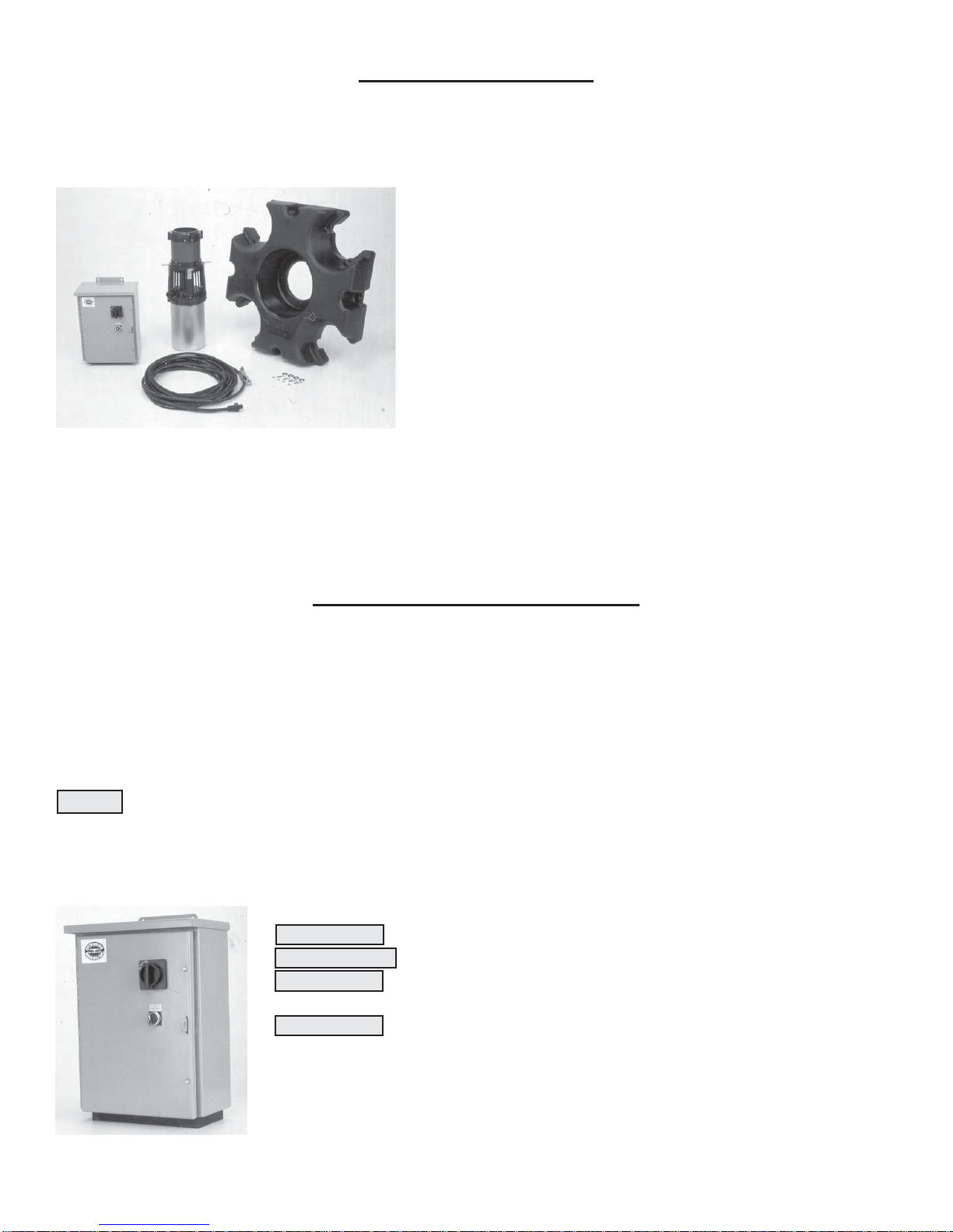
Aerator Equipment ........................................................................................................................ 4
Electrical/PCCInstallation ............................................................................................................. 4-5
Timer Operation............................................................................................................................. 5
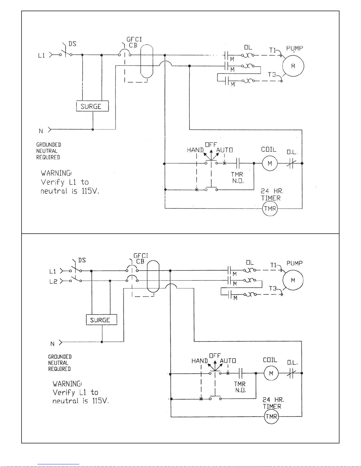
Power Control Center Schematics ................................................................................................. 6-8
Aerator Placement ......................................................................................................................... 9
MountingtheFloat/SupplementalFloattotheUnit ............................................................................ 10
Comet Stabilizer Plates Mounting ................................................................................................. 11
PhysicalInstallation........................................................................................................................ 12-13
Mooring ......................................................................................................................................... 14
Anchoring ...................................................................................................................................... 15
ElectricalTests............................................................................................................................... 16
Open Throat Pump Chambers Parts List ....................................................................................... 17
SunburstPumpChamber/AssemblyInstructions ........................................................................... 18
GeminiPumpChamber/AssemblyInstructions .............................................................................. 19
SaturnPumpChamber/Assembly Instructions ............................................................................... 20
Decorative Pump Chambers Parts List .......................................................................................... 21
RocketPumpChamber/AssemblyInstructions.............................................................................. 22
PhoenixPumpChamber/AssemblyInstructions............................................................................. 23
Tri-StarPumpChamber/AssemblyInstructions ................................................................................ 24
ConstellationPumpChamber/AssemblyInstructions ......................................................................... 25
CometPumpChamber/AssemblyInstructions .................................................................................. 26
GenesisPumpChamber/AssemblyInstructions................................................................................. 27
EquinoxPumpChamber/AssemblyInstructions ................................................................................ 28
PowerUnitPartsList....................................................................................................................... 29
PowerUnitDiagram ........................................................................................................................ 30
ScreenInstallation............................................................................................................................ 31
TroubleShooting ............................................................................................................................. 32
TechnicalData-Domestic ............................................................................................................... 33-34
TechnicalData-International........................................................................................................... 35-36
MaximumCableLengths ................................................................................................................. 37
Maintenance .................................................................................................................................... 37
WinterizationandSpecialWarnings.................................................................................................. 38
OtterbineWarranty.......................................................................................................................... 39
Revised11/06/2008
WARNING: PHYSICALLY disconnect the unit and lights from their
electrical source before entering, wading or swimming in the water in
which they are installed. Only factory approved power cord is to be
used. Do not splice or repair the cord, replacement is necessary if
damage occurs.

Aerator Equipment
Unpack and inspect your aerator, report any damage to the carrier that delivered your aerator. Make sure you
havereceived the following: 1. Unit - you will find a label located on the housing of the unit.
Check the label to make sure you have received the correct
horsepower and voltage aerator.
2. Float - including hardware kit to mount float to the unit or
extra hardware kit if float already mounted to unit
3. Power Control Center - you will find a label inside of the
Power Control Center door. This label lists the voltage and
horsepower of the control center. Verify that the aerator and
control center are the same horsepower and voltage.
4. Power Cable Assembly - verify that you have received the
correct length.
5. Warranty Registration Card - make sure to fill in your Otterbine warranty registration card and send it
back to the factory so that we can send you our bi-annual customer newsletter, which will keep you up to date
on all the latest aeration news. WARRANTY IS VOID UNLESS CARD IS RETURNED.
Electrical/PCC Installation
This weather resistant NEMA 3R Power Control Center comes complete with a twenty-four hour on/off timer,
magnetic contactor with overload relay, surge arrestor, disconnect, overcurrent protection, HOA switch, and
ground fault protection (where applicable). All internal connections are pre-wired. All electrical specifications
are located on the door of the Otterbine Power Control Center. Otterbine recommends that all ELECTRICAL
WORK BE DONE BY A QUALIFIED, LICENSED ELECTRICIAN. Make sure that all electrical work
conforms with local, state and national electrical codes.
NOTE: Otterbine suggests coordinating electrical installation with physical installation. The electrician will
need to be on hand for a one minute dry-run test of the unit and will also need to check the running amperage
after installation. These electrical tests are a crucial part of the installation process and should not be
ignored. A. Install the Otterbine Power Control Center as close to the pond as possible.
CAUTION: The Power Control Center should not be accessible from the water.
ATTENTION: la loite de control ne doit pas être accessible de l'eau.
WARNING: Screw connections may loosen during shipping, verify that all screw
connections are tight before energizing PCC.
CAUTION: Otterbine recommends that the PCC not be mounted in direct sun
light when installed outdoors.
B. Your Otterbine Power Control Center can be mounted indoors or outdoors.
1. When mounting outdoors Otterbine suggests that you use a piece of exterior
plywood and sturdy 4 x 4 post(s).
2. When mounting indoors the PCC can be mounted directly to the wall.
4

C. Attachincomingpowertothetopofthedisconnect,neutraltotheneutralbar(neededin115V1Ph60Hz,
230V 1Ph 60Hz, and 230V 3Ph 60Hz PCC's; L1 to neutral must always be 115 volts) and earth ground to the
ground lug. Otterbine recommends that all exterior incoming power cable and exterior aerator cable be encased
inconduit.
D. Attachaeratorpowercabletothecontactpointsontheoverloadrelaywiththegreengroundwiretothe
groundluginthePowerControlCenter. MakesuretoalwaysuseOtterbineaeratorcable. IfOtterbineaerator
cableisnotused,theWARRANTYISVOID.
IMPORTANTNOTES:
1.OnlyOtterbineBarebo,Inc.factoryapprovedpowercordistobeusedfromthePCCtotheaerationunitwithno
junctionboxesorsplices.Donotusepowercordgagesandlengthsotherthanthosespecifiedonp.37ofthismanual.
2.EachcableshouldbeinitsownconduittoavoidnuisancetrippingoftheGFCIdevice.
3.Wiringschematicsarelocatedonthefollowingpages.Pleasenoteonall460VunitsEPD/GFCI(EquipmentProtec-
tionDevice/GroundFaultCircuitInterrupter)isanoptionalaccessory.
WARNING: AllOtterbinesubmersibleaerationsystemsmustbeinstalledinconformancewithalllocal,stateand
nationalelectricalcodes. OtterbineaerationsystemsrequiretheuseofGFCIforsafeoperation. Iftheproperground-
ingandGFCIprotectionarenotused,seriousorFATALelectricalshockmayoccur.
ADVERTISSEMENT: Otterbine®fortementsuggestequ'aupanneaudebranchementélectriqueuninterupteur
aveccontroldedefautdemassesoitinstallé,oulespersonnessetrouberaiprésdel'eau.
SATELLITECONTROLLERS: Customcontrolpanelsareavailableasanoptionforcustomersusing
computerizedirrigationcontrollers. Thesepanelswillinterfacewiththecomputerandallowyoutorunyourunits(s)/
lights(s)remotely. SeeyourlocalOtterbinedistributororcallOtterbinedirectlyformoreinformation.
WARNING: Afullthreephasepowersupplyisrecommendedforallthreephasemotors,consistingofthreeindi-
vidualtransformersoronethreephasetransformer.Socalled"open"deltaconnectionsarenottruethreephasepower
suppliesandarelikelytocauseproblemsofcurrentunbalance.Opendeltaconfigurationsandphaseconvertersoften
sufferfromlineunbalancewhichcancausepoormotorperformance,nuisancetrippingorprematuremotorfailure.
WARRANTYISVOIDifafactoryauthorizedphaseconverterisnotused.
EarthGroundSymbol(usedinPCC)
GrasslinTimer
Timer Operation
GrasslinTimer60Hz,P/N:31-0070
GrasslinTimer50Hz,P/N:31-0180
1. Pushin(towardscenter)allofthetripperpinsonthetimerdial.
2. Pulloutallofthetripperpinsonthedialthatarebetweenthetimesyouwanttheunit
torun. Example: Ifyouwanttheunitonfrom7:00AM-5:00PM,youwouldthenpull
outallofthetripperpins betweenthose times. Whenthedialrotatestoatripperpinthat
isin,itwillturnoff.
3. Turn the dial clockwise to set the time of day. Close the panel and apply power.
Incaseofpowerfailure,resettimer.
5

115 Volt 1 Phase 60 Hertz Schematic
208-230 Volt 1 Phase 60 Hertz Schematic
6

208-230 Volt 3 Phase 60 Hertz Schematic
460 Volt 3 Phase 60 Hertz Schematic
7

220 Volt 1 Phase 50 Hertz Schematic
380/415 Volt 3 Phase 50 Hertz Schematic
8

Aerator Placement
Aerator Placement -Placement is crucial to how quickly and efficiently your Otterbine aerator is able to clean
your pond. The following diagram shows the most common ponds and the most effective aerator placement in
these ponds.
9

Mounting the Float to the Unit (Figure 1)
NOTE: Failureto completeassemblyas directedcould result indamage totheunit.
*ForaGenesisPumpChamber, the floatmustbemountedbeforetheGenesis ThroatAssemblycanbe
mountedtotheunit(Seepage27forGenesisPumpChamber).
*For5HP"OpenThroat"Units(Sunburst,Gemini,Saturn),mounttheSupplementalFloattotheMainFloat
beforeinstallingonUnit(SeeSupplementalFloatInstructionsbelow)
A.Theunitwillbereceivedwiththepumpingchamberalreadymounted.MountSupplementalFloatfirst,ifapplicable.
Standtheunituprightandplacethefloatontoitsotheholesinthefloatlineupwiththeholesinthemountingbrackets.
B. Place a fender washer onto a hex bolt and insert into one of the four holes in the float making sure it also goes
through the hole in the mouting bracket on the unit. Repeat this for the three remaining holes.
C. Place a flat washer and a nylon locknut onto each of the four hex bolts from Step B. Tighten each nylon
locknut. CAUTION: Do not overtighten, may cause damage to the float and/or pump chamber.
Item No Description Qty Part Number
Not Shown Float Mounting Hardware Kit 1 12-0071
1 S/S Hex Bolt, M8 x 45mm 5 22-0022
2 S/S Nylon Locknut, M8 5 26-0007
3 S/S Fender Washer, M8 (5/16") 5 28-0008
4 S/S Flat Washer, M8 (5/16") 5 28-0018
5 Ty-Rap (used to secure power cable) 3 GP5008
NOTE: Quantities include extra hardware.
Figure1
13
2
4
FloatPartNumbers/Color
42-0018Black
42-0027Granite
42-0028Sandstone
SupplementalFloatInstructions
*IftheSupplementalFloatisalreadymountedtotheMain
Float,continuewithStepAabove.
1. Place Main Float on the ground face down.
2. Place the Supplemental Float on the Main Float as shown in
the photo below.
3. Ty-Rap the floats together in four places (1 in each pocket).
4. Go to Step A above to continue float mounting.
SupplementalFloat
(p/n42-0048)
MainFloat
LargeTy-Rap
(p/n46-0051)
10

Comet Stabilizer Plates Mounting (Figure 1a)
NOTE: These instructions are for the Comet spray pattern ONLY. If you have any other spray pat-
tern continue with Physical Installation on page 12. The stabilizer plates steady the spray pattern and
prevent it from rocking back and forth.
A. Mount each of the four stabilizer plates to the top side of a bracket using a hex bolt, a fender washer, and a
nylon locknut as shown in Figure 1a.
B. Mount each of the four stabilizer plate assemblies from Step A to the top side of an outer hole in the float
using an eyebolt, a fender washer, and a nylon locknut as shown in Figure 1a. CAUTION: Do not overtighten,
may cause damage to the float.
C. The eyebolts are to be used to moor the unit into place.
ItemNo Description Qty Part Number
1 Stabilizer Plate Bracket, S/S 4 40-0115
2 Stabilizer Plate 4 41-0127
3 S/S Eyebolt, 5/16"-18 x 1-3/8" Fully Threaded 4 22-0027
4 S/S Fender Washer, 5/16" 8 28-0008
5 S/S Nylon Locknut, 5/16"-18 8 GP1208
6 S/S Hex Bolt, 5/16"-18 x 3/4" 4 106-302
Comet Stabilizer Plates Kit, P/N 12-0097
Figure 1a
2
1
3
4
5
4
56
11

Physical Installation
WARNING: DISCONNECTPOWERBEFOREINSTALLING,REMOVING,ORSERVICINGUNIT
Priortoinstallationpleasemeasureyourwaterdepth. All1-5HPConcept3Otterbineaeratorsrequireatleast
30"/75cm(40"/100cmifunithaslights)ofwaterdepthtorunproperly. Ifthewateristooshallow,digoutaportion
ofthepondbottomdirectlyundertheaerator. Ifhighwavesorlargefluctuationsinwaterdepthoccur,itmaybe
necessarytoallowformoredepth.
NOTE: Power must be applied to unit immediately after placement into the water and operated continuously
for the forty-eight (48) hour duration. Do not allow any AFL aerator to be placed into the water until the unit is
fullyoperational.
NOTES:
1.5HPsinglephaseunitshavea3pinbulkheadconnectoranda3pinpigtailconnectoronthepowercable.DONOTUSE
a4pinbulkheadconnectorora4pinpigtailconnectorfor5HPsinglephaseunits.
2.Youwillnoticeasmallamountofsiliconcompoundonthefemaleendoftheaeratorconnector.
Thiscompoundhasbeenappliedduringassemblyandisneededinordertomakepropersealbetweenthetwoconnectors.
DONOTREMOVECOMPOUND! Whenservicingtheaeratormakesuretore-applycompound
(Otterbinepart#48-0001).
B.Haveyourelectricianperformanon-shoredry-runtest:
1. Check and compare the actual power supply at the site to the information on the aerator's
nameplateinregardto:motor voltage, phase,andfrequency. IFTHISINFORMATION DOES NOT
MATCH,DONOTOPERATETHEUNIT!
2.Withtheaeratorondryland,attachthepowercabletotheaeratorandthestarterinthePower
Control Center (PCC).
3. Turn the disconnect handle on the exterior of the PCC to the "ON" position.
A. AttachyourOtterbinepowercable totheaerator. Alignthe
pigtail connector on the cable up to the pin configuration on the
bulkhead on the aerator. HAND TIGHTEN the coupling nut onto
the bulkhead connector. DO NOT OVER TIGHTEN -- OVER
TIGHTENING WILL CAUSE A FRACTURE IN THE CON-
NECTOR AND COULD LEAD TO A SHORT CIRCUIT--see
Figure2.
Figure 2
Attach aerator power
cable to unit.
CAUTION: KEEP HANDS CLEAR OF THE IMPELLER
WHEN TRYING TO START THE AERATOR!
ATTENTION: BARDER VOS MAINS A DISTANCE DE
LATURBINE PORSQUE VOUS ESSAYEZ DE
DEMARRER P'AERATEUR
12

MOORING YOUR AERATOR:
A. Proceed to page 14, follow steps
E-K.
B. Proceed to page 16, follow steps
L-O.
ANCHORING YOUR AERATOR:
A. Proceed to page 15, follow steps
E-K.
B. Proceed to page 16, follow steps
L-O.
C. Install the cable strain relief device. Pass the wire hoop
from the strain relief through one of the holes in the float or
around the float bracket. Reattach wire hoop to strain relief --
see Figure 3.
D. Attach your aerator power cable to one of the holes in
the float after the strain relief with the ty-raps provided. In
corrosive, brackish, and salt water applications use two ty-raps
to attach your power cable to the float--see Figure 3.
There are two different methods of securing your aerator, anchoring and mooring. Otterbine suggests mooring
as it will be easier to install and service the aerator. On the next page you will find instructions for mooring the
aerator; if you prefer to anchor your aerator, please see "Anchoring Your Aerator."
CableStrain
Relief
Figure 3
4. Energize the unit by turning the "Hand/Off/Auto" switch to the "Hand" position. Run
unit 1 minute to break in seals. DO NOT RUN UNIT FOR MORE THAN 1 MINUTE --
MOTOR DAMAGE CAN OCCUR. Check for COUNTER CLOCKWISE rotation at this time.
5. Turn the "Hand/Off/Auto" switch to "Off" and the disconnect switch to "Off".
6. IF Steps 1-5 are successful, you are ready to install the unit in the water. Proceed with
following instructions.
CAUTION: OTTERBINE® aerators are designed to run in a COUNTER CLOCKWISE
DIRECTION and CURRENT UNBALANCE BETWEEN THE LEGS ON 3 PHASE UNITS
SHOULD NOT EXCEED 5%. Steps "L-M" on page 16 determine current unbalance.
ATTENTION: les aerateurs Otterbine® sont designes pour fonctionner dans le sens contaire
des aiguilles d'une montre et tout desequilibre entre chacune des phases de l'alimentation ne
doit pas depasser 5% voir "L-M page 16 pour determiner le desequilibre.
13

Mooring theAerator
An illustration showing how to moor an aerator is given in Figure 4.
mooring
Figure 4
E. You will need the following items in order to moor your Otterbine aerator.
1. Use all brass and stainless steel hardware in the installation of your Otterbine aerator.
2. Otterbine recommends using 1/4"/.63 cm or 1/2"/1.25 cm polypropylene rope or stainless steel cable
for your mooring lines.
3. At the mooring points themselves you will need a wooden stake, 1/2"/1.25 cm of rebar or a "duck
bill" type earth anchor --see Figure 5.
F. Choose a suitable location for your Otterbine aerator. See the aerator location chart on page 9
to determine the best aerator location for the most efficient and effective aeration.
G. Secure your first mooring point. If you are using a stake or 1/2"/1.25cm rebar, make sure to pound the
mooring point securely into the ground on the outer edge of the pond. If you are mooring with an earth anchor,
you will need to place the earth anchor two feet into the pond and then pound the earth anchor about two feet
into the pond bottom. The earth anchor will allow your mooring lines to be virtually unnoticeable as it will be
hidden two feet beneath the surface of the water.
H. Attach the mooring lines to the holes in the float. Use a strong, tight knot as it will secure the
Otterbine aerator in its place.
I. Launch your aerator into the water. Walk one mooring line around to the other side of the
pond.
J. Pull your Otterbine aerator into your previously chosen location.
K. Put in the other anchor or stake. Tie down your Otterbine aerator leaving enough slack in your
lines to allow the aerator to turn 90o or 1/4 turn. The slack in the lines will allow for proper start up,
wave action, and fluctuations in the water level. Proceed to step L (page 16).
Figure5
• Duckbill Earth Anchors are driven into the ground, using a drive rod
and heavy hammer, compacting the earth as they drive downward,
until they reach the recommended depth. After removing drive rod,
installer pulls up on cable. This planes or rotates the anchor into
load lock position, like a toggle bolt in undisturbed earth.
14

Anchoring theAerator
An illustration showing how to anchor an aerator is given in Figure 6.
anchoring
Figure 6
E. You will need the following items to anchor your Otterbine aerator:
1. Use all stainless steel and brass hardware in the installation of your Otterbine aerator.
2. Otterbine recommends using 1/4"/.63 cm or 1/2"/1.25 cm polypropylene rope or stainless
steel cable for your anchoring lines.
3. Two 60 - 80 pound anchors/two 27 - 36 kilo anchors.
4. Small boat.
F. Choose a suitable location for your Otterbine aerator. See aerator location chart on page 9 so that you
can place your aerator in the best location for the most efficient and effective aeration.
G. Launch your aerator into the water upside down, with the motor housing sticking up into the air.
Take a piece of rope and pass it through one of the holes on the float.
H. In a small boat tow the aerator into your previously chosen location.
I. Determine where to locate the anchors. Where the anchors are located will vary depending on the depth of
your pond. See the chart below to determine the best location for your anchors.
J. Drop in the first anchor line. Place your aerator in the desired location and securely tie the anchor line to
one of the holes on the outside edge of the float.
K. Drop in the second anchor line. Securely tie the anchor line to the hole on the outside edge of the float
which is directly opposite of the first anchor line that was tied onto the float. Make sure the unit can rotate 90o
or 1/4 turn. The slack in the anchoring lines will allow for proper start up, wave action, and fluctuations in the
water level. Flip the unit over. Proceed to step L (page 16).
MAXIMUM DEPTH DISTANCE BETWEEN ANCHORS
feet meters feet meters
5' 1.5m 11' 3.4m
6' 1.8m 15' 4.6m
7' 2.1m 20' 6.1m
8' 2.4m 30' 9.1m
9' 2.7m 40' 12.0m
10' 3.0m 55' 16.7m
11' 3.3m 70' 21.2m
12' 3.6m 85' 26.8m
13' 3.9m 100' 30.3m
14' 4.2m 120' 36.4m
15' 4.6m 140' 42.4m
15

L. Energizeyourunit.
M. Haveyourelectriciandothefollowingwhiletheunitisinthewaterunderload:
1PHASEUNITS: Recordrunningvoltage&runningamperage,powercontrolcenterserial#,and
cablelengthandsizeonthestickerinsidethepowercontrolpanel.GotostepN.
3PHASEUNITS:
1. Checkthedirectionoftherotation. Three-phasemotorscanrunineitherdirectiondependingon
howtheyareconnectedtothepowersupply. Whenthethreecableleadsarefirstconnectedtothepower
supply,thereisa50%chancethatthemotorwillrunintherightdirection.
2. Verifycorrectmotorrotation(CounterClockwise). Rotationcanbechangedbyexchanginganytwoof
thethreemotorleads. FAILURETODOTHEABOVEMAYCAUSETHEMOTORTOFAIL
PREMATURELY.MOTORFAILUREDUETOREVERSEDPOLARITY(ROTATION)
WILLNOTBECOVEREDUNDERWARRANTY.
3. Check current readings in amps on each leg using the three possible hook-ups. Roll the motor
leads across the starter in the same direction to avoid motor reversal. EXAMPLE:
4. Calculate the percent of current unbalance:
A. Add the three line amp values together.
B. Divide the sum by three, yielding current average.
C. Pick the amp value that is furthest from the average current (either high or low).
D. Determine the difference between this amp value (line C) and the average (line B).
E. Divide this difference (line D) by the average (line B).
F. Multiply the result (line E) by 100 to determine percent of unbalance.
5. Current unbalance should not exceed 5% at the service factor load. If unbalance cannot be
corrected by rolling leads, locate source of unbalance & correct it. IF Leg furthest from average stays
on the same power lead, THEN the primary cause of unbalance is the power source. IF leg furthest
from average moves on each of the hookups with a particular motor lead, THEN the primary cause of
unbalance is the "motor side" of starter. Consider: damaged cable, leaking splice, poor connection, or
faulty motor as possible causes.
6. Record running voltage & running amperage, power control center serial #, and cable length
and size on the sticker inside the power control panel. Proceed to step N.
N. If GFCI or EPD is installed, have the electrician test the device for proper operation.
O. Lock your enclosure with a padlock to prevent any type of vandalism. Set the "hand-off-auto" switch
located on the outside of your Power Control Center to the HAND or AUTO position. The HAND position on
the switch will let your aerator run continuously. The AUTO position on the switch will allow the timer inside
your aerator to operate the unit. See page 5 for timer operating instructions. Your aerator should be running at
this point and installation is complete.
CAUTION: Theaeratorshouldbeallowedtoruncontinuouslyfor48hoursafterinstallation. Thiswillallowthe
aeratortoproperly"breakin."
ATTENTION: L'aerateurdoitetrepermidefonctionnercontinuellementpendant48heuresapresl'installation.
Celpermettraal'aerateurd'etreproprementrode.
A B C A B C A B C
1 2 3 3 1 2 2 3 1
^
^
16

Open Throat Pump Chambers
The pump chamber drawings on the following pages are for reference purposes only. The pump chamber is
mounted to the power unit at the factory. Use this table for each drawing as noted.
* Mounted to power unit using (4) M5 Nylon Locknuts (P/N 26-0006)
Item
No. Description Part
Number
Qty per
Sunburst
Chamber
(Fig. 7)
Qty per
Gemini
Chamber
(Fig. 8)
Qty per
Saturn
Chamber
(Fig. 8a)
1 Throat Assembly 10-0060 1 1 1
2 Standoff Strainer Assembly * 10-0061 1 1 1
3 Sunburst Ring 42-0019 1 0 1
12 Slinger Disc 47-0003 1 1 0
13 SNB Impeller, 1HP 60Hz
SNB Impeller, 2HP 60Hz/1HP 50Hz
SNB Impeller, 3HP 60Hz/2HP 50Hz
SNB Impeller, 5HP 60Hz/3HP 50Hz
SNB Impeller, 5HP 50Hz
50-0012-001
50-0012-002
50-0012-003
50-0012-005
50-0012-055
111
15 O-Ring #260 49-0015 2 1 2
18 M8 x 20 S/S Hex Bolt 22-0019 1 1 0
20 M5 x 50 S/S Hex Screw 24-0013 12 8 12
22 M8 x 8 S/S Set Screw 24-0015 1 1 1
25 M5 S/S Flat Washer 28-0016 12 8 12
26 M5 S/S Split Lock Washer 28-0017 12 8 12
29 M8 (5/16") S/S Fender Washer
Impeller Spacer, 3HP60Hz/2HP 50Hz ONLY 28-0008 1
11
10
0
30 Impeller Spacer, 5HP60Hz/3HP 50Hz/5HP50Hz 40-0107 1 1 0
17

1
3
15
15
29
22
18
13
12
2
20 (x12)
26 (x12)
25 (x12)
29 or 30
Sunburst Pump Chamber - Figure 7 SunburstAssemblyInstructions
1. Mount Standoff Strainer Assembly to the
power unit using (4) M5x50 S/S Hex Screws,
(4) M5 S/S Flat Washers, (4) M5 S/S Split
Lock Washers, and (4) M5 S/S Hex Nylon
Locknuts. Tighten the screws evenly. NOTE:
Standoff Strainer Assembly is not part of the
PumpChamberAssembly.
2. Slide the Impeller onto the motor shaft so
the top of the hub is even with the top of the
shaft. Tighten the set screw onto one of the
flats on the shaft.
3. Mount the Slinger Disc to the shaft using
(1) M8x20 S/S Hex Bolt and (1) M8 S/S
Fender Washer. An Impeller Spacer is ONLY
used with 3HP 60Hz/2HP 50Hz, 5HP 60Hz/
3HP50Hz,and5HP50Hzimpellers(ItemNo.
29or 30).Tightentheboltto35ft-lbs(47N-m).
4. Place an O-ring in the groove on the top of
theStandoff Strainer Assembly.
5. Mount the Throat Assembly to the Standoff
Strainer Assembly using (4) M5x50 S/S Hex
Screws, (4) M5 S/S Flat Washers, and (4) M5
S/S Split Lock Washers. Tighten the screws
evenly in order to properly compress the o-
ring.
6. Place an O-ring on the top of the Throat
Assembly.
7. Mount the Sunburst Ring to the Throat
Assembly using (4) M5x50 S/S Hex Screws,
(4) M5 S/S Flat Washers, and (4) M5 S/S Split
Lock Washers. Tighten the screws evenly in
order to properly compress the o-ring.
(See Step 3)
18

1
15
29
22
18
13
12
2
20 (x8)
26 (x8)
25 (x8)
Gemini Pump Chamber - Figure 8 GeminiAssembly Instructions
1. Mount Standoff Strainer Assembly to the
power unit using (4) M5x50 S/S Hex Screws,
(4) M5 S/S Flat Washers, (4) M5 S/S Split
Lock Washers, and (4) M5 S/S Hex Nylon
Locknuts. Tighten the screws evenly. NOTE:
Standoff Strainer Assembly is not part of the
PumpChamberAssembly.
2. Slide the Impeller onto the motor shaft so
the top of the hub is even with the top of the
shaft. Tighten the set screw onto one of the
flats on the shaft.
3. Mount the Slinger Disc to the shaft using
(1) M8x20 S/S Hex Bolt and (1) M8 S/S
Fender Washer. An Impeller Spacer is ONLY
used with 3HP 60Hz/2HP 50Hz, 5HP 60Hz/
3HP50Hz,and5HP50Hzimpellers(ItemNo.
29or 30).Tightentheboltto35ft-lbs(47N-m).
4. Place an O-ring in the groove on the top of
theStandoff Strainer Assembly.
5. Mount the Throat Assembly to the Standoff
Strainer Assembly using (4) M5x50 S/S Hex
Screws, (4) M5 S/S Flat Washers, and (4) M5
S/S Split Lock Washers. Tighten the screws
evenly in order to properly compress the o-
ring.
(See Step 3)
29 or 30
19

1
3
15
15
22
13
2
20 (x12)
26 (x12)
25 (x12)
Saturn Pump Chamber - Figure 8a SaturnAssembly Instructions
1. Mount Standoff Strainer Assembly to the
power unit using (4) M5x50 S/S Hex Screws,
(4) M5 S/S Flat Washers, (4) M5 S/S Split
Lock Washers, and (4) M5 S/S Hex Nylon
Locknuts. Tighten the screws evenly. NOTE:
Standoff Strainer Assembly is not part of the
PumpChamberAssembly.
2. Slide the Impeller onto the motor shaft so
the top of the hub is even with the top of the
shaft. Tighten the set screw onto one of the
flats on the shaft.
3. Place an O-ring in the groove on the top of
theStandoff Strainer Assembly.
4. Mount the Throat Assembly to the Standoff
Strainer Assembly using (4) M5x50 S/S Hex
Screws, (4) M5 S/S Flat Washers, and (4) M5
S/S Split Lock Washers. Tighten the screws
evenly in order to properly compress the o-
ring.
5. Place an O-ring on the top of the Throat
Assembly.
6. Mount the Sunburst Ring to the Throat
Assembly using (4) M5x50 S/S Hex Screws,
(4) M5 S/S Flat Washers, and (4) M5 S/S Split
Lock Washers. Tighten the screws evenly in
order to properly compress the o-ring.
20
Table of contents
Other Otterbine/Barebo Outdoor Fountain manuals
Popular Outdoor Fountain manuals by other brands

Murdock
Murdock A152.8FG Series Installation & maintenance instructions

Elkay
Elkay EDF214WC Installation, care & use manual

Xbrand
Xbrand BDFTN268 quick start guide

Terra Bound Solutions
Terra Bound Solutions DF-38 owner's manual

GLITZHOME
GLITZHOME FGS-436787 Assembly And Instructions

GARDENIQUE
GARDENIQUE GQPPCOR manual